
Abstract
Chromium films are frequently used as corrosion resistant coatings. Chromium coatings with a columnar structure deposited by magnetron sputtering demonstrate poor corrosion resistance. In this paper, a nanochromium coating with a non-columnar structure was deposited on 316L stainless steel by a direct current magnetron sputtering technique. The grain size of chromium coatings with a pyramidal structure was 95 nm. The corrosion performance of the bare and chromium coated steel in 0·5M H2SO4 was examined using electrochemical impedance spectroscopy, polarisation and open circuit potential measurements. The results showed that the corrosion rate of nanochromium coatings was lower than that of uncoated steel by more than one order of magnitude. Electrochemical impedance spectra of the nanochromium coatings exhibited distinct characteristics in corrosive solution. No obvious degradation was observed for the coatings after 768 h exposure to the corrosive solution.
Keywords
Introduction
Chromium coating is a very important protective coating technique and has frequently been used in the surface treatment of metals and alloys, where it plays a key role. Chromium coatings are usually deposited on the substrate by either chemical or electrochemical methods. However, these approaches make use of toxic reactants and produce toxic waste products and pollutants. In addition, microcracks are formed during electrodeposition due to adsorbed hydrogen atoms.1,2 Magnetron sputtering is an effective technique for depositing coatings because it allows for easy control of the composition, crystal structure and stoichiometry of each layer. It has therefore been widely used for the deposition of corrosion resistant, wear resistant and electrically insulating coatings and for decorative coatings on workpieces.3,4 However, the columnar structure of the film deposited by magnetron sputtering provides channels for the penetration of corrosive species and decreases the corrosion resistance of the films.5,6 To solve this problem, Chiang et al. used a plasma enhanced magnetron sputtering technique to deposit chromium films and found that the films became denser with increasing levels of ion bombardment, thus increasing their corrosion resistance. 7
Shi et al. reported that the microstructure of the coatings prepared by magnetron sputtering was dependent on its thickness and a columnar microstructure derived from the original film. 8 Thus, a non-columnar coating may be obtained before the columnar structure forms or, alternatively, by controlling the deposition parameters of the magnetron sputtering. In other studies, it was reported that nanocrystallisation of inactive metals and films might promote the formation of passive films for a distinct nucleation and growth process, which correlates with the corrosion behaviour of coatings.9,10 In this study, we focus on the corrosion behaviour of nanoscale chromium coatings on 316L stainless steel with a non-columnar structure by direct current (DC) magnetron sputtering, which has thus far not been reported in the literature. The deposited films were characterised by scanning electron microscopy (SEM) and X-ray diffraction. The corrosion resistance of the chromium films was investigated by potentiodynamic polarisation measurements and electrochemical impedance spectra (EIS).
Experimental
Preparation of nanochromium coatings
316L stainless steel was selected as the base material. The steel was cut into specimens measuring 20 × 20 mm, followed by grinding with 1000 grit silicon carbide (SiC) paper and degreasing with acetone [(CH3)2CO]. A multitarget reactive DC magnetron sputtering system (JZCK-450, Intelligence gathering Vacuum Equipment Co., Ltd, China) was employed, and a base vacuum pressure of 8·0 × 10− 3 Pa was used. The chromium coatings were deposited under the following conditions: chromium target coverage of 99·99%, at room temperature and an interelectrode distance of 10 cm. The ion current density was 0·25 A. The resultant substrate temperature was 450°C. Micrographs were obtained using field emission scanning electron microscopy (JSM-6700F, Japan). Jade 5·0 software was used to evaluate the grain size of the chromium films.
Electrochemical measurements
A conventional three-electrode system was used for the electrochemical measurements, with a platinum sheet as the counter electrode and a saturated calomel electrode (SCE) as the reference electrode. All electrochemical measurements were carried out in 0·5M H2SO4 solution at room temperature with a Zahner Zennium Potentiostat/Galvanostat. Potentiodynamic polarisation measurements used a scan rate of 20 mV min− 1 after immersion for 1 h in 0·5M H2SO4. Electrochemical impedance measurements were carried out between 0·01 Hz and 100 kHz at open circuit potential (OCP). The amplitude of the input sine wave voltage was 5 mV.
Results and discussion
Morphology and microstructure
Figure 1 shows the SEM images of specimens deposited for 2 and 3 h, but otherwise with identical deposition parameters, as mentioned in the Experimental section. Specimens having chromium coatings deposited for 2 h exhibited a pyramidal structure (Fig. 1a). As the high substrate temperature increases the diffusion rate of atoms and decreases the self-shadow effect, it can be readily seen that the chromium with a pyramidal structure is compact and has a grain size of ∼95 nm. Specimens deposited for 3 h showed a columnar structure with an open boundary (Fig. 1b). Djouadi et al. observed that CrN films deposited by magnetron sputtering change their structure during growth from dense, equiaxed grains to a columnar structure. 11 They suggested that compressive stress evolves during growth of the films, and a columnar structure forms to relieve the stress with further growth.
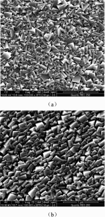
Surface morphology of nanochromium coatings deposited by magnetron sputtering for a 2 h and b 3 h
The X-ray diffraction patterns of chromium films deposited for 2 h are shown in Fig. 2, and their Cr(110) and Cr (211) peaks can be clearly seen.
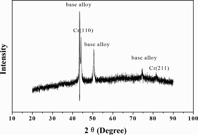
X-ray diffraction patterns of chromium films deposited for 2 h by magnetron sputtering
Electrochemical polarisation measurements
Figure 3 shows the potentiodynamic polarisation curves for bare steel and for chromium coatings with a pyramidal or columnar structure in 0·5M H2SO4. Both nanochromium coatings were in a passive state at the corrosion potential Ecorr, whereas the bare steel was in an active state at Ecorr. Ecorr and the corrosion current density Icorr for 316L stainless steel were − 293 mV SCE and 5·56 μA cm− 2 respectively. Ecorr and Icorr for the chromium coatings with a pyramidal structure were 27 mV SCE and 0·32 μA cm− 2 respectively, while for the chromium coatings with a columnar structure, they were − 43 mV SCE and 0·91 μA cm− 2 respectively. Both chromium coatings decreased the corrosion current density of the bare steel by about one order of magnitude. The chromium coating with a columnar structure showed inferior corrosion resistance due to its open structure.
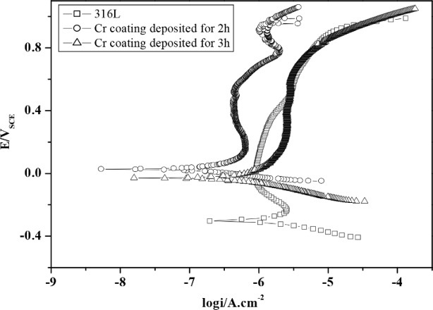
Potentiodynamic polarisation curves for 316L stainless steel and nanochromium coatings with different structures in 0·5M H2SO4 solution
Open circuit potential measurements
The OCP versus time curves for 316L stainless steel and the chromium coated 316L in 0·5M H2SO4 solution are shown in Fig. 4. For 316L, Eocp was maintained at about − 210 mV SCE in corrosive solution. Eocp for the chromium coated steel decreased to − 35 mV SCE for the initial 3 h immersion in corrosive solution, then increased gradually, and was maintained at ∼380 mV SCE with a small fluctuation during the total immersion time. Initially, the decrease in OCP was due to active dissolution in the corrosive solution. As a passive layer developed, the OCP increased and remained stable. The OCP was higher than that reported in the literature, 12 which was hypothesised to be related to the coating nanostructures.
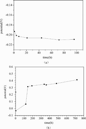
Open circuit potential–time curves for a 316L and b nanochromium coatings in 0·5M H2SO4 solution
Electrochemical impedance measurements
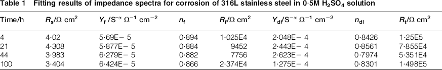
Typical Nyquist and Bode plots for the corrosion of 316L stainless steel in 0·5M H2SO4 after immersion for varying lengths of time are shown in Fig. 5. The Nyquist plots consist of two capacitive loops, which can be represented by the equivalent circuit shown in Fig. 6, where Rs is the electrolyte resistance, Rf and Cf are respectively the resistance and capacitance of the porous corrosion products formed on the alloy surface, and Rt and Cdl are the charge transfer resistance and double layer capacitance respectively. A constant phase element was used in the fitting procedures. The electrochemical impedance plots shown in Fig. 5 were fitted on the basis of the equivalent circuit, and the results are given in Table 1. The values of Rt tend to increase with exposure time, suggesting a decreased corrosion rate.
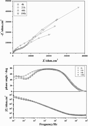
Nyquist and Bode plots for 316L after various exposure times at OCP in 0·5M H2SO4 solution; symbols: experimental data; line: fitted data
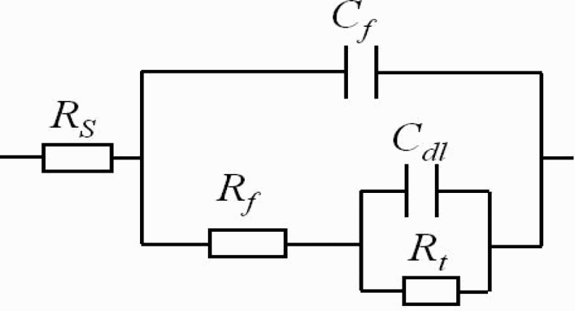
Equivalent circuit representing corrosion of 316L in 0·5M H2SO4 solution
Fitting results of impedance spectra for corrosion of 316L stainless steel in 0·5M H2SO4 solution
Typical Nyquist and Bode plots for the corrosion of nanochromium coated 316L stainless steel in 0·5M H2SO4 after immersion for varying lengths of time are shown in Fig. 7. After immersion for 3 h, the Nyquist plots consist of two capacitive loops, which were correlated with an incomplete chromium oxide film. With extended immersion time, the Nyquist plots consist of a small capacitive loop in the high frequency region and a nearly vertical line at low frequency. The Bode diagrams show a large frequency region of the maximum phase angle, with values greater than 85°, close to the 90° value corresponding to ideal capacitor behaviour. It has been reported that the EIS of anodised valve metals (such as Ti, Bi, Al, etc.) show similar characteristics in the initial period of oxide film formation in aqueous solution.13–15 However, previous studies have not reported similar results for chromium or other inactive films containing a developed passive film.
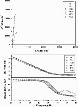
Nyquist and Bode plots for nanochromium coatings after various exposure times at OCP in 0.5M H2SO4 solution; symbols: experimental data; line: fitted data
It is well known that nucleation and growth are the key factors in passive film formation, and the nucleation of passive films generally occurs at defects, dislocations, grain boundaries and grain boundary junctions. 16 Compared to coarse grained structures, nanocrystalline materials are composed of a large fraction of surface defects that alter the nucleation mechanism of passive films from progressive to instantaneous. 9 Pan et al. employed the P-G transient technique to study the structure of passive films on nanoscale materials. 10 Their results showed that passive films are composed of multilayers, which are different from those grown on coarse grained materials.
The impedance diagrams for initial immersion (3 h) can be represented by the equivalent circuit shown in Fig. 6. The subsequent diagrams can be represented by the equivalent circuit shown in Fig. 8, where Cf represents the film capacitance, Rf is the resistance of the chromium film and Zd is the diffusion impedance of migrating chromium ions along the passive film. Figure 7 shows a close fit for the EIS of nanochromium coated steel in 0·5M H2SO4. Some electrochemical parameters are given in Table 2.
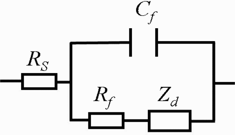
Equivalent circuit representing corrosion of nanochromium coatings in 0·5M H2SO4 solution
Fitting results of impedance spectra for corrosion of nanochromium coatings in 0·5M H2SO4 solution
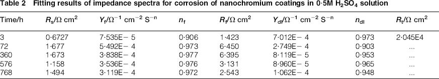
The values of Rf changed little with exposure time up to 768 h, indicating that the chromium coating retained high chemical stability in solution. The value of nf was related to surface roughness and the distribution of corrosion current on the electrode. When nf was close to 1, the film capacitance was close to that of an ideal capacitor. In this study, the values of nf were all close to 1, and varied little with exposure time between 72 and 768 h, indicating that a stable, passive film was formed. The SEM images of chromium coatings immersed in 0·5M H2SO4 solution for 768 h are shown in Fig. 9. It can be observed that the coatings remained undamaged, proving that the nanochromium coatings exhibit excellent corrosion resistance.
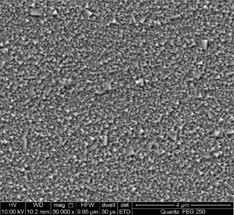
Surface morphology of nanochromium coatings immersed in 0·5M H2SO4 solution for 768 h
Conclusion
In this study, nanochromium coatings with either a pyramidal or a columnar structure were prepared by DC magnetron sputtering on 316L stainless steel. Both chromium coatings increased the corrosion potential of 316L by >300 mV SCE and decreased the corrosion current density by about one order of magnitude. Compared to chromium with a pyramidal structure, the corrosion current density of chromium with a columnar structure increased from 0·32 to 0·91 μA cm− 2 , indicating that its corrosion resistance decreased. The EIS confirmed that a distinct, passive film structure formed on the pyramidal nanochromium coating. The coatings exhibited high stability during 768 h of immersion in corrosive solution. The nanochromium coatings with a non-columnar structure formed by a magnetron sputtering technique act as an effective barrier to the inward penetration of corrosive species.
Acknowledgements
This project was supported by the National Natural Science Foundation of China (grant nos. 51301026 and 51172031), Natural Science Foundation of Hunan Province (granted no. 14JJ6019), Educational Commission of Hunan Province (grant no. 13B128) and Hunan International Incorporation Project of Sci & Tech (grant no. 2012WK2003).