
Abstract
An aluminium phosphate based high emissivity coating has been deposited on Ni based superalloy C-263 by dip coating method wherein the substrate was immersed in a chemical sol followed by curing of the green coating. Deposition of the coating by spraying the sol on the substrate surface has also been explored. The presence of carbon imparted high emissivity to the coating. Depending on the thickness of the coating, it exhibited an emissivity value of 0·6–0·9 in the wavelength range of 2.5–25 μm. The coating was found to offer good oxidation resistance to the substrate. Cyclic oxidation performance of uncoated and coated substrates has been evaluated at 800 and 1000°C for 100 h in air.
Introduction
High emissivity coatings have been used for effective heat transfer by radiation in the metallic thermal protection system (TPS) of space vehicles. Thermal protection system is typically fabricated from materials with high thermal stability and excellent thermal insulation properties. In addition, a high surface emissivity of TPS ensures controlled surface temperature and restricts undesirable inward heat transfer to protect the internal electronics. Ceramic coatings such as SiO2, ZrO2, SiC, Al2O3 and In–Sn oxide1–5 have been extensively studied for high emissivity applications in TPS and thermal control applications in aeronautical engines. These coatings have low density, excellent chemical and thermal stabilities. Emissivity of these coatings can reach values up to 0·8–0·9 depending on their composition, thickness, surface texture and surface roughness. Coatings containing compounds of zirconium, chromium and cerium along with phosphate and silicate binder systems can also be used for high emissivity applications on refractories.6,7 The composition of these coatings is so designed that they provide good coating strength, desired thermal expansion characteristics and adequate bond strength with the intended substrate. These coatings are also expected to have good oxidation resistance for improving their performance and longevity during use.
Deposition of thermal protection coatings can be carried out by various techniques such as arc evaporation, 8 microarc oxidation,9,10 plasma spray, 11 physical vapour deposition, 12 electron beam physical vapour deposition, 13 electrodeposition 14 and pack cementation. 15 Deposition of these coatings by dipping the substrate in a chemical solution or spraying the solution on substrate surface followed by curing at an elevated temperature has also been reported.16–18 Coating deposition by such a method is simple and allows deposition of a uniform coating over large areas. Coatings of metastable amorphous compound AlPO4 have been recently reported for high emissivity applications. Although this compound is known to have low oxygen diffusivity and does not undergo any phase transformation at elevated temperatures,19,20 its oxidation characteristics have not been reported in the literature. In our earlier paper, the deposition of an AlPO4 based high emissivity coating on Nimonic-75 alloy by sol–gel technique has been reported. 18 In the present paper, we report the deposition of the same coating on superalloy C-263 by dip and spray methods. Coating deposition on coupon level and on larger substrates has been carried out. Detailed microstructural characterisation of the coating and the evaluation of its high temperature oxidation performance in air have also been carried out.
Experimental
Substrate material
Ni based superalloy C-263 has been used as the substrate material. The nominal composition (wt-%) of this alloy is 19–21Cr, 19–21Co, 5–6Mo, 2·0–2·5Ti, 0·7Fe, 0·6B, 0·4Mn, 0·4Si, 0·2Cu and balance Ni. The above material was available in the form of 1·5 mm thick sheets from which samples of size 2 × 1 cm were cut. The surfaces of these samples were roughened by grit blasting using zircon sand. Subsequently, they were subjected to cleaning in trichloroethylene, hydrogen peroxide and acetone in that order. The cleaning was performed in an ultrasonic cleaner.
Chemical synthesis of aluminium phosphate sol
Aluminium phosphate sol was prepared using aluminium nitrate [Al(NO3)3.9H2O] and phosphorous pentoxide (P2O5) precursors. The details of this preparation have been reported in our earlier paper. 18 The synthesised sol was exposed to microwave radiation (in microwave baking oven) for 5 min and diluted in ethanol before deposition of coating on C-263 substrate.
Deposition of coating
For coating deposition by dip method, grit blasted substrates were immersed into the sol at a constant speed of 50 mm min− 1, allowed to remain there for 1 min and then withdrawn from the sol at the same constant speed. The dipping and withdrawal of the substrates were performed using a computer controlled programmable dip coater. After withdrawal, the excess liquid got drained off from the sample under gravity, and the solvent got evaporated leaving behind a layer of green coating. The green coated substrate was allowed to dry for ∼10 min at 120°C in an oven. Subsequently, they were cured at 800°C in a furnace in air to complete the coating process. For achieving higher thickness, the coating steps, i.e. from dipping in the sol to curing, were repeated multiple times. In such case, the first curing was carried out at a lower temperature of 500°C.
For coating deposition on larger substrates, spray technique was adopted in which the aluminium phosphate sol was sprayed on the substrate using a commercially available sprayer (DeVil Biss, UK, model no. 112GX) followed by its drying and curing in a similar manner as described above. For achieving higher coating thickness the process steps, i.e. from spraying to curing, were repeated multiple times.
Emissivity measurement
Emissivity of the coated surface was measured using a Bruker Vertex 80 V spectrophotometer equipped with an external emissivity measuring chamber. The measurement was performed in the wavelength range of 2·5–25 μm using the black body standard. The instrument measures the reflectivity from which emissivity was calculated using Kirchoff's law of heat transfer by radiation, i.e. emissivity = absorbivity = 1 − reflectivity.
Cyclic oxidation study
The uncoated and coated substrates were subjected to cyclic oxidation at 800 and 1000°C for 100 h in air using a box furnace. These temperatures were chosen keeping in mind the high temperature applications of the coating. Specimens were cleaned and weighed using a precision balance before oxidation. The specimens were taken out of the furnace after each cycle (which corresponds to 10 h of oxidation) and cooled to room temperature. After recording their weights, they were kept back into the furnace. This procedure was repeated until the completion of 100 h.
Microstructural characterisation
X-ray diffraction (XRD) with Cu Kα radiation was utilised for identification of phases in the coating in as coated condition and after oxidation. For further characterisation of the coated material, some ‘AlPO4 chemical sol’ was dried in an oven and calcined in air at a temperature in the range of 500–900°C. Raman spectroscopy was also performed on the dry powder that was obtained after calcinations. Carbon analysis of the coating material was performed using a LECO gas analyser (model no. CS444, LECO, USA). For observation of the coating material in a transmission electron microscope (TEM), coating in powder form was dispersed in ethanol, and a few drops of the suspension were dried on a carbon coated TEM grid. A FEI Tecnai 20T TEM was used for observation. The morphology of the coating surface before and after oxidation was characterised using a scanning electron microscope (SEM) of model LEO-440i. The SEM was also used for observing the cross-sectional microstructure of the coatings. The presence of elements such as C, Al, P and O in the coating was detected by X-ray photoelectron spectroscopy (XPS) measurements using a KRATOS AXIS HS spectrometer (using Al KR radiation). The C 1s (binding energy, 285 eV) peak was considered as the reference line for calibration of the energy scale.
Results and discussion
Morphology of coated surface
The present high emissivity coating based on amorphous AlPO4 was applied on C-263 substrate by dip coating technique followed by curing at high temperatures, as mentioned earlier. From our previous study, 18 it has been observed that coating deposition for multiple times is essential to improve the thickness uniformity of the coating over substrate surface. Therefore, mostly the coatings obtained by five times deposition (referred to as five-layer coating) have been considered in this study. The surface morphology of a five-layer coating is presented in Fig. 1a. The surface of the coating showed several cracks, although the coating was strongly bonded to the base substrate. This type of cracking has been reported in yttria stabilised zirconia ceramic coating deposited on metallic substrate by sol–gel dip coating. 21 It is believed that such cracking is caused by the uneven shrinkage resulting from quick densification of the coating material in the thicker regions as well as by the removal of alcoholic solvents during thermal treatment. Since the coating adheres to the substrate and cannot shrink in the direction parallel to the substrate surface, it leads to cracking in the coating layers. Despite the presence of cracks, the five-layer coating was found to be strongly bonded to the substrate. Observation of the coated layer in SEM at high magnifications revealed the presence of 2–5 nm sized AlPO4 grains (Fig. 1b). The above figure also revealed the presence of nanograins of hexagonal carbon. The presence of nanograins of C was confirmed by TEM analysis, as would be described later in the paper. The AlPO4 matrix was mostly amorphous because of the poor crystallinity of the ultrafine AlPO4 grains. As would be shown later, the amorphous nature of the coating was also evident from the XRD pattern.
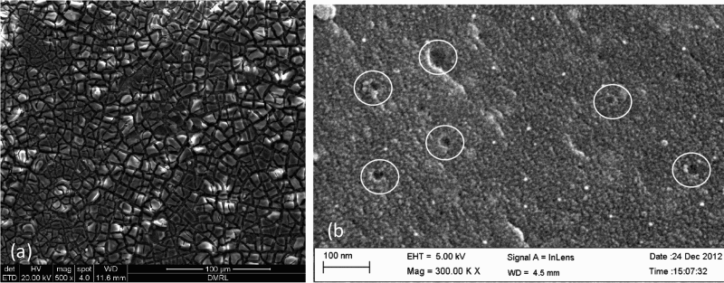
a images (SEM) of five-layered coated and cured substrates, b microstructure of coating at very high magnification ( × 300 000) (hexagonal graphitised carbons distributed in AlPO4 matrix are encircled)
Composition of coating material
The calcinations of the sol, as mentioned earlier, yielded a black coloured powder, which was a composite of graphitised carbon (5–6 wt-%) distributed in the matrix of AlPO4. Graphitized carbon imparted the black colour to the above powder. The presence of carbon in the composite powder in case of all the calcined samples was confirmed by Raman spectroscopic characterization. Figure 2a and b shows the Raman spectra of corresponding to the powders calcined at 700 and 900°C respectively. The peaks at 1345 and 1600 cm− 1 can be attributed to the presence of graphitized carbon, as reported by Wang et al. 22 and Tuinstra et al. 23 The presence of Al, P, O and C in the AlPO4–C composite powder was also detected by XPS spectroscopy. Figure 3, which shows the XPS spectra of the composite powder, indicates the presence of Al 2p, P 2p, C 1s and O 1s. This result confirms that the coating material was indeed a composite consisting of AlPO4 and carbon. The concentration of carbon in the composite powder corresponding to the calcinations temperature of 900°C was determined to be ∼5 wt-%. The source of carbon in the coating can be attributed to the alcohol used in the sol. No carbonaceous material other than the alcoholic solvent was used in the synthesis of the coating material. In AlPO4–C composite coating material, the matrix retained its amorphous nature up to very high temperature. The carbon present in the composite was protected from oxidation at high temperatures due to extremely low oxygen diffusivity in the amorphous AlPO4 matrix.19,20 A high resolution TEM image of the above composite powder, as shown in Fig. 4, revealed the presence of nanocarbon with hexagonal symmetry.
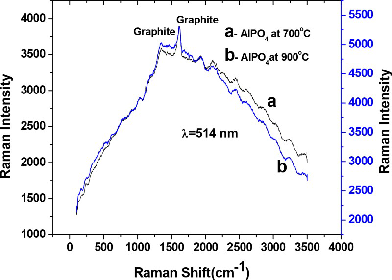
Raman spectra of AlPO4–5 Ni composite samples calcined at a 973 K and b 1173 K
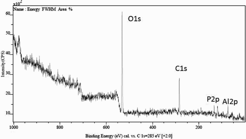
a X-ray photoelectron spectroscopy spectra of AlPO4–C composite powder showing peaks for Al 2p, P 2p, C 1s and O 1s at 74·8, 134, 285 and 532 eV respectively
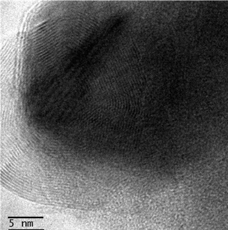
Image (HRTEM) showing presence of graphitised carbon in AlPO4 matrix of AlPO4–C composite powder (d = 3·30 Å) (002 plane of carbon)
Measurements of emissivity
Absorptivity α is the material property that describes the capability of a material to absorb electromagnetic radiation and has a value between 0 and 1. According to Kirchhoff's second law, 24 α = ε, where ε is emissivity of the material. The energy conservation law, i.e. ε+τ+ρ = 1, correlates three different optical properties of a material, namely emissivity ε and coefficients of transmission τ and reflection ρ. Since τ ≈ 0 for an opaque coating, its emissivity ε = 1 − ρ. The instrument used in the present study measured the reflectivity of the coated surface at variable wavelengths. The results of the reflectivity measurements in the wavelength range of 2.5–25 μm are shown in Fig. 5. As evident, the distribution of radiative energy over the wave length range of 2.5–25 μm remained almost constant with the variation of coating thickness. Emissivity values of five- and 10-layer coatings, measured over wavelengths of 1–7 μm, were in the range of 0·7–0·9. However, the values remained at ∼0·9 over the wavelength range of 7–25 μm (Fig. 5). Further, the emissivity of the three-layer coating was also found to be considerably higher (0·89). The average emissivity values for one-, three-, five- and 10-layer coatings were calculated by taking the average of the emissivity values over the entire wavelength range of 2.5–25 μm. The variation of coating thickness and its emissivity with the number of coating layers is shown in Fig. 6. This figure shows that the value of emissivity increases with increasing the number of coating layers up to five layers beyond which it remains constant at 0·9 with further increase in number of layers. Similar results in terms of variation of emissivity with coating thickness for other coating compositions have also been reported.25–27 This phenomenon of constant emissivity above a critical coating thickness can be explained as follows. When the coating thickness is low, light can penetrate through the coating and reach the substrate. Therefore, the coating emissivity gets influenced by that of the substrate. However, beyond a critical thickness, the contribution of the substrate to the overall emissivity becomes minimal. Therefore, the measured emissivity of the coating remains constant beyond a certain thickness.
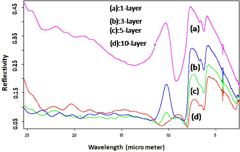
Variation of reflectivity (1 − emissivity) with wave length of one-, three-, five- and 10-layer coating
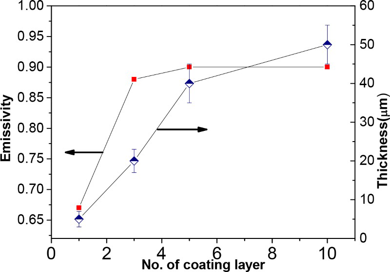
Variation of coating thickness and emissivity with number of coating layer
Feasibility of coating deposition on larger substrates by spray method
Feasibility of applying the high emissivity coating by spray technique was tried by spraying the AlPO4 chemical sol on Nimonic-75 and C-263 sheets of larger sizes (300 × 200 mm) using a commercially available spray gun as stated earlier. Subsequently, the required drying and curing were carried out. It was observed that the coating could be successfully applied on these larger substrates by spray deposition technique. Figure 7 shows the photograph of the coated and C-263 sheet.
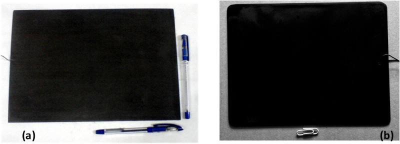
Digital photographs of coated and cured a Nimonic-75 and b C-263 substrates of size ∼30 × 20 cm obtained by spray coating technique
Oxidation performance of uncoated and coated substrate
High temperature oxidation resistance of the coating is important for its survival during the actual application. The applied thermal protection coating must provide good oxidation resistance for improving the performance and longevity of the space vehicle. In the present work, the oxygen diffusivity in the coated material, i.e. the amorphous AlPO4, is extremely low, and the coating was found to impart good oxidation resistance. The oxidation resistance of the coated material was checked by heating a coated and bare substrate at 800°C for 1 h in air. It is to be noted that this heat treatment schedule (800°C for 1 h) is different from the heat treatment schedule for cyclic oxidation studies (800 and 1000°C for 100 h).
The XRD diffractograms of uncoated and coated substrates after oxidation exposure are shown in Fig. 8. Uncoated substrate after oxidation showed strong peaks of Cr2O3 and MoO3. The intensity of these lines is much lower in case of coated substrate. In an earlier paper, 18 we reported the results of a similar study using Nimonic-75 substrate. In that study, it was observed that the metal oxide peaks were completely absent after oxidation (at 800°C) of coated substrate, although the uncoated substrate showed strong peaks of NiO. 18 These results indicate that amorphous AlPO4 coating imparts considerable oxidation resistance to the present C-263 substrate at 800°C. To evaluate the oxidation resistance at higher temperatures, cyclic oxidation was performed on uncoated and coated C-263 for 100 h at both 800 and 1000°C, as mentioned earlier. Samples with five-layer coating were considered for the cyclic oxidation study. Figure 9 shows the weight change data obtained during oxidation. The coated substrate showed very low weight change throughout the entire oxidation duration of 100 h, signifying minimum oxidation of the base substrate. In contrast, the uncoated substrate exhibited substantial weight changes during oxidation. Moreover, the oxide layer formed on the uncoated substrate underwent spallation multiple times, which was reflected in terms of large fluctuations in the weight change curves for both the temperatures (800 and 1000°C). Spallation in any step of cyclic oxidation could be characterized by sudden weight loss, which eventually resulted due to the ‘oxidation–weight gain’ in the previous steps. From the figure, it is observed that, for the bare substrates, spallation occurred multiple times (third, fifth and ninth cycle in Fig. 9a; second cycle in Fig. 9b) during 100 h of cyclic thermal exposure. Gradual weight losses in the third, fourth, fifth and sixth cycle in Fig. 9b would indicate occurrence of ‘oxidation–weight gain’ and ‘spallation–weight loss’ in a single step.
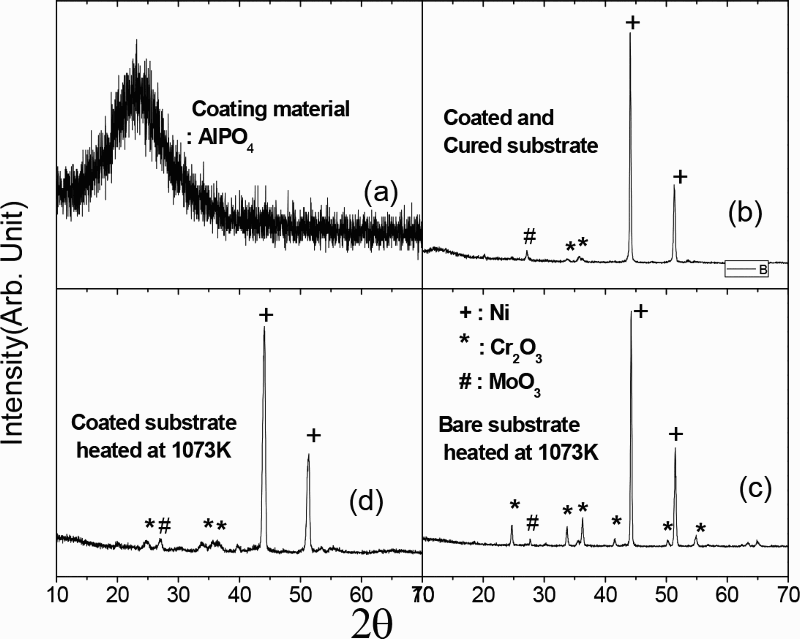
X-ray diffraction patterns of a amorphous AlPO4, b coated substrates as obtained after curing, c uncoated substrate heated at 1073 K and d coated substrate heated at 1073 K for 1 h in air
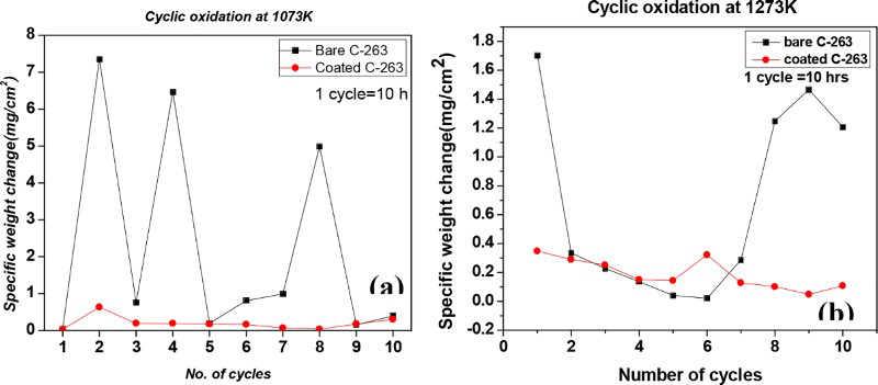
Cyclic oxidation test of uncoated and coated substrates at a 1073 K and b at 1273 K
Cross-sectional microstructure and surface morphology
Figure 10 shows the SEM images of the cross-section of uncoated and coated substrate after oxidation at 1000°C. The substrate/coating interface appears to be free from crack and delamination (Fig. 10a). However, after oxidation, an increase in coating thickness was apparent because of the incorporation of the oxidised product in AlPO4–C coating matrix. Comparison of the coating thickness before and after cyclic oxidation revealed an increase in coating thickness by 5–10 μm after cyclic oxidation for 100 h at 1000°C. In spite of that, the composite coating was able to accommodate the generated stress, and no crack in the coating layer was observed in the cross-sectional view.
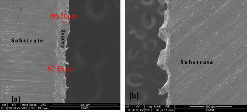
Images (SEM) of oxidised surface–cross-section of a coated and b uncoated C-263 substrate obtained after cyclic oxidation test at 1273 K
It should be mentioned that the oxidised surface of the uncoated substrate was examined after multiple spallation of the oxide layer during thermal cycling. From the Fig. 10b, it is observed that the uncoated alloy surface developed thick oxide layer during oxidation at 1000°C, which spalled subsequently. The rapid growth of the oxide layer and its spallation resulted in an extremely uneven oxidised surface, which is also apparent from the cross-sectional microstructure (Fig. 10b).
Figure 11a presents the oxidised surface of the uncoated substrate obtained after multiple spallation of the oxide layers. Detailed SEM analyses of the oxides revealed the growth of an NiO layer on the top of a Cr2O3 layer in case of the uncoated substrate cycled at 1000°C for 100 h, signifying the diffusion of Ni towards the surface (outward diffusion) in preference to Cr. Prevalence of NiO in the top oxidised layer formed on uncoated alloy was also confirmed by SEM-EDAX analysis (Fig. 11a, inset) and by XRD analysis.
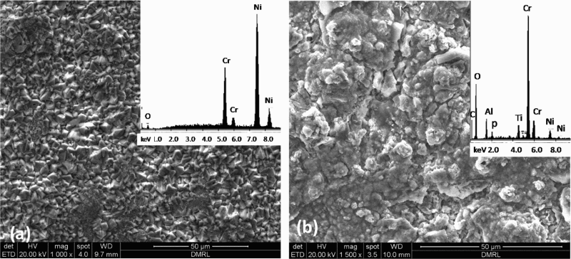
Image (SEM) of a uncoated and b coated C-263 surface oxidised at 1273 K; insets show SEM-EDX spectra of oxidised surface
Figure 11b shows the surface morphology of the coated substrate after oxidation at 1000°C for 100 h. No delamination of the coating was observed on the oxidised surface. In spite of oxidation of the substrate below the coating, the coating was found to be adherent to the substrate. Detailed SEM-EDX analysis indicated the diffusion of Cr towards the surface (outward diffusion) in preference to Ni leading to enrichment of Cr2O3 on the top oxide layer (Fig. 11b, inset). X-ray diffraction analysis of the surface also showed stronger peaks of Cr2O3 as compared to those of NiO, which was in accordance with the SEM-EDAX results and in sharp contrast with the NiO enrichment in case of uncoated substrate.
Conclusion
An aluminium phosphate based high emissivity coating was deposited on C-263 superalloy substrate by dip coating and spray coating techniques. The presence of nanocarbon in a nearly amorphous AlPO4 matrix was detected by Raman spectroscopy, XPS spectroscopy and TEM. Carbon nanoparticles were protected from oxidation in the amorphous AlPO4 matrix at elevated temperatures and were responsible for imparting high emissivity to the matrix. The coated alloy exhibited emissivity values in the range of 0·67–0·90 depending on the thickness of the coating. Emissivity increased with the increase in coating thickness up to a certain thickness beyond which the value remained constant at 0·9. Apart from exhibiting high emissivity, the coating also provided good oxidation resistance to the substrate at 800 and 1000°C for over 100 h of thermal cycling exposure. The oxide phases that formed during oxidation of uncoated and coated substrates were NiO and Cr2O3. The coating did not develop any crack under the stresses caused by the oxide growth during oxidation exposure.
Acknowledgements
The authors thankfully acknowledge the financial support from the Defence Research Development Organization, Ministry of Defence, Government of India, New Delhi, for carrying out the present work. Authors are thankful to the Director, DMRL, for giving permission for carrying out the research work. The authors would like to thank Dr S. Mahajan, Project Advisor; Dr S. S. Prasad, Project Leader; Dr S. V. Kamat, Division Head; and Dr T. Raghu for their constant encouragement and helpful discussion. The authors also wish to thank Dr P. Ghosal and Dr A. K. Singh, scientist, DMRL, for his help in SEM and XRD respectively.