
Abstract
The effect of single and two-stage Si modified aluminide coatings on thermal fatigue behaviour of nickel based superalloy Inconel 713LC was examined. Specimens were loaded under test condition of heating to 1100°C followed by cooling to25°C. The experimental results showed that the coatings increased thermal fatigue resistance in both crack initiation and propagation stages. The comparison of the crack growth rates indicated that both coatings imparted resistance to the crack lengthening. However, the effect of single stage coating on the fatigue resistance was superior compared with that of two-stage coating. Through scanning electron microscopy observation, it was found that the width of γ′ denuded zone was the main reason in the control of crack growth in all specimens.
Introduction
Cast polycrystalline nickel based Inconel 713LC is used in the manufacturing of power plant as well as aircraft gas turbine blades. These blades are subjected to repeated mechanical as well as thermal loadings in corrosive condition at high temperatures 1 . Nickel based superalloys possess good mechanical properties at high temperatures, whereas their high temperature oxidation resistance is relatively acceptable at working temperatures. However, in order to increase the service life of turbine engine blades, efforts are focused on the improvement of their high temperature corrosion resistance as well as fatigue strength. It should be noted that application of coatings should not deteriorate the mechanical properties of the parts. Diffusion coating is one of the most used protective coatings that change the surface chemical composition in order to improve the high temperature oxidation and hot corrosion resistance of blades.2,3
Aluminide coating has been applied to gas turbine vane and blade surfaces for a long time. Despite development of new coatings such as MCrAlYs, majority of the coatings applied to the first-stage blade airfoils are still aluminide coatings. Among the various coating techniques, the pack cementation process is an effective and inexpensive method. Thus, pack aluminising with or without other elements is widely applied to nickel based superalloys in order to improve their high temperature oxidation and hot corrosion resistance.4-6
During Si modified aluminide diffusion coating, a relatively thick layer of the surface is saturated with Al and Si. Usually aluminising is performed in high activity mode, where the growth of the coating layers is controlled by inward aluminium diffusion. These coatings are mainly produced by pack cementation method with either single or two-stage method. In the single stage method, coating is produced at the temperature range of 1000–1050°C, whereas in the two-stage method, coating layer is produced at temperatures of 700–950°C, which follows by heat treatment at temperatures as high as 1000–1050°C. During single stage coating, a two-layer coating forms on the substrate from the beginning, including outer and interdiffusion layer. NiAl is the major phase in the outer surface layer. The interdiffusion layer consists of columnar phase formed mainly due to the inward diffusion of aluminium and outward diffusion of nickel. Two-stage coating produces a single coating layer of Ni2Al3 with some Si at the first stage of the coating. After applying heat treatment at the second stage, a layer of NiAl forms at the Ni2Al3/substrate interface. Formation of this layer is mainly due to the interaction of the original coating layer of Ni2Al3 with nickel from the substrate.6-9
Thermal fatigue is a potential mode of failure in parts that are exposed to temperature fluctuation. Thermal cycle fatigue, caused by cyclic temperature changes during operations, is an important life limiting parameter for many operating parts such as turbine vanes and blades. When metals expand and contract during the sudden temperature change, they inevitably undergo a transient strain and stress. Repetition of this thermal shock may cause the generation of the plastic deformation in some local area where thermal stress is high enough. Thermal fatigue behaviour of the parts is a function of their chemical composition, microstructure and surface condition.10-12 In this article, the effect of Si modified aluminide coating on the thermal fatigue behaviour of Inconel 713LC is studied.
Materials and experimental procedures
Nickel based superalloy of Inconel 713LC was used as the substrate in the as cast condition. Table 1 shows the chemical composition of the alloy. Thermal fatigue specimens were cut from the cast bar with the dimensions of 14 × 10 × 3 mm, and then, a V type notch was formed on the specimen surface (Fig. 1). Notch direction was vertical to the dendrites' direction. The samples were then polished and dried. Before the fatigue test, the surface around the notch was examined by an optical microscope for the possible microcracks around the notch.
Average chemical composition of substrate used in this study/wt-%

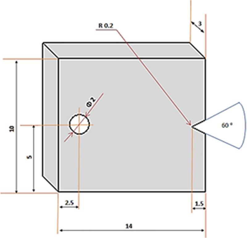
Dimensions of specimen used in this study/mm
Thermal fatigue cycles were designed such that specimens first were heated to temperature as high as 1100°C and held at that temperature for ∼10 min. Samples then were cooled to room temperature by inserting them into a tank containing 25°C water for 30 s. The cycles were repeated for certain numbers. Then, the surface of the samples was surveyed for the number of cracks and their length using the optical microscope. The number of cycles at which the crack length was ∼200 μm was recorded as the cycles for crack beginning.
Some of the samples were coated before the fatigue test. Before the coating, specimens were smoothened with 800 grit paper and cleaned by immersing in 5M hydrochloric acid for 5 min followed by ultrasonically cleaning in an acetone bath for 30 min.
For production of single stage coating, the specimen was packed in a mixed powder comprised of 83·5 wt-%Al2O3, 7·5 wt-%Si, 5 wt-%Al and 4 wt-%NH4Cl (as an activator) in an alumina crucible. The pack was heated to 1055°C and hold for 3 h, while argon was flowing over the pack. In the two-stage coating, the specimen was packed in mixed powder of 72 wt-%Al2O3, 17·5 wt-%Si, 2·5 wt-%Al and 8 wt-%NH4Cl. The pack was heated to 900°C and kept at that temperature for 5 h and then heat treated at 1055°C for 3 h under argon atmosphere; the typical microstructure of the two-stage coating after heat treatment is shown in Fig. 2. The coating included three distinct layers along its 110 ± 10 μm thickness. X-ray diffraction pattern revealed the fact that coating was mainly NiAl phase (Fig. 3). However, energy dispersive spectroscopy (EDS) analysis indicated that small precipitates containing chromium and silicon were present in the coating outer layer. In fact, some peaks from X-ray diffraction pattern were not identified, which could be related to the mentioned precipitates. The intermediate layer was NiAl without any precipitation, while the inner layer was consistent with an interdiffusion zone.
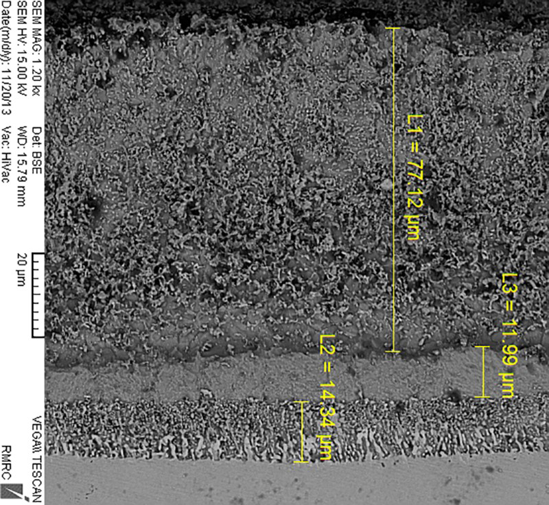
Scanning electron microscopy coating microstructre before application of thermal cycling
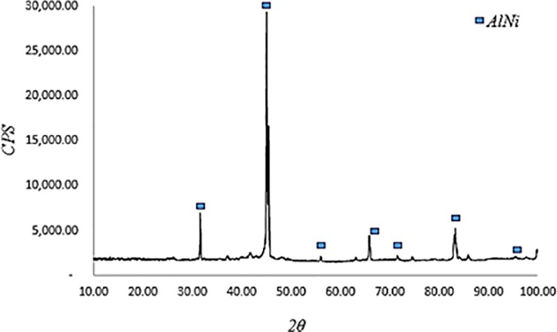
X-ray pattern of as coated sample in two-stage coating process
The microstructure of the coating obtained in the single stage coating was almost similar to that of the two-stage coating process. However, X-ray diffraction pattern of the coated sample showed that the coating was mainly Ni0·9Al1·1, as shown in Fig. 4.
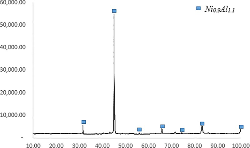
X-ray diffraction pattern of as coated sample in single stage coating process
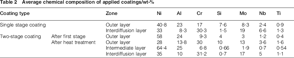
The coating layers' compositions were analysed using EDS, and results are shown in Table 2. The microhardness test was performed with a Vickers indenter with 0·49 N force.
Average chemical composition of applied coatings/wt-%
Results and discussion
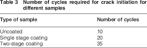
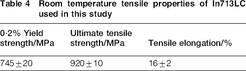
The number of thermal cycles needed for critical crack initiation in coated and uncoated specimen is listed in Table 3. The results show that both coatings increased the incubation period, i.e. life before crack initiation, compared with the uncoated sample. Incubation period depends on the microstructure and mechanical properties. As cast IN 713LC have relatively high yield strength, medium ultimate tensile strength and low ductility, as shown in Table 4, due to the large amount of γ′ precipitates. MC carbides, mainly Nb carbide, were uniformly distributed within the substrate. These MC carbides act as the sources of crack nucleation sites as well as the crack propagation paths, as other researchers have demonstrated.10–13 Temperature fluctuation during thermal fatigue causes expansion and contraction of the sample. Owing to the difference in expansion coefficient of MC carbides with that of the matrix, high amount of stresses are formed at the carbide/matrix boundaries. In case the local stress intensity exceeds the yield point of the substrate, a plastic deformation occurs as a crack. Therefore, cracks nucleate at the MC carbides and the matrix boundary. Further thermal cycles lead the crack to propagate. Propagation promoted by the notched edge, and as a result, cracks are propagated along notch edge direction.
Number of cycles required for crack initiation for different samples
Room temperature tensile properties of In713LC used in this study
Dependences of thermal fatigue crack length to thermal cycle are shown in Fig. 5. Crack length values are representatives of maximum crack length found in the specimens. It can be seen that both coatings imparted high resistance to the crack growth compared with the uncoated sample. However, the effect of the single stage coating is superior to that of the two-stage coating, as the crack length at high number of cycles shows.
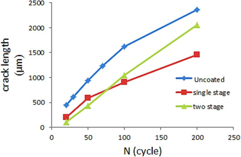
Thermal fatigue crack propagation kinetics of different samples
Usually, the growth direction of thermal fatigue cracks is nearly 45° to the direction of dendrite in microstructure. This is assigned to the face centred cubic structure of the nickel based superalloy with the slip system of ⟨110⟩{111}. The growth direction of primary dendrites is considered as ⟨110⟩. If the already formed notch is considered as a predetermined crack, ⟨110⟩ orientation is subjected to the maximum shearing stress, and therefore, initiation and propagation of crack along this orientation would be promoted, as reported by Xia et al. 14 In a cast polycrystalline structure, interdendritic regions are vulnerable places to thermal fatigue and, hence, are preferred as the crack sources and propagation area.
The Al–Si diffusion coating changes the surface properties and integrity of the substrate. It is expected that the crack initiation and propagation in coated specimen be different from the uncoated one. During the initiation stage in the uncoated specimen, many small cracks are nucleated at the surface, especially in the notch region where small pores were induced by high temperature oxidation, as reported by other researchers.15,16 Therefore, with continuing thermal cycle and stress concentration on the notch region, these small cracks act as preferential places for crack initiation. This was not observed in the coated specimens.
The improvement in the incubation time for the aluminide coating samples could be attributed to the increase in the surface characteristics. Aluminide coating not only imparted a protective layer to the oxidation process but also increased the surface hardness. The surface hardness was measured as 950 and 640 HV in the outer layer of the single and two-stage coatings respectively, whereas that of the substrate was ∼390 HV. Increase in the surface hardness leads to restraining the crack nucleation.
Another important mechanism in crack initiation and its propagation that should be noted is the formation of γ′ phase drained regions close to the crack surface. During the thermal fatigue test, the material underwent a microstructural change close to the notch. Observation by SEM confirmed that, in the uncoated specimens, some of the γ′ phase close to the surface area started to coalesce and disappear (region A in Fig. 6), whereas the microstructure of the parts far from the cracks remained unchanged and cubic (region B in Fig. 6).
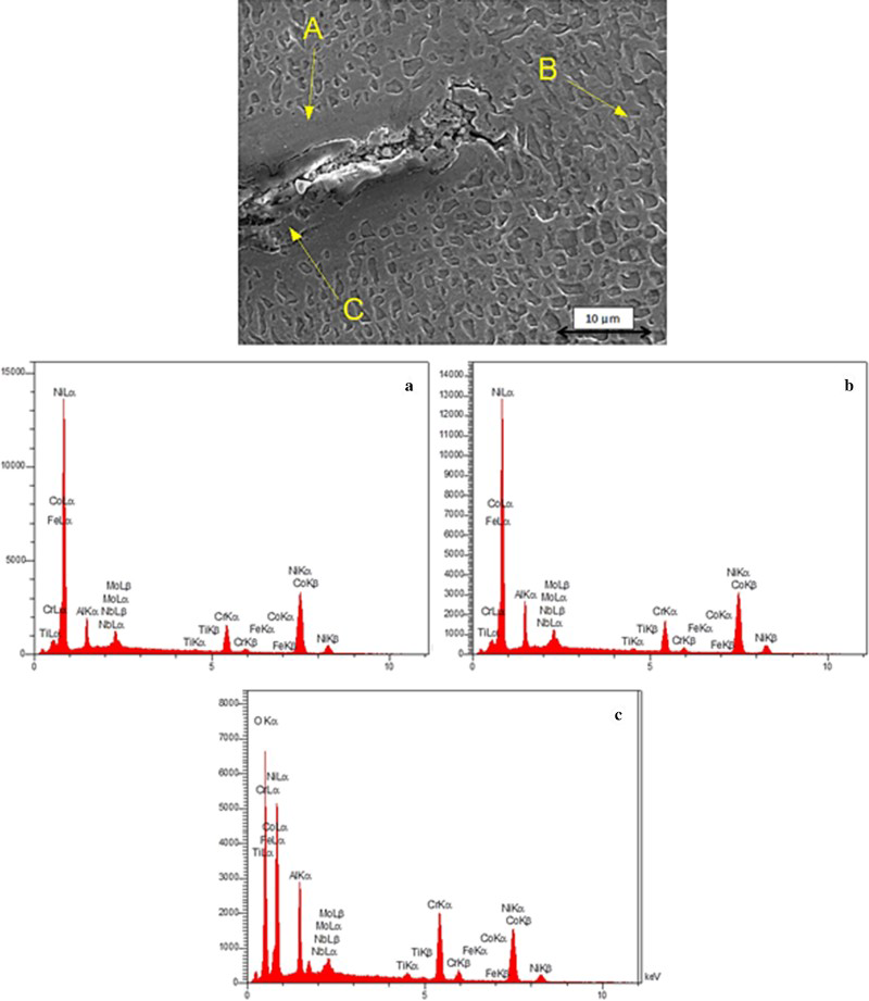
Crack initiation of single stage coated specimen after 50 cycles at 1100°C and EDS analyses of indicated points: a γ′ denuded zone;b γ′ + γ zone;c crack
X-ray map analysis pointed out that Al in the γ′ denuded zone near the cracks was lower than the substrate, and the oxide layer near the main crack appeared to possess more aluminium than the bulk.
The EDS analysis also showed that the composition of Al and Cr, in the γ′ denuded zone, was lower than those in the bulk substrates. Owing to the high temperature exposure, these elements are most probably reacted with the oxygen in the atmosphere to form stable oxides of Al2O3 and Cr2O3 as shown in region C in Fig. 6.
Formation of the γ′ drained zone was mainly due to the combined interaction of thermal stress and the elemental diffusion of aluminium that is the main forming element of γ′ phase. Aluminium is diffusing out of the alloy microstructure to react with oxygen from the atmosphere to form islands of aluminium oxide, which thermodynamically is stable at the experimental condition. Thus, in the uncoated specimens, all surface areas are susceptible for crack initiation and propagation.
The oxide layer formed after 20 thermal cycles on the crack surface was studied. The microstructure was comprised of an outer layer of NiO and an inner layer consisting of mixtures of Al2O3 and Cr2O3. Some internal oxides of alumina and chromia were also observed beneath the surface (Fig. 7).
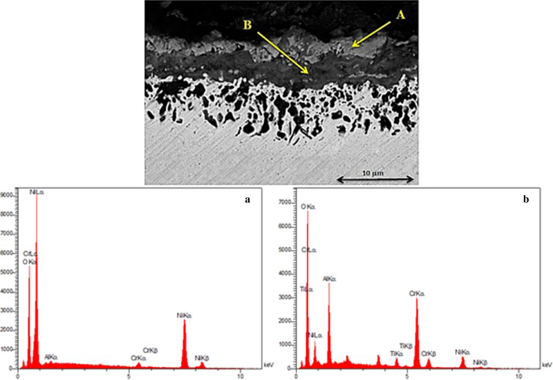
Energy dispersive spectroscopy analysis of oxide layer formed on top of uncoated specimen after 20 cycles at 1100°C: a NiO layer; b Al2O3 and Cr2O3 layer
The γ′ phase depleted regions are not observed in the coated specimens. During exposure of the specimen to oxygen, the amount of aluminium that is needed for the formation of stable alumina is provided by the coating layer instead of diffusing out from the substrate. Therefore, there is no aluminium depletion at the notch tip, at least at the small number of fatigue cycles.
Silicon, as an oxygen getter element, reduces the amount of aluminium necessary for the formation of alumina. Therefore, it is concluded that applying the silicon modified aluminide coating gave more resistance to crack initiation and propagation by controlling the γ′ denuded zone. Analysis by EDS of some of the particles in Fig. 7 showed that aluminium, nickel, chromium, molybdenum and silicon were present in the amounts of 13·6, 33, 36, 3·4 and 12·2 wt-% respectively.
The aluminium content in the uncoated specimen is not enough to form a continuous passive alumina layer. By increasing the thermal fatigue cycles, more aluminium diffused to the crack surface, and hence, the width of the γ′ denuded zone was increased.
However, after large number of thermal fatigue cycles, γ′ drained zone was observed in all coated and uncoated samples, but the width of this zone that plays important role in controlling the crack growth varied with surface composition and integrity conditions. The width of γ′ drained zone was smaller in silicon modified aluminide coatings compared with the uncoated samples. It should be noted that, even in the case of coated samples, the width of depleted zone was increased with increase in fatigue cycles, which is the indication of a combined creep and environment damage occurring during thermal cycles.
However, the thermal stress or localised plastic deformation increases the diffusion flux in the region close to the crack tip. 17 By depletion of γ′ forming elements, the amount of the γ′ phase dramatically lowered, and thus, the strengthening effect of γ′ decreased in the γ′ denuded zone. Thus, crack propagation was enhanced and facilitated in this area.
Difference in thermal expansion coefficient of the oxide layer and matrix alloy results in oxide spallation and further exposure of the bare surface to oxygen for oxidation at the crack surface during the thermal cycle fatigue. However, for the coated specimen, as the oxide layer is continuous, and oxide molar volume is a little higher than that of the substrate, a slight compressive stress arises, which prevents oxide from spallation.
Conclusion
Exposure of the uncoated sample to oxygen at high temperature resulted in diffusing out of aluminium to form discrete islands of alumina. This caused formation of γ′ denuded zone near the surface of the uncoated specimen. Thermal fatigue introduced stress, which was locally intensified at the crack tip. Owing to the interaction of thermal stress and elemental diffusion, the morphologies of γ′ close to the primary cracks changed in such a way that they coalescence with each other. Silicon modified aluminide diffusion coating supplied aluminium to the surface, enough for the formation of Al2O3. Therefore, there was no aluminium diffusion out of the substrate, and hence, the γ′ depleted zone was not observed at least at the small number of thermal cycles. Si modified aluminide diffusion coating increased surface hardness and also introduced compression stress by alumina formation. These two parameters helped in decreasing the crack growth rate.
Footnotes
Acknowledgement
The authors would like to acknowledge the financial support provided by the Materials and Energy Research Center.