
Abstract
This study investigated the photocatalytic activity of an Fe containing TiO2 film produced in the FePO4 electrolyte via the plasma electrolytic oxidation (PEO) method. For this purpose, the PEO process was carried out on titanium substrate under ac condition in two different alkaline electrolytes containing K3PO4 and FePO4 respectively. The structure, chemical composition and constituent phases of the PEO treated samples were analysed via SEM, X-ray photoelectron spectroscopy and X-ray diffraction. The optical properties of the samples were also examined by an ultraviolet–visible spectrophotometer. In terms of the photocatalytic activity judging from the decomposition of methylene blue under visible light illumination, the sample formed in the FePO4 electrolyte was better than that in the K3PO4 electrolyte due to the incorporation of an Fe compound that has a narrow band gap.
Introduction
In recent years, photocatalysis has been known to be desirable for eliminating organic contaminants from water and air via photochemical reactions accompanying photogenerated holes and electrons. 1 As one of the good candidates, pure TiO2 is selected due to its excellent properties such as good chemical stability, high photocatalytic activity, etc.2–4 For the pure TiO2 with a fairly large band gap energy of ∼3.2 eV, many works have paid particular attention to reduce the band gap energy of TiO2 since only ultraviolet (UV) light could be absorbed in the thin film devices with TiO2. 5 Thus, several techniques, such as sol–gel, chemical vapour deposition, physical vapour deposition and hydrothermal process, have been reported to couple TiO2 with transition metal oxides having narrow band gaps in order to extend the optical adsorption edge into a visible light region. 6 For instance, the heterogeneous composites of the TiO2 film together with WO3 and CuO compounds gave rise to the increase in the photocatalytic activity.7,8
Plasma electrolytic oxidation (PEO) is an attractive electrochemical method that can fabricate a porous TiO2 film incorporated with secondary metal oxides by controlling metal salts in the electrolyte as the plasma discharges activated the plasma enhanced electrochemical reactions.9,10 As such, several approaches have been reported to improve the photocatalytic activity of the TiO2 film utilizing the PEO method; the introduction of V2O5, WO3 and ZrO2 into TiO2 films and how they existed and acted on photocatalytic activity were discussed.11–13
On the basis of the band gap positions for various traditional semiconductors, Fe2O3 has a relatively low band gap (∼2.2 eV). 14 Regarding this characteristic, the fabrication of Fe incorporated titanium oxide for enhancing photocatalytic properties has received much attention in recent years.15–17 Wu et al. 15 demonstrated that the Fe3+ ions could be successfully incorporated into the titanium oxide in the H2SO4 acidic solution containing Fe2(SO4)3 electrolyte. Moreover, Soejima et al. 16 manipulated the concentration of α-Fe2O3 nanoparticles in the acidic solution to fabricate Fe doped TiO2 films. In other words, most of the studies have used acidic electrolytes, and little attention has been paid to the introduction of Fe2O3 via the PEO process in ecofriendly alkaline solutions. In this regard, we successfully fabricated the TiO2 film containing Fe2O3 on titanium subjected to the PEO process using a KOH electrolyte with FePO4. The main aim of this study is, first, to observe the surface structure and constituent phase of the TiO2 film treated in the alkaline electrolyte with FePO4 in comparison to the results with K3PO4 and, second, to examine the optical properties and photocatalytic activity under visible light illumination.
Experimental
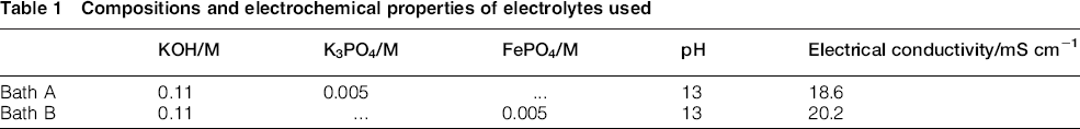
Before the PEO process, commercially pure titanium (grade II, Hyundai Titanium) samples with a size of 20 × 30 × 2 mm were ground with no. 100–1000 abrasive papers and ultrasonically cleaned in pure acetone. The PEO process was conducted utilizing a 6.5 kW ac power supply (ACP Korea, ACP-1010) in conjunction with stirring and cooling systems. The electrolytic cell consisting of a glass vessel with a sample holder and stainless steel mesh of dimensions 15 × 25 cm was used as a cathode. The chemical compositions and electrochemical properties of the electrolytes used in this study are listed in Table 1. The electrolytes with K3PO4 and FePO4 are denoted as ‘bath A’ and ‘bath B’ respectively. The temperature of present electrolytes was maintained at 293 K so as to stabilise the electrochemical condition during the PEO process. Plasma electrolytic oxidation coatings were prepared for 600 s at a current density of 100 mA cm− 2. The thickness of both films was controlled to be ∼4 μm so that other effects on the photocatalytic activity could be avoided except for the composition effect.
Compositions and electrochemical properties of electrolytes used
The surface morphologies and chemical compositions of the TiO2 film PEO treated in baths A and B were examined using a field emission scanning electron microscope (SEM, HITACHI S-4800) equipped with energy dispersive X-ray spectroscopy (AMETEK Genesis APEX2). X-ray diffraction (RIGAKU D/MAX-2500/PC), operating at a voltage of 40 kV with a step size of 0.05° and a scan range from 20 to 60°, was utilised to analyse the constituent phases of each film. The chemical compounds present in the two different films were detected by X-ray photoelectron spectroscopy (XPS, VG SCIENTA R300) using a monochromatic Al Kα (1486.6 eV) X-ray source with a beam size of 400 μm diameter and a 90° take-off angle. The ultraviolet–visible (UV–vis) diffuse reflectance spectra were obtained using a UV–vis spectrophotometer (JASCO V-650) with a scan rate of 200 nm min− 1 in a range of 200–600 nm.
The photocatalytic activity of the PEO treated titanium samples was evaluated through the degradation of methylene blue.5,18 A 500 W Xe lamp was used as a light source, with the distance of 15 cm to the photoanode surface, irradiated perpendicularly to the sample that was entirely immersed into 30 mL aqueous methylene blue solution (2 × 10− 5M). Before the irradiation, the methylene blue solution was magnetically stirred in the dark for 30 min to establish the adsorption/desorption equilibrium among photocatalyst, sample and water. 19 At a given time, the absorbance of degraded methylene blue solution taken in 1.5 mL cuvette every 30 min was measured by a UV–vis spectrophotometer (K-MAC SV-2100) at wavelengths corresponding to the maximum absorbance λmax = 665 nm for methylene blue. 20
Results and discussion
Figure 1 presents the surface morphologies of the TiO2 films formed in baths A and B. Irrespective of the electrolyte conditions used in this study, a number of micropores, which were formed by gas bubbles extricated through discharge channels during plasma arcing, were observed on the surfaces of both films. 21 However, it was of interest that the surface structure was seemingly different; few pores and oxide nodules with irregular distribution were observed on the surface of the film formed in bath A (Fig. 1a), while circular pores with a size of ∼2 μm locally existed on the surface showing the relatively flat topography without the nodular structure, in the case of bath B (Fig. 1b). Although the same electrical parameter is applied, the films can be dissimilar in surface morphology because the morphology is dependent on the electrolyte, especially cations, in general. 22 In other words, different plasma-assisted electrochemical reactions during the PEO process strongly affects surface properties as well as whole coating properties. According to energy dispersive X-ray spectroscopy analyses that were performed to identify the chemical compositions of both films, the element composition of 77.8O–19.6Ti–2.6P (at.-%) was detected in the film formed in bath A, whereas that in bath B consisted of 77.9O–16.7Ti–2.6P–2.8Fe (at.-%). These findings indicated that Fe3+ ions could influence the surface structure in bath B undergoing a different way from that in bath A.
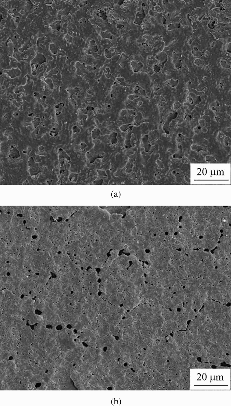
Images (SEM) showing surface morphologies of films treated in a bath A and b bath B
Figure 2 shows the cross-sectional morphologies of the TiO2 films formed in baths A and B. There was no appreciable distinction between the thicknesses of films formed in two different electrolytes: the thicknesses of both films were measured to be ∼6 μm. However, similarly to Fig. 1, it was observed that the TiO2 film formed in bath A revealed a very dense structure, while pores and voids were locally observed in the film formed in bath B as typical. Combining the two results, it is noteworthy that different plasma assisted electrochemical reactions were ineffective for the film growth even though they affected microstructures of cross-sections. This is due to the same reasons described above.
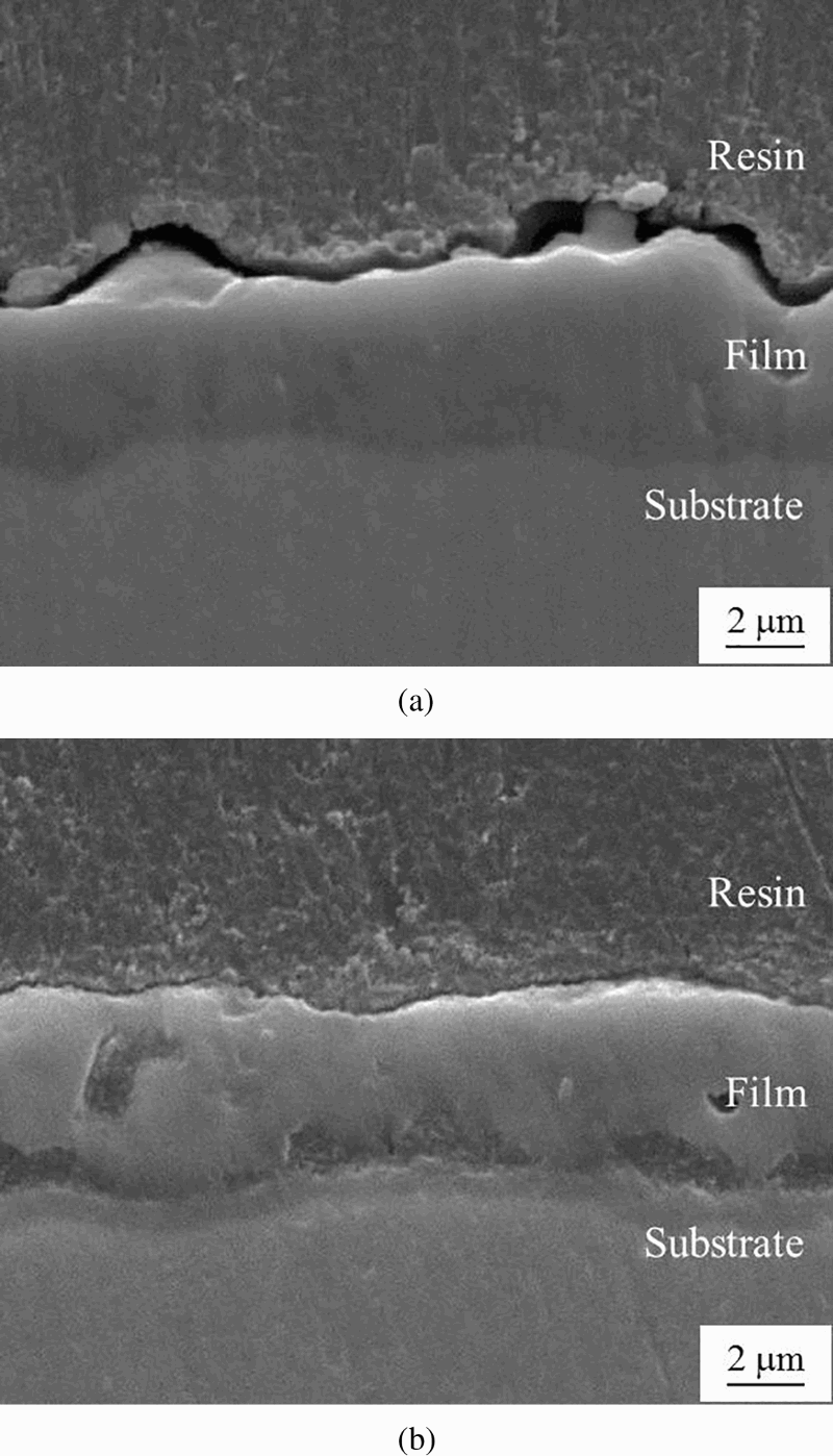
Images (SEM) showing cross-sectional morphologies of films treated in a bath A and b bath B
X-ray diffraction analysis was performed to investigate the constituent phases of the TiO2 films formed in baths A and B, and the results are shown in Fig. 3. TiO2 compounds, such as anatase and rutile, were detected in both conditions. Here, TiO2 was formed by electrochemical reactions between Ti4+ ions outward migrated from the substrate, and O2 − ions inward migrated from the electrolyte.
23
On the other hand, it is well known that anatase is generally identified as the more photochemically active phase of TiO2 owing to the lower rates of recombination and higher surface adsorptive capacity of anatase than that of rutile.
24
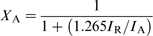
Therefore, the volume fractions of the anatase phase XA of both films were measured using the following equation
25
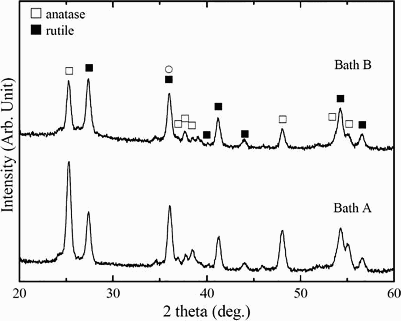
X-ray diffraction patterns of films formed in baths A and B
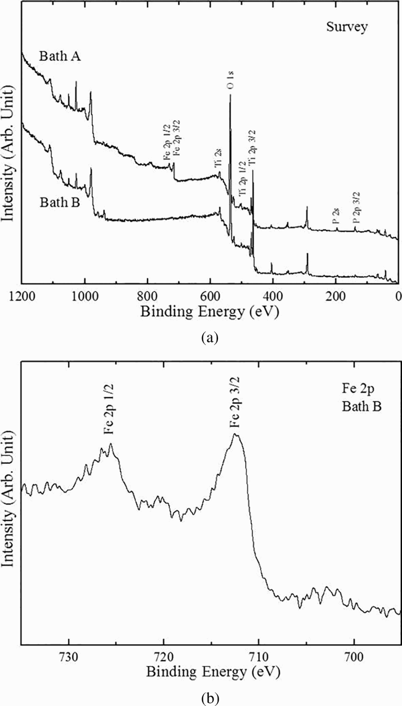
In order to confirm the valence states of chemical compounds present in the films formed in baths A and B, XPS analyses were conducted, and the results are shown in Fig. 4a. The peaks located at binding energies of 458.6 and 464.5 eV corresponded to Ti 2p 3/2 and Ti 2p 1/2 states of stoichiometric TiO2, which were related to the values of Ti4+ in the TiO2 compound.
26
The binding peak at 192.80 eV for P 2s was related to the formation of P2O5.
27
This compound might be formed in both TiO2 films due to the anodic oxidation of the decomposed
 ions in the electrolyte. As seen in Fig. 4b to ensure the presence of the Fe compound, the peaks of Fe 2p 3/2 and Fe 2p 1/2 in the TiO2 film formed in bath B showed that the binding energies of 712.80 and 724.00 eV were closely associated with FePO4 and Fe2O3 respectively.28,29 The presence of FePO4 and Fe2O3 compounds was attributed to the chemical components of the remaining electrolyte and the oxidation of Fe3+ ions onto the TiO2 film during the PEO process in bath B. Therefore, it is inferred that Fe2O3 was one of the chemical components for the film formed in bath B.
To analyse the optical properties of the TiO2 films formed in baths A and B, UV–vis diffuse reflectance spectra were obtained, and the results are shown in Fig. 5a. The reflectance ratio of the film formed in bath A was higher than that in bath B. Using the Kubelka–Munk equation,30,31 the band gaps of the TiO2 films were calculated as follows
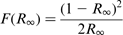

 is the Kubelka–Munk function, which is directly proportional to the absorbance (α),
 is the percentage of reflectance, n = 2 for an indirect allowed transition (TiO2) and A is a proportional constant. Figure 5b exhibited the relationship between
 and the photon energy of the PEO treated titanium samples, from which the extrapolated optical band gap was determined. The band gap of the TiO2 film formed in bath A was estimated to be ∼3.18 eV, which was higher than that in bath B (∼2.57 eV). According to the earlier investigation by Baiju et al.,
32
the band gap was independent of the surface morphologies. Thus, the main reason for the narrowing band gap of the film formed in bath B was attributed to the introduction of the Fe2O3 compound whose band gap energy is much low, although the volume fraction of anatase was higher in the film from bath A than that from bath B. This also implied that the adsorption edge of the film formed in bath B shifted to the long wavelength in the visible region so that this would extend the practical applications of the TiO2 film.
33
and the photon energy of the PEO treated titanium samples, from which the extrapolated optical band gap was determined. The band gap of the TiO2 film formed in bath A was estimated to be ∼3.18 eV, which was higher than that in bath B (∼2.57 eV). According to the earlier investigation by Baiju et al.,
32
the band gap was independent of the surface morphologies. Thus, the main reason for the narrowing band gap of the film formed in bath B was attributed to the introduction of the Fe2O3 compound whose band gap energy is much low, although the volume fraction of anatase was higher in the film from bath A than that from bath B. This also implied that the adsorption edge of the film formed in bath B shifted to the long wavelength in the visible region so that this would extend the practical applications of the TiO2 film.
33
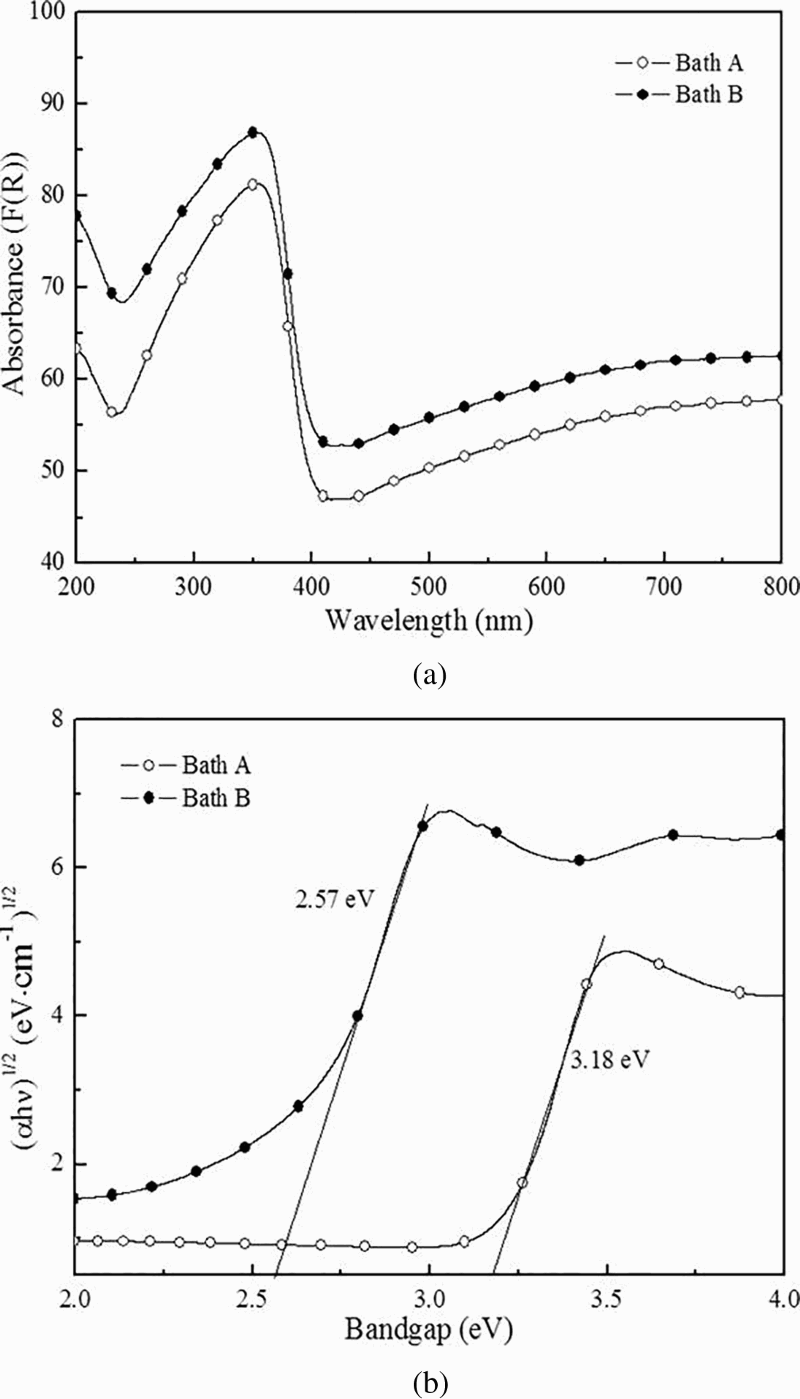
a ultraviolet–visible diffuse reflectance spectra and b (αhν)1/2 as function of photon energy of films treated in baths A and B
Figure 6 exhibits the photocatalytic activity of the TiO2 films formed in baths A and B for the degradation of methylene blue under the visible light illumination. The y-axis presented the ratio of the concentration of methylene blue at later time to the initial concentration of methylene blue at t = 0. In general, the photocatalytic activity of pure TiO2 could be inadequate under visible light conditions duet to its relatively wide band gap (∼3.2 eV). Accordingly, ∼19% of methylene blue was degraded on the film formed in bath A when the irradiation time was 270 min. For the credible evaluation, the degradation ratio was measured under the no light state to exclude the adsorption effect of surface pores, which results in that ∼16% of methylene blue was degraded on films formed in baths A and B. In other words, ∼3% of methylene blue could be degraded by photocatalysis of the films formed in bath A. On the other hand, in the case of bath B, the degraded concentration of methylene blue dropped to ∼92%. Thus, it was believed that the photocatalytic activity of the film under visible light illumination was enhanced by the incorporation of the Fe2O3 compound into the TiO2 film, resulting in a narrower band gap of ∼2.57 eV as compared to the present TiO2 film formed in bath A (∼3.18 eV).
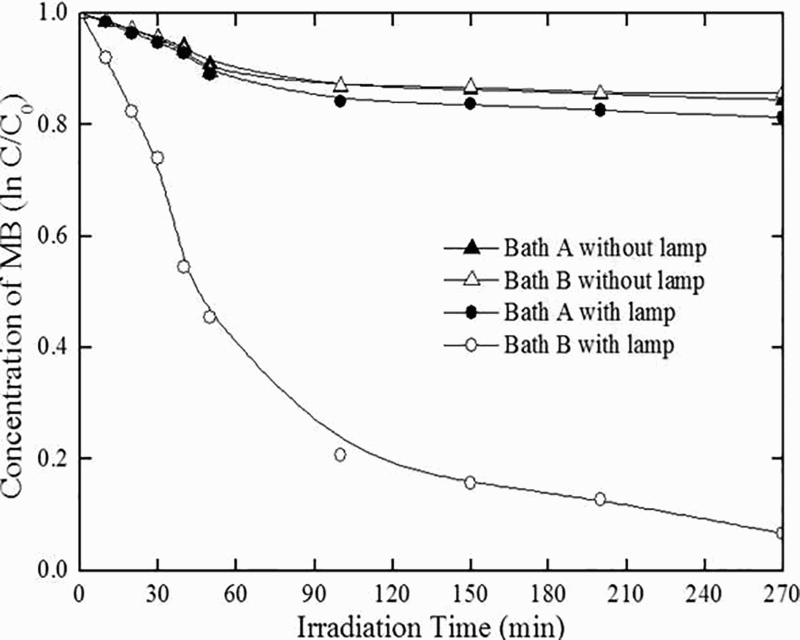
Concentration of methylene blue decomposed by films treated in baths A and B with irradiation time under visible light illumination
Conclusion
This study examined the photocatalytic activity of an Fe containing TiO2 film produced in the FePO4 electrolyte via the PEO process, and the optical properties were compared to that produced in the K3PO4 electrolyte. Depending on the electrolytes used in this study, the surface morphology of the mesoporous TiO2 film appeared to be varied by different plasma assisted electrochemical reactions that were largely affected by the electrolytes. It was confirmed by X-ray diffraction and XPS analyses that, when FePO4 electrolyte was used, the fraction of rutile phase of TiO2 was larger than that in the K3PO4 electrolyte and also the Fe2O3 compound formed newly in the TiO2 film. Hence, the band gap of the TiO2 film formed in the FePO4 electrolyte was observed to be as low as ∼2.57 eV. The optical results of photocatalytic activity in this study showed that ∼92% of methylene blue was decomposed over the entire surface of the TiO2 film formed in the FePO4 electrolyte under visible illumination exposed for 270 min, which was better than that in the K3PO4 electrolyte.
Footnotes
Acknowledgements
This work was supported by the BK21 Plus project of the National Research Foundation of Korea.