
Abstract
A dense and crack free MoSi2–ZrB2 coating was prepared on the SiC coated carbon/carbon (C/C) composites using a supersonic plasma spraying technique. The coated composites were characterised using scanning electron microscopy and X-ray diffraction. The analysis shows that the as prepared MoSi2–ZrB2 coating, with a thickness of ∼100 μm, combines well with the inner SiC coating. After oxidation at 1200°C for 72 h in air, the mass loss of MoSi2–ZrB2/SiC coated C/C is only 4.24 wt-%, which is significantly lower than that of MoSi2/SiC coated C/C (11.35 wt-%). The excellent oxidation protective ability of the MoSi2–ZrB2 coating is mainly attributed to ZrSiO4 produced by dispersive ZrO2 particles and SiO2 in the coating at high temperature.
Introduction
Carbon/carbon (C/C) composites have potential applications in the field of aerospace due to their attractive advantages including low density and excellent thermophysical properties at elevated temperatures. 1 Unfortunately, C/C composites are susceptible to oxidation above 500°C, which limits their applications in high temperatures and oxygen containing environments. 2 Coating technology is an effective approach to protect C/C composites against oxidation. 3 Usually, a SiC coating is synthesised on the surface of C/C composites as the bonding layer owing to its excellent antioxidation property and good compatibility with C/C. SiC also plays a positive role in relieving the mismatch of the coefficient of thermal expansion (CTE) between the C/C substrate and the outer ceramic coatings.4–6
Acting as the external protective coating of the C/C substrate, MoSi2 is a promising material that possesses excellent properties such as modest density (6.24 g cm− 3), high melting point (2030°C) and enhanced oxidation resistance at above 1500°C, even in some aggressive environments. 7 It has been widely used in heating elements and oxidation protective coating on SiC coated C/C composites.8,9 Nevertheless, MoSi2 has a problem of pest degradation below 700°C (Ref. 10 and shows a very low creep resistance below 1200°C due to a brittle to ductile transition at 900–1000°C, 11 which will induce crack and other defects as the temperature changes and thus further damaging the substrate. Therefore, it is important to improve the oxidation resistance property of MoSi2 at ∼1200°C to broaden its application.
Second phase doping is a logical way of improving the cohesion of the MoSi2 coating and obstructing the propagation of cracks in the coating. ZrB2 has the potential for use as the second phase due to its extremely high melting point and stability in extreme environment. 12 Moreover, during the oxidation process at high temperature, ZrO2 is produced by the oxidation of ZrB2, which will react with SiO2, and the oxidation product of MoSi2, to form ZrSiO4. 13 ZrSiO4 exhibits a series of attractive properties like low oxygen diffusion coefficient, high melting point and chemical stability in oxidative and corrosive environments. 14 It also has a CTE value close to that of SiC and could reduce the probability of generating cracks in the MoSi2 coating. Moreover, the glass zircon could provide good oxidation protection for the C/C substrate at high temperature. At present, many techniques have been applied on the deposition of MoSi2 and ZrB2 coating, such as pack cementation, 15 slurry painting 16 and plasma spraying. 17 Among the techniques, supersonic plasma spraying is a highly efficient method to deposit refractory material coating for commercial production. In this process, the accelerated melted particles were impinged on the surface of the substrate to form a compact coating. 18
In this work, a SiC inner coating was prepared on the C/C composites by pack cementation, and then a ZrB2 modified MoSi2 outer coating was prepared by supersonic plasma spraying. The effect of ZrB2 addition on the microstructure and oxidation protective property of the MoSi2 coating was investigated. The oxidation mechanism of the SiC/MoSi2–ZrB2 coating was also discussed.
Experimental
Specimen preparation
Acting as the substrate, the bulk 2.5D C/C composites with a density of 1.75 g.cm− 3 were cut into small cubes with dimensions of 10 × 10 × 10 mm. Then, the cubic specimens were hand-abraded with 80 grit SiC paper in order to remove the sharp edges and cleaned with absolute ethyl alcohol in the ultrasonic bath and dried at 80°C for 2 h.
Coating preparation
The inner SiC coating was prepared as a linking layer on C/C specimens by pack cementation. Details of the procedure were reported in our previous work. 19 The outer 80MoSi2–20ZrB2 (vol.-%) coatings were prepared by supersonic plasma spraying. The MoSi2 and ZrB2 raw powder was dry milled together for 1 h. Then, the polyvinyl alcohol (PVA) solution (PVA/water = 2–3 wt-%) was poured into the milled powders with the mass ratio of 1:1, and the mixed turbid liquid was evaporated at ∼120°C using a centrifugal rotary evaporator. The remaining powder was sieved by a 180 grit griddle for use in spraying.
The sieved powder was sprayed on the SiC coated C/C composites with a mixture of second gas H2 (4 L min− 1), primary gas Ar (75 L min− 1) and carrier gas Ar (10 L min− 1). The power applied in supersonic plasma spraying was 50 kW, the powder feedrate was 20 g min− 1 and the distance between the nozzle and specimens was ∼100 mm.
Characterisation
The isothermal oxidation tests of the prepared specimens were carried out in an electric furnace at 1200°C in air. The specimens were directly placed into the furnace and then taken out at the designated time. After the specimens were cooled to room temperature, their mass was measured by an electric balance with a sensitivity of ± 0.1 mg. Mass loss percentages were calculated according to equation (1)
Microstructure and composition of the surface and cross-section of the double layer coating before and after the oxidation were analysed by a scanning electron microscope (SEM, JSM-6460, JEOL Ltd, Mitaka, Japan) equipped with an energy dispersive spectrometer (EDS). The crystalline structure of the coatings was analysed by an X-ray diffraction instrument (XRD, X'Pert PRO, PANalytical, Almelo, The Netherlands).
Results and discussion
Microstructure of as prepared coatings
Figure 1 shows the SEM of the MoSi2–ZrB2 spray powder, and its average diameter is ∼50 μm. The powder is prepared through a rotary evaporation process, and a single particle consists of several smaller particles bound by PVA. The powder is spherical with some defects. Figure 2 shows the XRD patterns of the as sprayed MoSi2–ZrB2 coating and its raw powder, from which it can be seen that the powder before spraying is composed of MoSi2 and ZrB2. The sprayed coating mainly consists of ZrB2, MoSi2, Mo5Si3 and ZrO2. SiC in the bonding layer was also detected, which is due to the rough interface between the SiC layer and the sprayed coating. Mo5Si3 and ZrO2 were formed by the oxidation of raw materials during the supersonic plasma spraying process as the temperature of the plasma spray nozzle is ∼10 000°C, which is much higher than the oxidation temperature of MoSi2 and ZrB2. In the process of heating and speeding, the raw powder, MoSi2 and ZrB2 were partly oxidised according to equations (2)–(4)


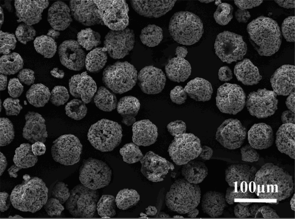
Surface morphology of MoSi2–ZrB2 spray powder
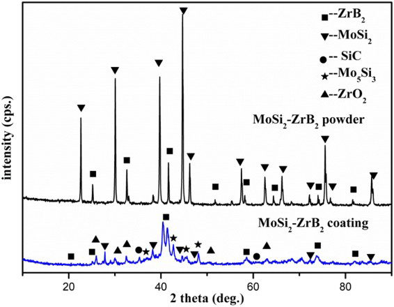
X-ray diffraction patterns of MoSi2–ZrB2 coating and its raw powder
Figure 3 shows the surface morphologies of MoSi2 and MoSi2–ZrB2 coatings before the oxidation test. From Fig. 3a, the surface morphology of the MoSi2 coating is rather homogenous without distinct pores or cracks. Figure 3b shows the enlarged view of the coating surface in Fig. 3a. There are plenty of well flattened lamellae along with some spherical features on the surface, which show a typical surface morphology of the coating prepared by supersonic plasma spraying. 21 During the process of coating preparation, high speed powders were heated by the plasma flame. The melted powder impinged on the surface of the substrate, forming a flattened surface structure. From Fig. 3c, it can be seen that there are a lot of pores and small bulges on the surface of the MoSi2–ZrB2 coating caused by the rushing out of entrapped carrier gas, MoO3 and B2O3. 22 From the cross-section of the MoSi2–ZrB2 coated SiC–C/C composites (Fig. 3d), it can been seen the MoSi2–ZrB2 and SiC coatings are compact, and the interfaces between these two coatings are continuous and mutually penetrated, and no visible crack can be observed, indicating a good combination of these two coatings. The MoSi2–ZrB2 outer coating is ∼100 μm in thickness. The SiC bonding layer is 100–250 μm in thickness, and part of the coating was infiltrated into the C/C substrate due to the porous structure of the C/C substrate and good fluidity of the powder during pack cementation.
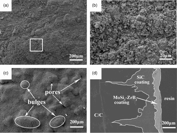
a surface morphology of MoSi2 coating, b enlarged view of a, c surface morphology of MoSi2–ZrB2 coating and d cross-section BSE morphology of MoSi2–ZrB2 coated SiC–C/C composites
Oxidation resistant property of coatings
Figure 4 shows the isothermal oxidation test results of the samples with MoSi2–ZrB2 and pure MoSi2 coatings at 1200°C in air. The sample with pure MoSi2 as an outer coating losses mass in a short time and the mass losing ratio accelerated over time. After oxidation for 72 h, the mass loss percentage reaches 11.35 wt-%. The sample with MoSi2–ZrB2 coating exhibits better oxidation resistance. At first, there is a mass gain for the first 30 h following which the mass decreases slowly. After oxidation for 72 h, the mass loss reaches 4.24 wt-%, which is less than that of the sample with pure MoSi2 coating. The oxidation test results indicate that a certain amount of ZrB2 could greatly improve the oxidation protective property of MoSi2 coatings at 1200°C in air


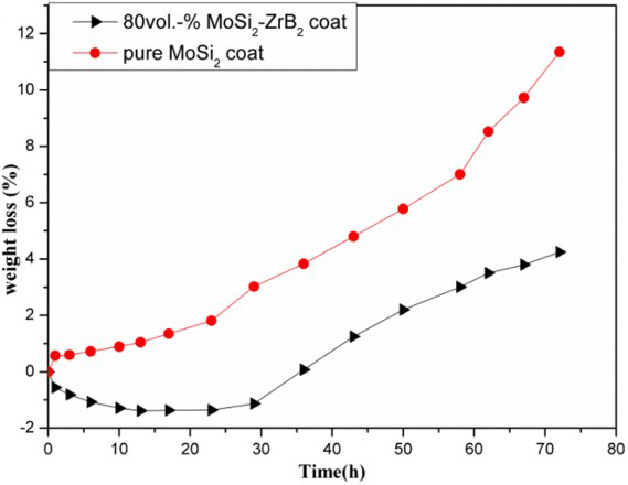
Oxidation curves of MoSi2–ZrB2 and pure MoSi2 coatings at 1200°C in air
Figure 5 shows the surface XRD patterns of MoSi2–ZrB2 coating and MoSi2 coating after oxidation at 1200°C in air for 72 h. It can be seen that the main phases of these two coatings are Mo5Si3 and some crystallographic SiO2. A ZrSiO4 phase exists only in the MoSi2–ZrB2 coating. The SiO2 phase was formed by the oxidation of silicide, such as MoSi2, Mo5Si3 and SiC according to equations (2), 3 , 5 and (6)), while the ZrSiO4 phase was formed by the reaction of SiO2 and ZrO2 according to equation (7)

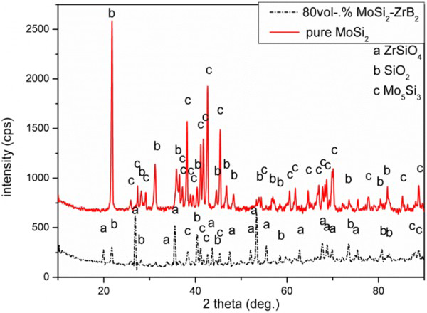
X-ray diffraction patterns of MoSi2–ZrB2 coating and MoSi2 coating surface after oxidation at 1200°C in air
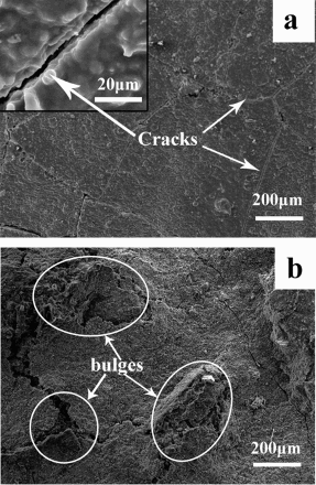
a surface morphology of MoSi2 coating after oxidation for 72 h at 1200°C in air and b surface morphology of MoSi2–ZrB2 coating after oxidation for 72 h at 1200°C in air
In Fig. 6b, there are several cracks and broken bulges on the MoSi2–ZrB2 coating. Some pores can be observed inside the bulges. Those bulges are formed due to the gas release. The oxidation behaviour of the MoSi2–ZrB2 coating shows a slow mass gain at the first stage due to the formation of ZrO2 according to equation (4). Then, ZrO2 reacts with SiO2 gradually to form ZrSiO4, which is a mass conservation reaction. At this stage, the mass loss was attributed to the oxidation of the MoSi2–ZrB2, which is accompanied by the evaporation of MoO3 and B2O3.
Figure 7 shows the cross-section BSE morphologies of MoSi2 and MoSi2–ZrB2 coatings and the EDS patterns of MoSi2–ZrB2 after oxidation at 1200°C in air for 72 h. From the cross-section of the MoSi2 coating shown in Fig. 7a, it can be observed that the SiC bonding layer separated from the C/C substrate, which has been oxidised severely. Some particles exist at the interface of the SiC bonding layer and the MoSi2 oxidation layer, due to the slight pest degradation of MoSi2 during the cooling and heating process. Additionally, there are some penetrating cracks caused by CTE mismatch between the inner and outer coatings. The horizontal cracks were induced by the thermal shock from 1200°C to room temperature to prove the poor cohesion of the MoSi2 coating. These defects provided channels for the oxygen to react aggressively with the inner coating and damage the C/C substrate, leading to a mass loss of the MoSi2 coating.
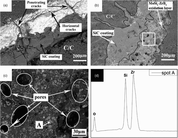
a cross-section BSE morphology of MoSi2 coating after oxidation at 1200°C in air, b cross-section BSE morphology of MoSi2–ZrB2 coating after oxidation at 1200°C in air, c enlarged view of white area in b and d EDS patterns of spot A in c
Figure 7b shows the cross-section of the MoSi2–ZrB2 coating after oxidation, and Fig. 7c is the enlarged view of the white area in Fig. 7b. The SiC coating remains intact and combines with the C/C substrate closely. After oxidation, the outer MoSi2–ZrB2 coating combines with the SiC coating well, and no visible cracks are observed. Its thickness increases to ∼200 μm, which was mainly resulted from the formation of large pores dispersed evenly in the outer coating. The pores are mostly formed due to the volatilisation of B2O3 and MoO3. From the XRD patterns (Fig. 5) and EDS (Fig. 7d) analysis, the white particles are ZrSiO4, and the grey phase is SiO2 mixed with some Mo5Si3. For the MoSi2 coating, there are many cracks in the coating. The gaseous MoO3 could flow out of the coating in time, and there is a discontinuous glass layer to obstruct the release of the gas. In the MoSi2–ZrB2 coating, there are not enough penetrating cracks to release the gas (B2O3 and MoO3) in time. At the same time, high concentration of ZrSiO4 particles produced in the coating acts as a barrier for gas to flow out of the coating. This caused a lot of big pores dispersed in the outer coating. Then, gradually, a small amount of gas in the pores was released and left the contact areas for oxygen, which induced a fast mass loss at ∼30 h during the oxidation test.
To clearly illustrate the oxidation mechanism of the MoSi2 and MoSi2–ZrB2 coatings, the schematic diagrams of their oxidation process are shown in Figs. 8 and 9. In Fig. 8a, some SiO2 glass covers the surface of the coating after oxidation for 72 h. A few vertical and horizontal cracks emerge and reach the inner SiC coating down to the C/C substrate as the oxidation continued (Fig. 8b). For the MoSi2–ZrB2 coating (Fig. 9a), some microcracks also propagated during the oxidation process (Fig. 9b). ZrO2 particles will be produced and dispersed around ZrB2 within the coating near the surface, and a SiO2 glass layer also formed and covered the coating. These ZrO2 particles are able to terminate the spreading of the cracks, restrict the generation of cracks and prevent the diffusion of oxygen, thus effectively protecting C/C composites from being consumed. The ZrSiO4 particle layer will be formed due to the reaction between ZrO2 and SiO2, as shown in Fig. 9c. It also covers the surface of the coating and heals microcracks, which make the coating more integral. The ZrSiO4 exhibits a low coefficient of oxygen diffusion and a similar CTE with SiC at 1200°C. They can not only decrease the diffusion of oxygen but also reduce the crack propagation resulting from thermal shock while cooling from 1200°C to room temperature. Therefore, ZrSiO4 produced by dispersive ZrO2 particles is significantly associated with the excellent oxidation protective ability of the MoSi2–ZrB2 coating.
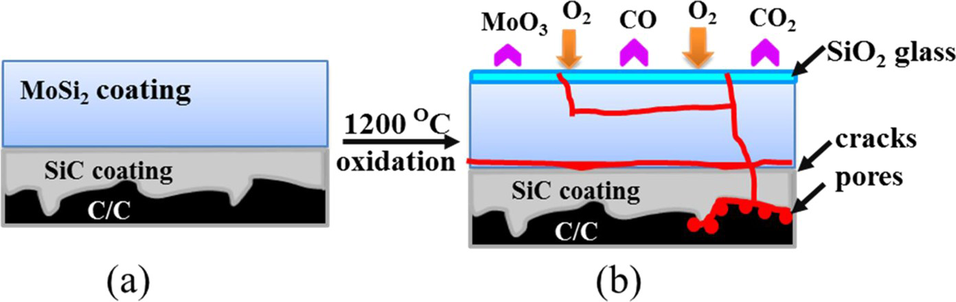
Schematics of oxidation process of MoSi2 coated SiC–C/C composites at 1200°C: a as prepared coating; b coating after oxidation
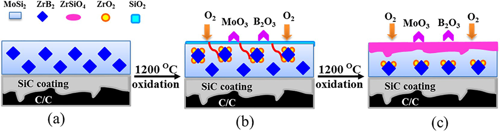
Schematics of oxidation process of MoSi2–ZrB2 coating at 1200°C in air: a as prepared MoSi2–ZrB2 coating; b coating during oxidation process; c coating after oxidation
Conclusion
Dense and crack free MoSi2 and MoSi2–ZrB2 coatings were prepared by supersonic plasma spraying on the SiC–C/C composites. The doping of ZrB2 in the MoSi2 coating could improve the oxidation resistant property of pure MoSi2 based coating, and the mass loss was decreased from 11.35 to 4.24 wt-% after oxidation at 1200°C for 72 h. The excellent oxidation protective ability is mainly attributed to a ZrSiO4 glass being able to heal cracks and decrease oxygen diffusion. The glass was produced by SiO2 and dispersive ZrO2 particles, which could restrict the spread of microcracks.
Acknowledgements
This work has been supported by the National Natural Science Foundation of China under grant nos. 51221001 and 51222207 and the project supported by the Research Fund of the State Key Laboratory of Solidification Processing (NWPU), China (grant no.12-BZ-2014).