
Abstract
This paper examines a series of fly ash and ground granulated blast furnace slag binders formulated to examine the effects of composition and mix design on performance and durability when exposed to aggressive environments found in carbon capture facilities (monoethanolamine or concentrated potassium carbonate, as well as distilled water). Ordinary Portland cement and ordinary Portland cement fly ash blends were examined for comparison. The samples are exposed to solvents by immersion under static conditions. Leaching and mechanical strength tests show a wide range of geopolymer performance, depending on the initial mix design and the nature of the aggressive agent. Alkali carbonate solutions are found to be the most aggressive agent among those tested in terms of geopolymer mass and strength loss; nonetheless, the resistance to structural degradation upon carbonation of the geopolymer binder structure is mitigated to a significant extent by the low calcium content of the geopolymer binder. Less porous materials, or materials with smaller and more tortuous pores, show in many cases a markedly higher durability; porosity is shown to hold the key to durability. In traditional cement based binders, strength is lost through chemical attack upon exposure to solvents.
Introduction
Geopolymer concrete is being proposed as a potential construction material in carbon capture and storage facilities, with its aluminosilicate chemistry suggested to provide the possibility of withstanding the harsh chemical environments found in post-combustion capture solvent columns.1–3 Geopolymers also offer ∼80% reduction in CO2 emissions relative to ordinary Portland cement (OPC)4 and utilise industrial wastes such as fly ash, which can bring appealing synergies in carbon capture applications. The chemical resistance of the geopolymer binder has previously been highlighted in laboratory testing over a number of years.1–3
The production of Portland cement, the key binder in almost all concretes currently used worldwide, contributes around 5–8% of anthropogenic CO2 emissions,5 with almost 1 t of CO2 released per tonne of cement produced. This rate of emission is becoming increasingly problematic as the demand for construction materials in the developing world continues to grow, and alternative technologies are necessary for the construction industry to become environmentally sustainable.
Carbon capture and storage options and facilities are currently being trialled in Australia, with viability depending strongly on the costs involved. Post-combustion carbon capture solvent columns, where CO2 from flue gas is collected by absorption into a solvent [e.g. monoethanolamine (MEA) or K2CO3], removed and stored, are currently constructed from stainless steel. The reported chemical resistance of geopolymers1–3 has led to the proposition that they may be able to provide a durable, cost saving ‘green cement’ alternative structural material that can resist exposure to the harsh chemical environments found within these systems.
Geopolymer concretes are synthesised by reacting industrial wastes (coal fly ash and/or metallurgical slags) with an alkali source to form the binder,6 blended with aggregates (sand and rocks) in a manner very similar to the development of concretes from Portland cement. This process utilises fly ashes, which are currently landfilled at a rate of several million tonnes per annum in Australia alone, and hundreds of millions of tonnes per annum worldwide. Along with environmental benefits, geopolymers may display the advantage of greater chemical resistance when compared to OPC systems, especially in the aggressive solvents used in carbon capture. An intermediate level of Ca content is provided by the addition of ground granulated blast furnace slag (GGBFS) to a fly ash geopolymerisation system. This has been shown to enhance the mechanical properties of the binder by the formation of a void filling, low Ca, Al substituted calcium silicate hydrate (C–(A)–S–H) gel in co-existence with the alkali aluminosilicate gel resulting from geopolymerisation. 7 7,8 The relatively low content and accessibility of calcium in the geopolymer binders are predicted to prevent the degradative effects of carbonation, which occur in traditional cement binders based on OPC. Carbonation has been shown to be reasonably rapid in some alkali activated binder systems,9 but the mechanism and influence on the binder structure differ significantly from the carbonation processes, which take place in OPC binders, with carbonation involving alkalis from the pore water as well as the C–S–H type gels, rather than the Ca(OH)2, which provides an alkalinity reservoir in OPC; the effect of carbonation on alkali activated mortars is also strongly dependent on the type of activator used.9–11
The resistance to relevant aggressive agents (water, alkali carbonates and amines) of various fly ash GGBFS geopolymer formulations is examined here, along with some comparison to OPC and OPC based composites, to assess the relative durabilities of these traditional cementing binders when exposed to equivalent chemical conditions.
Experimental
Materials
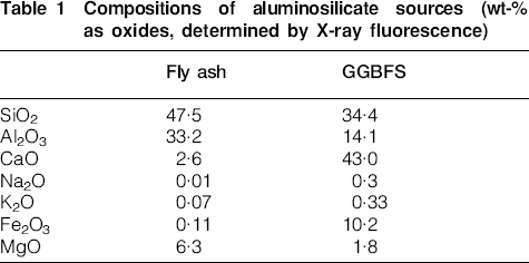
Fly ash was sourced from Gladstone Power Station, Queensland, Australia, and GGBFS and Portland cement (type GP) were obtained from Independent Cement & Lime, Australia. Table 1shows the component oxide ratios for the aluminosilicate sources used. The sodium silicate activating solution had a composition (mass basis) of 28·7%SiO2, 8·9%Na2O and 62·4%H2O.
Compositions of aluminosilicate sources (wt-% as oxides, determined by X-ray fluorescence)
Methods
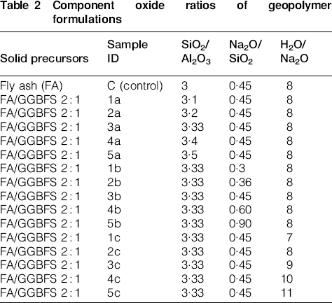
A series of 16 geopolymer samples were examined; 15 samples with a fly ash/GGBFS ratio of 2∶1 and a pure fly ash binder as a control sample. NaOH and H2O were added to commercial sodium silicate to give the activating solution oxide ratios shown in Table 2. Geopolymer samples were cured for 48 h at 40°C and then a further 5 days at ambient temperature, all under sealed conditions, before exposure to aggressive environments.
Component oxide ratios of geopolymer formulations
Additionally, three OPC pastes were mixed with a water/solid ratio of 0·3, and different ratios of blending: pure OPC, 3∶1 FA/OPC and 3∶1 BFS/OPC. These were cured for 7 days at 40°C and subjected to the same examinations as the geopolymer samples.
Leaching analysis was carried out using cylindrical sections of each sample (2 cm in diameter, aspect ratio of ∼1) in the form of a hardened paste. A solid section with ∼15 g weight was submerged in 200 mL of each carbon capture solvent: 98%MEA, 2·5M K2CO3 or distilled H2O. An aliquot of 1 mL of solution was removed after 1, 3, 7, 14, 28 and 90 days. The volume of leachate removed was replaced with fresh solvent, and a pH measurement was taken at each sampling. The leachate was diluted 10 times with 10%HCl and analysed by inductively coupled plasma–optical emission spectroscopy to determine the quantities of Al and Si present.
For strength testing, mortars were made from each formulation, with the addition of quartz sand, at a 3∶1 volume of sand to aluminosilicate solids. These samples were placed in 50 mm cubic moulds, cured at 40°C for 48 h and then held at ambient temperature until testing. After 7 or 28 days, triplicate samples were analysed for compressive strength.
Mortar cube samples were also subjected to the same 7 days aging regime described above and then immersed in the solvents (98%MEA, 2·5M K2CO3 and distilled water) for 28 days before being analysed for compressive strength; again, there were three repeats for each sample, and the mean result was taken.
To assess the effect of solvent exposure on the solid matrix, the samples were characterised using X-ray diffraction (Bruker D8 Advance), carbon coated and polished using scanning electron microscopy (FEI Quanta) and N2sorption porosimetry (Micromeritics Tristar 3000).
Results
Mechanical strength
Figure 1 shows the mechanical strengths of each of the fly ash formulations after 28 days of unexposed aging and after 7 days of curing and then 28 days of solvent exposure. Strength was lost by almost all the exposed samples. Because the samples were cured for only 7 days before immersion, and the glassy nature of the fly ash particles results in relatively slow reactivity, these relatively immature pastes showed low resistance to chemical attack; most of the matrixes failed following 28 days of exposure to K2CO3. However, MEA resistance was high. In addition, in the few samples where strength was retained following exposure to K2CO3 (2b, 3b, 1c, 3c, 4c and 5c), resistance appears high with only a small strength loss relative to that of the unexposed sample.
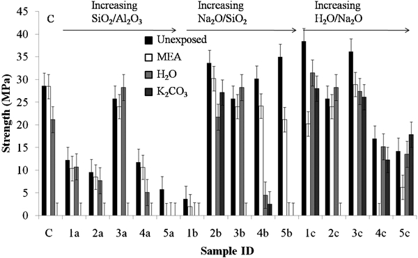
Mechanical strength of fly ash formulations after 28 days of solvent exposure
The sample with a pure fly ash binder, labelled C, was resistant to MEA and had some strength loss when exposed to distilled water, but did not retain any strength when exposed to K2CO3. This control sample had unexposed strength equivalent to many of the FA/GGBFS binders, which may be due to the low SiO2/Al2O3 ratio (3·0) and increased availability of Al for geopolymerisation. Aluminate species promote condensation reactions in geopolymer systems, 12 12,13 and thus, the availability of Al from the precursors is an important factor in determining the final properties of the binder.14However, for the sample series 1a–5a, which had increasing SiO2/Al2O3ratio, both unexposed and residual strengths are low in all of these formulations with the exception of sample 3a. The release of aluminate species from fly ash is slow due in part to the tendency of the Al to segregate into mullite phases rather than being solely located in the more reactive alkali silicate glasses.15 In the presence of (low Al) GGBFS, the increase in silicate content across this series does not lead to a marked strength reduction, with the exception of sample 5a, which has the highest concentration of silicate in solution. It seems from this series that an optimal formulation (in terms of 28 days strength development) is found with sample 3a, with an overall SiO2/Al2O3ratio of 3·33. It is noted that the optimality of this ratio will be specific to the activation conditions and precursors used here; the optimal SiO2/Al2O3 ratio will depend in particular on the mineralogy of the fly ash and the concentration of the alkali activator.
Samples 1b–5b are designed with an increasing Na2O/SiO2ratio across the series (and thus also increasing water content, as the H2O/Na2O ratio was held constant). 1b has a low alkalinity, and so its strength is lower due to a lower extent of dissolution of the aluminosilicate phases on mixing and the formation of a more porous gel microstructure at low alkalinity.16 Unexposed strength is relatively high through the rest of the series, despite the increasing water content. However, exposure to either water or K2CO3, and to a lesser extent MEA, is increasingly damaging to the matrixes with increased NaOH and water content. This is likely to be due to a combination of the increased water content and the reduced SiO2 content of the activating solution, both of which will lead to an increased gel porosity. There is a gradual decrease in original and residual strength through samples 1c–5c again due to the increased water content and greater porosity.
Mechanical strength tests were also carried out on the three OPC containing samples (pure OPC binder, 3∶1 FA/OPC and 3∶1 BFS/OPC), following 7 and 28 days of aging and 28 days of exposure to each solvent. Figure 2 shows that strength increased significantly between 7 and 28 days of age, as is expected due to the continuing hydration reactions, particularly for the high volume slag and fly ash blends.
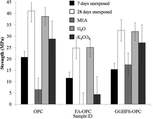
Strengths of OPC formulations with age and 28 days of solvent exposure
A similar increase would be expected in well cured geopolymer concrete.17 In addition, as expected, the samples all retained strength when submerged in water; the exposure of alkali activated binders to distilled water was detrimental due to alkali leaching. The OPC containing samples had low resistance to MEA, with complete failure of the matrix observed in the fly ash–OPC blend, and little residual strength in the pure OPC binder. The BFS–OPC blend had somewhat greater resistance to MEA, although significant strength was lost.
Both OPC and the BFS–OPC binder showed reasonably high resistance to K2CO3, although it is possible that not enough time had elapsed for significant carbonation to occur. The low strength gain of the FA–OPC by 28 days is due to the slower rate of reaction of fly ash than cement. The samples all had the same water/solid ratio (0·3), but the lower water demand of fly ash resulted in a relatively fluid mix, and this, along with the low extent of reaction, may also have resulted in a high porosity binder. This increased porosity and permeability may have promoted carbonation relative to other formulations, which accounts for the low residual strength following exposure to K2CO3. It is expected that further exposure of the OPC and 3∶1 BFS/OPC binder to K2CO3 would lead to a further reduction in strength as carbonation occurs and causes degradation.
Leaching
Figure 3, which shows the leaching of both Si and Al from all of the fly ash formulations in each of the three solvents, does not display sample specific data. However, it gives an overall view of the performance of each binder with respect to each solvent. There is high resistance to MEA, with generally <1%Si and Al leaching in this solvent, but a markedly higher extent of leaching in both K2CO
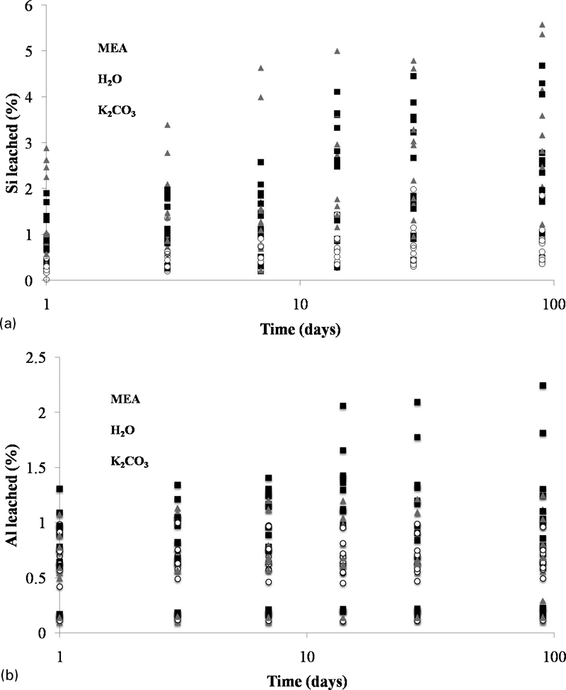
In situ leaching of a Si and bAl from fly ash/GGBFS formulations after solvent exposure
Leaching occurs rapidly, and the dissolved concentrations of both Si and Al are reasonably high after just 1 day of exposure to all solvents. There is then a further gradual release of Si and Al with time. The pH exceeded 12 at 1 day of exposure in all solvents and remained at this level throughout the duration of the study. Loosely bound Al is likely to be present within these samples, which were cured for a relatively short time (7 days), and so have an underdeveloped microstructure. This was a key part of the experimental design, as the aim of these experiments was to determine the relative effects of each of the solvents on the different mix designs rather than specifically tailoring the mix design and curing conditions for optimal resistance to the solvents. If the samples were designed to maximise resistance to leaching during the test programme, then the data obtained would not be particularly instructive, as the observation of uniformly low leaching rates would give little basis for distinguishing the effects of different mix design parameters or environments.
X-ray diffraction
The X-ray diffraction data for sample 1c, which had both high original and relatively high residual strength on exposure to solvents, are shown in Fig. 4. The major crystalline phases present are mullite, haematite and quartz, unreactive components of the fly ash used. There was also a zeolite phase, identified as chabazite-Na (powder diffraction file no. 31-1271), formed in the unexposed binder (as is quite commonly observed in fly ash geopolymers), which remains in the samples exposed to MEA and H2O. These strong peaks remain following exposure to K2CO3; however, there is a slight peak shift to lower 2θ thought to be due to the ion exchange of K+ for Na+in the structure. Carbonation, with the formation of calcite (CaCO3), has occurred in the binder phase following exposure to both distilled water and K2CO3, which may account for the strength loss observed (Fig. 1). The ‘hump’ between about 26 and 35° 2θ shows the presence of amorphous material, which may be in the form of the tetrahedral aluminosilicate geopolymer gel products and/or a low Ca C–S–H binder. The immaturity of these pastes before immersion has resulted in binders that are vulnerable to chemical attack, with the release of loosely bound Al and accessibility of the Ca within the binder phase, as shown by the significant carbonation.
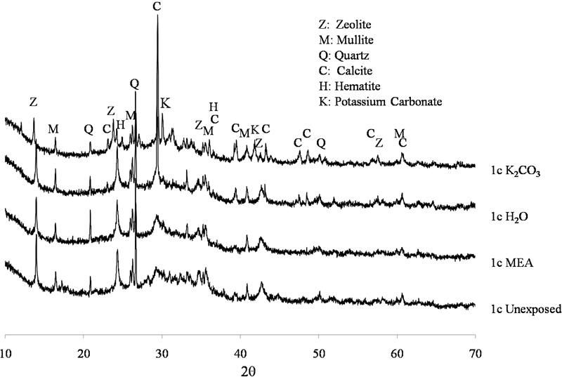
X-ray diffractograms of sample 1c unexposed and after exposure to solvents
Significant carbonation has also occurred in the 3∶1 BFS/OPC sample (Fig. 5) upon exposure to both distilled water and K2CO3, as expected, with the formation of both calcite and aragonite. The unexposed sample also has some carbonation, with the aragonite polymorph appearing to dominate calcite formation in this binder. The many small peaks, especially between 30 and 50° 2θ, correspond to the unreacted calcium silicate phases of OPC. Ettringite has formed on hydration and remains following exposure to H2O and K2CO3 but has disappeared after exposure to MEA. Gehlenite, the unreactive crystalline component of slag, is also notable in all samples; it was probably present also in the geopolymer samples shown in Fig. 4 because it does not react significantly during geopolymerisation but is not easily identified due to the lower slag concentration in the geopolymer samples. The unreacted calcium silicate phases of OPC and the majority of the carbonates have disappeared following exposure to MEA, explaining the significant strength loss occurring in all three of the OPC systems via a decalcification mechanism.
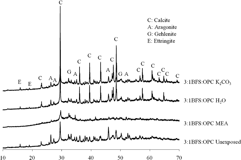
X-ray diffractograms of 3∶1 BFS/OPC, unexposed and after exposure to solvents
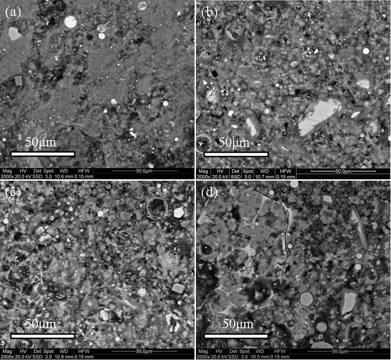
Backscattered electron images of polished sections of sample 1c aunexposed and exposed to b MEA, c H2O and d K2CO3
Scanning electron microscopy
Figure 6 shows the backscattered electron images of sample 1c. The geopolymer microstructure consists of a porous binder, which appears to increase in porosity and pore size on exposure to solvents, indicating that significant chemical attack has occurred in the binder phase.
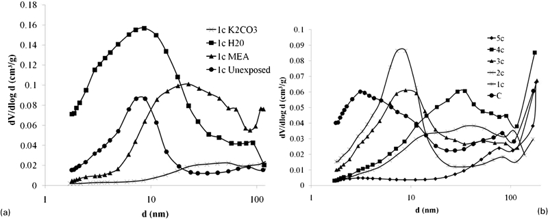
Pore size distributions in a sample 1c unexposed and following solvent exposure and b samples 1c–5c unexposed
Porosity
Porosimetry data were obtained by nitrogen sorption on powder samples. Figure 7ashows the mean pore size distributions of sample 1c unexposed and after 28 days of solvent exposure calculated by the Barrett–Joyner–Halenda method. There is a general trend towards an increased mean pore size at a greater diameter after exposure to solvents, which correlates with the strength losses shown in Fig. 1. It should be noted that the Barrett–Joyner–Halenda technique as implemented here cannot accurately measure pore diameters in excess of 200 nm, which appears to be the primary pore size range present in the sample exposed to K2CO3. Chemical attack on the matrix has increased the porosity, resulting in reduced strength relative to the unexposed sample. The structure of the sample exposed to K2CO3shows the most marked alteration, with the movement most of the pore volume into a size range too large to be accurately measured by nitrogen sorption analysis. Exposure to MEA has raised the mean pore size and diameter range, with a larger distribution of pores found between 10 and 100 nm diameter. Exposure to high pH water (the initially distilled water systems, but which became alkaline due to alkali leaching from the geopolymer samples) has not increased the mean pore diameter but rather increased the number of pores at this diameter relative to the unexposed samples. All of the samples lost strength during exposure as a result of this altered pore distribution, tending towards increased porosity. Figure 7b shows the pore size distributions of the sample containing the pure fly ash filler (sample C) and the series formulated with increasing H2O/Na2O ratios (1c–5c). There is a general trend towards a greater porosity and a higher mean pore size through the series as a result of the increased water content. Supported by the strength data (Fig. 1), this shows that porosity holds the key to durability.
Conclusion
Geopolymer cements may provide an alternative construction material to costly stainless steel in carbon capture facilities. This study made use of immature, porous geopolymer binders in order to accelerate and therefore understand the mechanism of chemical attack on exposure to carbon capture solvents. The key to durability for geopolymer systems is achieving and maintaining a low porosity, as demonstrated by the improved performance of the samples designed with lower water contents. Reducing the accessibility to key binder phases, especially the void filling, low Ca C–S–H, is central to ensuring the durability of geopolymer binders; the performance of OPC based pastes exposed to these environments shows that the inability to retain Ca in those systems is the key reason for strength loss. Matured, low porosity geopolymer binders may prove durable in these harsh aqueous environments, and the data presented here regarding the degradation mechanisms and causes of durability will provide key steps in this direction.
Footnotes
Acknowledgements
The authors acknowledge the funding provided by the Australian government through its CRC Program to support this Cooperative Research Centre for Greenhouse Gas Technologies research project, and L. Cao at the University of Melbourne for providing the porosity data.
This paper is part of a special issue on Cement and Concrete Research