
Abstract
Ceramics materials of the class of spinel nanoferrites of Mn1−xNixFe2O4 (x = 0·00, 0·025, 0·50, 0·75 and 1·00) of 13–25 nm particle sizes have been investigated for their electrical and dielectric characteristics. The dc electrical resistivity was measured and found to decrease with an increase in x to follow the Verwey mechanism because of the increase in electron hopping between the Fe2+ tetrahedral site (A site) and the Fe3+ octahedral site (B site). In addition, the resistivity of ferrites was observed to decrease with an increase in temperature, confirming their semiconductor characteristics. The dielectric constant and the dielectric loss factor were found to decrease as the frequency increased, following the Maxwell–Wagner interfacial type of polarisation. The study of the electrical properties of the prepared ferrites suggests their usefulness in important applications in electronic devices in reducing power losses due to an increase in conductivity caused by the increment in Ni concentrations in various electronic circuitries, such as those in computers and transformer coils.
Keywords
Introduction
The advent of nanotechnology has generated renewed interest in the study of the synthesis, functionalisation, structural, electrical and magnetic properties of an important class of ceramics materials, known as spinel ferrites.1 These studies assist in understanding the chemical and physical properties to tailor these materials for modern nanotechnology applications in a large number of devices and components.2 Considering these, to obtain desirable electrical and dielectric characteristics of the ferrites, research efforts have been made to develop and study various combinations over the years by incorporating metal cations such as Mn, Ni, Co, Cu and Zn.3 The current work is also part of our continuous efforts to study the electrical characteristics of nanoparticles of manganese–nickel spinel nanoferrites of Mn1−xNixFe2O4 with varying nickel concentrations: x = 0·00, 0·25, 0·50, 0·75 and 1·00. Our recent work has described in detail the synthesis, structural and magnetic characteristics of these Mn1−xNixFe2O4 nanoferrites.4 The crystallised sizes of the spinel ferrites measured by X-ray diffraction were found in the range of 13–26 nm, and the lattice constant a decreased with an increase in Ni concentration x. In the present work, we further investigated the prepared nanoferrites to describe their electrical and dielectric characteristics. The study of these characteristic is important due to several reasons. First, most of the fundamental properties of ferrites based on Mn or Ni are made of simple binary alloys such as MnFe2O4 or NiFe2O4.5, 6 On the other hand, most of the commercially important ferrites are ternary alloys of mixed variety, and in this category, again, most of the published works described Mn–Zn and Ni–Zn ferrites able to attain high resistivity as well as high initial permeability.7, 8 These ferrites are usually marked under the trade name Ferroxcube, and the presence of Ni or Mn along with Zn enables these to be used in a wide variety of applications, such as a core for receiving antennas and inductors, wide band and pulse transformers, cores of recording heads and several components of television set and portable radio.9, 10 Second, several reports are available on the magnetic and electrical properties of the nanocrystalline binary alloy of MnFe2O4 and NiFe2O4 and its ternary alloy, such as NiZnFe2O4 and MnZnFe2O4. On the contrary, to the best of our knowledge, other related ferrites of the type of MnNiFe2O4 have not yet been investigated in much detail, and detailed electrical and dielectric properties of nanocrystalline spinel ferrites of MnNiFe2O4 are lacking. Finally, the dielectric properties of Mn1−xNixFe2O4 for a whole range of Ni concentration x and frequency have not been reported before to reveal their influence on the characteristics of these nanoferrites. Therefore, it would be interesting to explore the effect of substitution of Mn or Ni ions in Mn1−xNixFe2O4 for the whole concentration range on the electrical characteristics of these nanoferrites. This is because with the variation in the Ni2+ and Mn2+ concentrations, the resident amount of Fe2+ and Fe3+ ions on the tetrahedral and octahedral sites in the lattice structure can be rearranged to subsequently influence the electrical characteristics of Mn1−xNixFe2O4 ferrites.
Keeping in view the above mentioned factors, the principal motivation of this work was to further study the prepared nanoferrites of Mn1−xNixFe2O4 and describe in detail the specific influence of varying Ni concentrations x (x = 0·00, 0·25, 0·50, 0·75 and 1·00), different temperatures (373–573 K) and frequency (0·1–5 MHz) dependence on their electrical and dielectric properties. The detailed study reported here offers valuable information about the mechanism of electrical resistivity and conduction in the prepared Mn–Ni nanoferrites, which, in turn, help to explain their electrical characteristics, such as dc resistivity, influence of varying Ni concentrations x, different temperatures, activation energy and drift mobility. In addition, the present work also investigated the prepared nanoferrites of Mn1−xNixFe2O4 considering the effect of the applied frequency on their dielectric properties, such as dielectric constant ϵ′, dielectric loss ϵ″, dielectric loss factor tan δ and ac conductivity σac. The study of the dielectric characteristics indicates that the properties of Mn–Ni ferrites are strongly influenced by the applied frequency. In order to gain an insight into the properties of the prepared ferrites, dielectric behaviours are evaluated, and the results are correlated to the varying applied frequency regimen of 0·1–5·0 MHz.
Experimental
Previous work described in detail the synthesis by chemical coprecipitation procedure and structural and magnetic characterisation of a series of Mn1−xNixFe2O4 (with x = 0, 0·25, 0·50, 0·75 and 1·00) spinel nanoferrites.4 Briefly, coprecipitation reactions yield ferrites in powder form, which were sintered at a temperature of 800°C for 5 h, and the prepared nanoferrites were characterised by X-ray fluorescence, X-ray diffraction, infrared spectroscopy, scanning electron microscopy and atomic force microscopy to study the compositional, structural and morphological changes taking place with varying Ni concentrations x. In addition, magnetisation measurements were made using a commercial vibrating sample magnetometer.4 The present work specifically focuses on the study of the electrical and dielectric characteristics of the previously well characterised nanoferrites. Electrical and dielectric parameters of the prepared ferrites were calculated using the standard relationship as described elsewhere and discussed below.11, 12
The dc electrical resistivity ρdc was measured with a custom made two probe method set-up in the temperature range of 373–573 K for various compositions of Mn–Ni nanoferrites. Disc shaped samples of ∼8 mm diameter and 3 mm thickness were used for the measurements. Standard Arrhenius relation in accordance to equation (1) was used to obtain the dc electrical resistivity ρdc at specific temperatures. From the slope of the Arrhenius plot, the activation energy data were obtained as follows13
Drift mobility μd was calculated using the standard relationship in accordance to equation (2)14


The dielectric constants ϵ′ were measured at room temperature in the frequency range of 0·1–5·0 MHz using an LCR Meter Bridge (model HP 4284 A) in accordance with the relation described in equation (4). For this purpose, circular discs from the powder of the prepared nanoferrites were made, and then a silver coating on the adjacent faces was applied to obtain the parallel plate capacitor geometry with the sample materials as the dielectric medium

The dielectric loss tangent tan δ as a function of frequency was studied at room temperature, i.e. 373 K. The dielectric loss tangent tan δ values were obtained from the standard relation given in equation (5)11,
12

Using the dielectric constant ϵ′ and the dielectric loss tangent tan δ values, the ac conductivity σac of the prepared samples was calculated at an angular frequency ω in accordance to relation (6)16

Results and discussion
The electrical and dielectric properties of the prepared ferrites of Mn1−xNixFe2O4 (x = 0·00, 0·25, 0·50, 0·75 and 1·00) have been investigated, and the results are summarised in Table 1 and discussed below.
Summary of results of electrical and dielectric properties of nanoparticles of Mn1−xNixFe2O4 ferrites for Ni concentrations x = 0·00, 0·25, 0·50, 0·75 and 1·00*
*Values of various parameters are given such as dc electrical resistivity ρdc, activation energy ΔE, correlation coefficient R, drift mobility μd, dielectric constant ϵ′ and tangent loss factor tan δ. Values of average particles size tave are also summarised for various compositions of prepared Mn–Ni nanoferrites.4
Electrical properties
Direct current electrical resistivity
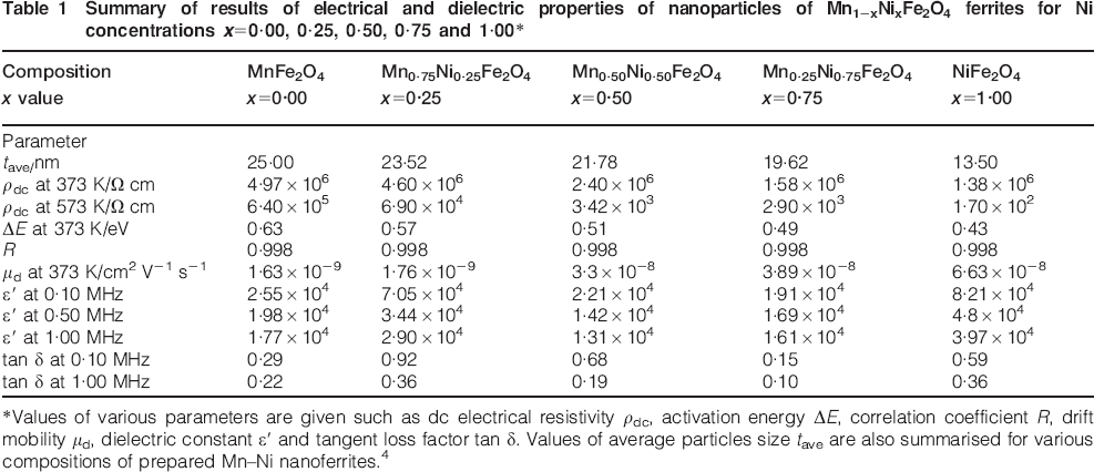
In general, an increase in temperature results in an increment in the resistivity of metals, while the semiconductor exhibits the opposite behaviour with temperature. The prepared nanoferrites of Mn1−xNixFe2O4 are insulators to exhibit semiconductor-like characteristics with the increase in temperature. The resistivity behaviour is investigated in the temperature range of 373–573 K considering the influence of Ni concentrations x = 0·00, 0·25, 0·50, 0·75 and 1·00 in the nanoferrites of Mn1−xNixFe2O4. Table 1 summarises the electrical properties of the nanoferrites of Mn1−xNixFe2O4. The electrical resistivity behaviour of the prepared nanoferrites of Mn1−xNixFe2O4 with varying nickel concentrations x was observed to follow the Arrhenius relation in accordance with equation (1), as presented in Fig. 1.
Linear dependence of temperature on electrical resistivity ln ρdc in accordance to Arrhenius plot for nanoferrites of Mn1−xNixFe2O4 (x = 0·00, 0·25, 0·50, 0·75 and 1·00): straight lines are best fit to equation (1); inset graph shows resistivity as function of temperature at various Ni concentrations x
It is well known that the electrical resistivity ρdc of ferrite decreases with an increase in temperature, thus confirming the semiconductor nature of the prepared nanoferrites in the present work.17, 18 This observation is attributed to the increase in the thermally activated drift mobility μd of charge carriers in accordance with the conduction mechanism of the hopping of electron.19 In the hopping conduction mechanism, the charge carrier's mobility is temperature dependent, and the band gap between the conduction band minima and the valence band maxima can be tuned by an appropriate choice of a dopant. The latter characteristics are clearly exhibited by incorporating Ni in the prepared nanoferrites and are indicated by the decrease in resistivity as the x content is increased. The observed extent of variation in ρdc in the current work was also found to be highly dependent on temperature. The variation in resistivity of the prepared ferrites is in agreement with related studies on ferrites, which indicated that the addition of Mn resulted in the enhancement of resistivity.20–22 The above mentioned observations regarding ρdc in the prepared nanoferrites can be explained by considering the Verwey mechanism due to electron hopping between the Fe2+ tetrahedral site (A site) and the Fe3+ octahedral site (B site),23, 24 i.e. cations that are capable of promoting the increment in this transition, thus resulting in increases in the conduction. Therefore, the observed decrease in dc resistivity ρdc with the increase in Ni may be attributed to the presence of relatively higher electron hopping between Fe2+ ions in A sites and Fe3+ ions in B sites. Improvements in the resistivity upon increment in Mn contents appeared to be the replacement of the Fe2+–Fe3+ conduction mechanisms by a more complex conduction mechanism. Presumably, replacing Fe and/or Ni ions with the addition of Mn ions seems to eliminate the easy conduction paths otherwise provided by the former ions.
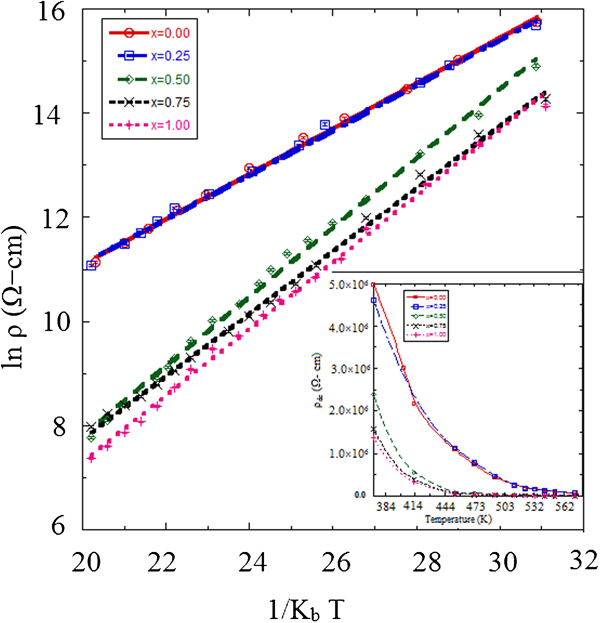
By taking the inverse of the experimentally determined values of ρdc, it is convenient to calculate dc electrical conductivity σdc using the σdc = 1/ρdc relationship. In order to illustrate the temperature dependence of σdc, a representative example is presented in Fig. 2 for Mn0·50Ni0·5Fe2O4. As indicated, it seems that there are two straight lines that suggest two different activation energies for Mn–Ni ferrites. The line changes its slope at the temperature of ∼452 K, which is known as the Curie temperature Tc. It was reported that a change in the gradient of the straight line must take place on passing through the Curie point. The magnitude of this gradient effect depends on the ions’ exchange interaction, which then subsequently determines the Curie point Tc.25, 26 The activation energies ΔE for electrical conduction are calculated from the slopes of lines on both sides of Tc and in the low temperature found to be within the range of 0·466–0·544 eV and in the high temperature regions between 0·707 and 0·884 eV.
Representation of dc conductivity against temperature for Mn–Ni nanoferrites of Mn0·50Ni0·5Fe2O4
Activation energy ΔE
Activation energy is needed to release an electron from the ion for a jump to a neighbouring ion, hence giving rise to the electrical conductivity. In the current work, ΔE values were also determined using equation (1) from the slopes of the Arrhenius relationship in the linear plots of ln ρdc against 1/kBT given in Fig. 1, and the values are summarised in Table 1. The ΔE values were found to decrease approximately linearly as the Ni concentrations x increase in Mn1−xNixFe2O4 and therefore resulted in an enhancement of conductivity or a decrease in resistivity. This observation is presented in Fig. 3 as a function of Ni concentration x along with dc resistivity. The values of ΔE decreased from 0·63 to 0·43 eV, corresponding to a ∼47% change as the Ni concentration increased from 0·0 to 1·0. This shift in ΔE is attributed to the above mentioned discussion of the decrease in ρdc with the increase in Ni concentration because the activation energy behaves in the same way as that of resistivity. In ferrites, the activation energy is not dependent on the concentration of charges but is associated with the variation in the charge carrier's mobility localised at the ions or vacant sites to give electrical energy to overcome the barrier experienced by the electrons during the process of conduction via the hopping mechanism.19 Since, in the prepared ferrites, ΔE values were found to be >0·4 eV, this observation therefore suggests that the conduction is due to polaron hopping.27
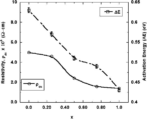
Effect of Ni concentrations x = 0·00, 0·25, 0·50, 0·75 and 1·00 on dc resistivity ρdc and activation energy ΔE (eV) of nanoferrites of Mn1−xNixFe2O4
Drift mobility μd
The drift mobility μd is a proportionality factor between the drift velocities of charge carriers in a semiconductor and electric field. Figure 4 represents the effect of temperature on the drift mobility μd for various Ni concentrations x in Mn1−xNixFe2O4. It is evident that nanoferrites having higher resistivity are exhibiting higher drift mobility μd for various compositions. In accordance with the hopping model, the electron–photon interaction induces strong localisation of electron on the cations.28 The increase in μd with temperature may be due to the enhancement of charge carriers, which start hopping from one site to another site by the increase in temperature, as explained above for the dc electrical resistivity.
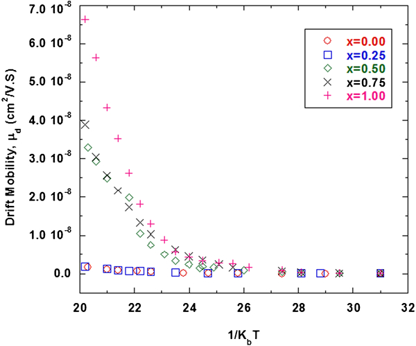
Effect of temperature on drift mobility μd in prepared nanoferrites of Mn1−xNixFe2O4 for various Ni concentrations of x = 0·00, 0·25, 0·50, 0·75 and 1·00
Dielectric characteristics
In the current work, the dielectric characteristics of the prepared ferrites of Mn1−xNixFe2O4 with varying applied frequency f and Ni concentrations x = 0·00, 0·25, 0·50, 0·75 and 1·00 have been investigated. The results are summarised in Table 1 and discussed below.
Dielectric constant ϵ′
The dielectric behaviour of ferrites is one of the most important characteristics of the type of electrical insulator that may be polarised in the presence of an applied electric field. Under such condition, electric charges slightly shift from their average equilibrium positions to induce dielectric polarisation rather than flow through the material as in the case of a conductor. Considering this, the term ‘insulator’ refers to the electrical conduction of a low degree, while the term ‘dielectric’ is generally used to describe the behaviour of the material with a high polarisability expressed by a number called the dielectric constant ϵ′. In the current work, dielectric constant ϵ′ measurements were carried out in the frequency range from 0·1 to 5·0 MHz at room temperature, i.e. 373 K. The dielectric constant values ϵ′ have been obtained from the standard relation given in equation (4), and the results obtained are summarised in Table 1 and presented in Fig. 5.
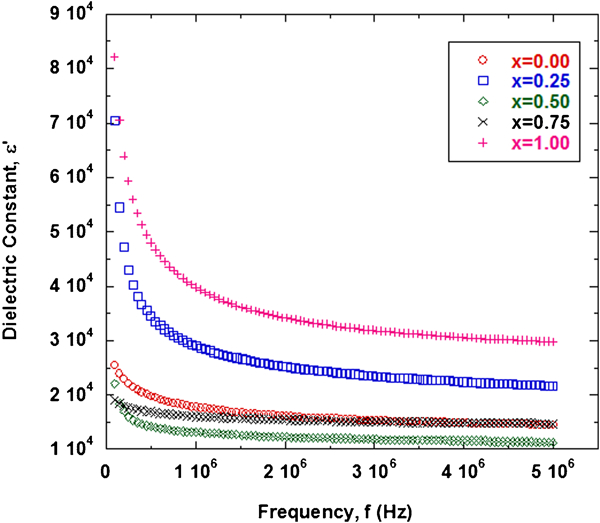
Effect of frequency on dielectric constant ϵ′ for various Ni concentrations in prepared nanoferrites of Mn1−xNixFe2O4 (x = 0·00, 0·25, 0·50, 0·75 and 1·00)
Figure 5 indicates several interesting observations to represent the dielectric dispersion in ferrites. It is evident that the values of ϵ′ are much higher at lower frequencies. Further, the ϵ′ values continue to decrease with the increase in frequency and decreased steeply at lower frequency, while at high frequencies, their values become smaller, exhibiting an independent behaviour for all the compositions investigated. These observations are in good agreement with the usual dielectric behaviour of ferrites and suggest complex contributions of compositional, structural and morphological factors. The dispersion in frequency dependence of ϵ′ can be explained on the basis of the Maxwell–Wagner interfacial type polarisation,29 which is in agreement with Koop's phenomenological theory.30 According to this theory, the conductivity of grain boundaries is higher at lower frequencies to contribute more towards the dielectric value due to the predominance of species such as Fe2+ ions, vacancies, grain boundary and interfacial dislocation pile-ups.29 The decrease in ϵ′ values with the increase in frequency for the prepared nanoferrites is observed because any species contributing to polarisability seem to lag behind the applied field at higher frequencies.31 On the other hand, in the lower frequency regimen, there is dispersion in ϵ′ values due to interfacial polarisation as electronic and atomic polarisations remain approximately constant at such applied frequencies. Furthermore, the dielectric polarisation in ferrites is similar with the conduction hopping mechanism.23,
24 Hopping between Fe2+ and Fe3+ produces the local displacement of electrons in the direction of the applied field, and these electrons then determine the polarisation. It is greatly influenced by the frequency as well as the structural arrangements in the spinel ferrites, such as the electron exchange between Fe2+
 Fe3+ ions in between tetrahedral and octahedral sites. This variation in the concentration of Fe2+ ions results in local displacement of electrons in the direction of the electric field to influence electric polarisation in spinel ferrites, and hence, both polarisation and ϵ′ are expected to increase with the concentration of Fe2+. As the applied frequency increases, polarisation decreases and then reaches a constant value because; beyond certain higher frequencies of the external field, the electron exchange between Fe2+
 Fe3+ cannot follow the alternating field, and thus, it exhibits the approximately constant values of ϵ′.32
Dielectric loss factor tan δ
The dielectric loss factor or tangent loss factor tan δ as a function of frequency was studied at room temperature, i.e. 373 K. The tan δ values were obtained from the standard relation given in equation (5). Figure 6 represents the variation of tan δ at room temperature as a function of applied field frequency. It is evident that, for each composition, tan δ values are found to decrease with an increase in applied frequency. All the samples exhibit dispersion due to the Maxwell–Wagner interfacial type polarisation, in agreement with Koop's phenomenological theory, as discussed above.30 The decrease in tan δ takes place when the jumping rate of charge carriers lags behind the alternating electric field beyond a certain critical frequency. The change in tan δ is greater at low frequencies and smaller at high frequencies for the investigated samples. There is a strong correlation between the dielectric behaviour and the conduction mechanism in ferrites. As discussed earlier, conduction in ferrites is considered to be due to the hopping of electron between Fe ions in different valence states +2 and +3 over the octahedral sites. From these considerations, one can see that the behaviour of tan δ with frequency is showing the expected decrease in its value with the increase in the applied frequency. Similarly, the dielectric loss ϵ‘’ values were calculated from the relation ϵ″ = ϵ′tan δ. The dielectric loss of the prepared nanoferrites was observed to follow the typical ferrites’ behaviour and was found to decrease with the applied frequency, as presented in Fig. 7. Dielectric loss is an important part of the total core loss in ferrites, and therefore, low dielectric losses and electric polarisation are highly desirable.33 The dielectric loss increases with the increment of local displacement of hopping of electrons in the direction of the applied electric field and generally reflected in the conductivity measurements as the materials with high losses also exhibit high conductivity and vice versa.
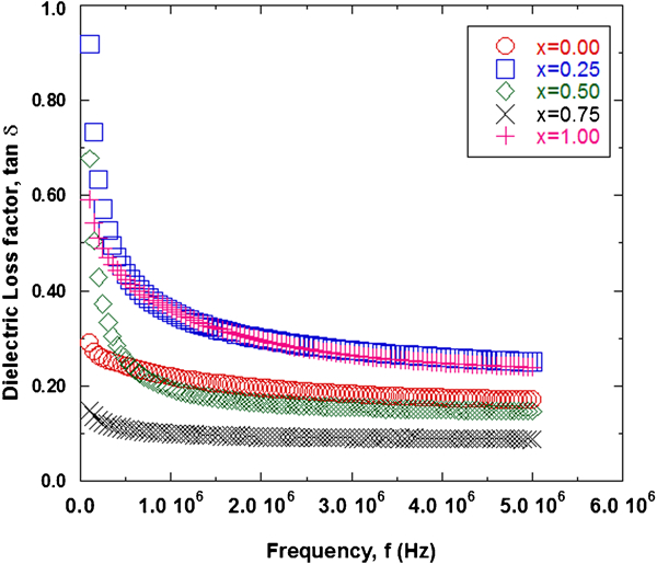
Effect of frequency on dielectric loss factor tan δ for various Ni concentrations in prepared nanoferrites of Mn1−xNixFe2O4 (x = 0·00, 0·25, 0·50, 0·75 and 1·00)
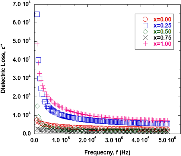
Effect of frequency on dielectric loss ϵ′′ for various Ni concentrations x = 0·00, 0·25, 0·50, 0·75 and 1·00 in prepared nanoferrites of Mn1−xNixFe2O4
Alternating current conductivity σac
To understand the conduction mechanism in the prepared nanoferrites of Mn1−xNixFe2O4, the ac conductivity σac was also studied as a function of frequency f. Figure 8 shows the variation in σac versus ln f. The plots are approximately linear to indicate that the σac values increase with the increase in frequency and thus exhibit a similar trend as other ferrites do.34 The observed results again can be explained by considering the electrical conduction mechanism in terms of the electron and polaron hopping model. In the current work, the plots are approximately linear, suggesting conduction with a small polaron type as it is known to be valid for ionic solids. With the increase in applied frequency hopping, conduction also increases to induce a gradual increase in conductivity since there are more electron hopping between two adjacent octahedral sites (B sites) and transition between Fe2+ and Fe3+ ions in the lattice structure. As discussed earlier, the frequency dependent conduction is mainly attributed to a small polaron type hopping mechanism, and the present study also supports that, because of the linear response of σac to the frequency, the conduction mechanism in the nanoparticles of Mn1−xNixFe2O4 spinel ferrite is of a small polaron type.
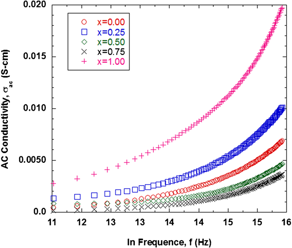
Effect of frequency on ac conductivity for various Ni concentrations x = 0·00, 0·25, 0·50, 0·75 and 1·00 in prepared nanoferrites of Mn1−xNixFe2O4
Conclusion
It can be concluded that the substitution of Ni in Mn1−xNixFe2O4 (x = 0·00, 0·25, 0·50, 0·75 and 1·00) spinel ferrites produced significant changes in their electrical and dielectric properties. The dc electrical resistivity ρdc of the prepared nanoferrites with sizes between 13 and 25 nm was measured, and other electrical parameters such as activation energy ΔE and drift mobility μd were also obtained. The dc electrical resistivity was measured in the temperature range of 373–573 K and was found to increase with the increase in the concentration of Mn in the ferrites. This observation is attributed to the hoping conduction mechanism model of electron and polarisation. In addition, the dc electrical resistivity was found to decrease with the increase in temperature and follow the Arrhenius relation observed normally in ferrites to confirm the semiconductor characteristics of the prepared nanoferrites. Activation energy ΔE and drift mobility μd of the prepared nanoferrites were found to decrease with the increase in Ni concentration x. The drift mobility exhibited linear dependence on temperature, while the activation energy showed an inverse dependence on resistivity. The decrease in dielectric constant ϵ‘ and loss tangent tan δ with frequency in the range of 1–5 MHz shows dielectric dispersion in the lower frequency region. The ac conductivity of the samples observed to increase with an increase in applied frequency supports the conduction mechanism of small polaron hopping type.
The study of the electrical and dielectric properties of the prepared Mn1−xNixFe2O4 spinel nanoferrites has important prospective applications for various electronic devices. The results obtained indicate that, with an increase in the Ni ion concentration, electrical properties can be tuned to control the electrical resistivity of the synthesised ferrites and thus have important practical applications. For example, an increase in the Ni ion concentration results in the enhancement of the conductivity and is therefore capable to cause a decrease in the electric power losses in various electronic circuitries in devices such as those of computers and transformer coils. On the other hand, however, this factor can affect the capability of charge storage in the capacitors. This is because the materials with a small Ni extent can possess higher polarization density and the capacitor would polarize in short amount of time. Therefore, the higher conducting ferrite materials with more Ni contents can cause degradation of the charge storing capabilities of capacitors, but higher contents of Mn in a capacitor can result in an improvement in its charge storing capabilities.
Footnotes
Acknowledgements
The authors thank Z. Iqbal, S. Ameer, N. Ahmed, S. Ahmed and A. Ahmed from the School of Chemical and Materials Engineering, National University of Sciences and Technology, for their support in carrying out the characterisation of the samples.