
Abstract
Laser cladded coatings have been used extensively to extend the service life of components exposed to severe abrasive wear. One of the main wear resistant materials used in laser cladding is ceramic–metallic composite. Despite extensive use of this class of material, there is very limited knowledge regarding mechanical degradation mechanisms, such as cracking and plastic deformation, under different wear conditions. In this investigation a mixture of nickel alloy and tungsten carbide powders were used to deposit the coating. Two types of tungsten carbide powders with spherical and angular carbides were employed. The microstructures of the coatings were analysed thoroughly by optical microscopy, electron probe microanalysis and wavelength dispersive spectrometry. Failure and cracking mechanisms of laser cladded coatings under normal and tangential loading were systematically investigated using scratch testing. In the nickel alloy matrix, fine mixed secondary carbides were formed due to partial dissolution and formation of the secondary tungsten carbide during laser cladding. These secondary carbides were rich in chromium, tungsten and nickel and had a blocky and/or bar-like shape. Failure mechanisms associated with scratch testing were dependent on the microstructure and carbide morphology, applied stress and location of carbide particles with regard to the scratch groove. Owing to the high binder mean free path between the carbide particles, plastic deformation of the binder was the dominant failure mechanism. Additionally, partial or whole fragmentation of carbides, carbide/binder interface cracking and limited binder fracture were observed.
Introduction
During laser cladding, a coating is formed by partially melting of additive materials in the form of wire or powder by a laser beam as energy source. Laser cladding is characterised by minimal dilution between substrate and deposit that results in a strong metallurgical bond between the substrate and the coating. The rapid solidification during laser cladding results in coatings with a very fine microstructure comprising of phases formed in non-equilibrium conditions. Additionally, the rapid cooling allows the production of ceramic reinforced metal matrix composite (MMC) coatings with minimal dissolution of the ceramic phase in the metallic matrix. In MMCs, the ceramic particles provide hardness and the matrix provides toughness. The main parameters influencing the abrasive wear mechanism of ceramic reinforced metal composites are the contact stress, the reinforcement grain size, grain type, volume fraction of hard particles and the binder, binder mean free path (which is defined by volume fraction and particle size) and size and type of abrasive particles.1–4
It is known that the microstructural features and properties of laser cladded coatings depend on the characteristics of the feedstock powder and the process parameters. Process parameters in laser cladding are laser power, scan speed, preheating temperature, laser wavelength, shielding gas and powder flowrate. As reported by Hutchings5 and Gahr,6 the wear behaviour of MMC materials depends first on the relation between the size of the reinforcement particles and the dimensions of the damage caused by the abrasive. If the scale of the damage is similar or smaller than the scale of the reinforcement particles, the matrix and the reinforcement will respond individually. In MMCs, different wear mechanisms have been identified such as plastic grooving, binder phase extrusion and removal, fracture and detachment of reinforcing particles, Palmqvist cracking and subsequent spalling, and detachment of materials.1–3,7–9
The resistance of a material to abrasive wear is usually studied by multiple asperity wear where the material is worn against some form of standard abrasive medium such as abrasive paper. These experiments provide quantitative data useful for practical applications and enable ranking different material systems based on their wear resistance at particular test conditions. However, these tests reveal only little about their underlying basic wear mechanisms. Scratch test experiments provide useful information on the mechanisms of wear based on the response of a material to a single abrading particle (sliding tip) with the known geometry and the known contact load.10 Scratch testing of metal–ceramic composites has been performed by other authors in order to understand their behaviour during abrasive contact.10–14
Microstructure and tribological characteristics of laser cladded coatings composed of a nickel alloy matrix reinforced with tungsten carbide particles have been studied.8,15–21 Previous work about microstructural features and high temperature sliding wear resistance of these coatings can be found in Ref. 21. However, there is very limited understanding of the fundamental influence of microstructural parameters on wear behaviour, especially of the effect of the shape of reinforced particles.
The laser cladded coatings studied in this paper consist of a nickel alloy binder reinforced with two types of tungsten carbide particles with considerable different aspect ratios. This study aims at gaining a fundamental understanding of the wear mechanisms of such laser cladded MMC coatings during sliding contact at various contact loads and with two different WC aspect ratios (spherical and angular carbides) by performing controlled scratch test experiments.
Experimental
Two types of coatings were produced using mixtures of nickel alloy powder with angular and spherical fused tungsten carbides by laser cladding. The composition of the nickel based alloy is Ni–7·5Cr–1·6B–3·5Si–0·3C–2·6Fe (wt-%). The particle size of the carbides is in both cases between 45 and 125 μm. The powder mixtures consist of 40 wt-%Ni alloy and 60 wt-% tungsten carbide powders.
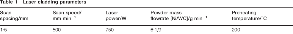
Laser cladding experiments were performed with a fibre coupled 3 kW Laserline diode laser and coaxial cladding nozzle. The laser spot diameter at the substrate was 3·75 mm. Argon gas was used as transport gas for the powder and as shielding gas in the coaxial cladding nozzle. The process parameters are shown in Table 1. The coatings were processed on 6 mm thick steel substrates.
Laser cladding parameters
Electron probe microanalysis (EPMA) using wavelength dispersive spectrometry (WDS) was used to analyse the phase constitution of the coatings. The overall hardness of the coating was measured on the cross-section of the coating by Vickers hardness testing using a 1 kg load. The hardness and elastic modulus of the metallic matrix and the tungsten carbide reinforcing phase in the coating was measured using instrumented Vickers microindentation with 0·3 kg load.
Scratch tests were performed employing a conical diamond stylus with tip diameter of 400 μm and tip angle of 120°. The applied normal load was continuously increased from 5 to 50 N along a scratch length of 10 mm. The generated scratch grooves were studied by optical microscopy to address the overall failure mechanisms.
Results and discussion
Coating characterisation
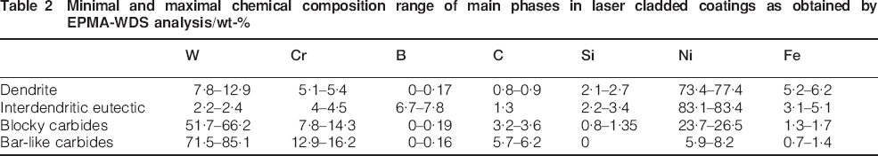
Figure 1a and b shows the optical micrographs of the coatings containing spherical and angular tungsten carbides respectively. The darker discrete phase corresponds to the carbide particles. The coatings are dense except from the presence of some spherical pores in the metallic matrix and in some spherical carbides. No cracks are present in the coatings. Figures 2a to 2d depict the EPMA images of the coatings containing spherical and angular tungsten carbides. In the matrix of both coatings, two nickel rich phases are present. A dendritic Ni based phase forms first during solidification (see Table 2). Between the dendrites, a lower melting point eutectic phase with relatively high boron and carbon content is formed afterwards, as detected by EPMA-WDS analysis (see Table 2). The morphology of carbide powder does not affect significantly the chemical composition of the nickel rich phases in the laser cladded coatings.
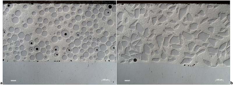
Optical micrographs of cross-section of laser cladded coatings composed of nickel alloy matrix and 60 wt-% a spherical and b angular tungsten carbide reinforcement
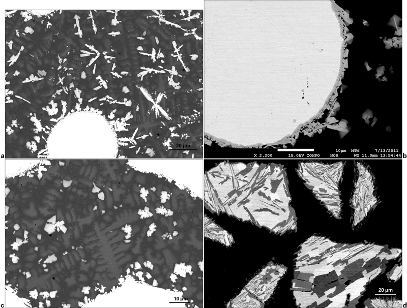
Electron probe microanalysis micrographs of laser cladded coatings composed of nickel alloy matrix and 60 wt-% a, b spherical and c, d angular tungsten carbide reinforcement
Minimal and maximal chemical composition range of main phases in laser cladded coatings as obtained by EPMA-WDS analysis/wt-%
Material characteristics of the laser cladded coatings are presented in Table 3. The W2C/WC ratio was obtained from X-ray diffraction intensity peak values.
Material characteristics of laser cladded coatings
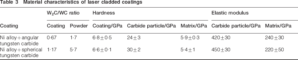
In the angular tungsten carbide, particles that formed different carbide phases corresponding to WC and W2C were identified. Similar types of carbides were also identified by X-ray diffraction in the feedstock powder. The structure in the spherical fused carbide powder is finer than in the angular fused carbide powder due to the higher cooling rate during the fabrication process of spherical fused tungsten carbide powder. The ratio of W2C to WC phase in the coatings is lower than in the feedstock carbide powder (see Table 3). This can be attributed to the preferential dissolution of the W2C phase compared to the WC phase.
In the angular carbides, protrusions can be observed at the outer edge of the particles (Fig. 2d). The protruding areas are always WC crystals (dark colour), which have been left behind due to accelerated dissolution of the W2C phase. At the edge of the spherical particles, a mixed carbide phase is formed (light grey phase in Fig. 2b), which is of the type MC with M = W, Ni as revealed by WDS analysis. Some dissolution of the carbides at their edges is beneficial as it improves the bonding between the ceramic phase and the matrix.
Secondary carbides, which are formed by reaction between the tungsten carbide particles and the Ni alloy during laser cladding, are revealed in the matrix of both coatings (see Fig. 2a and c). This is also confirmed by X-ray diffraction.21 The secondary carbides in the coatings with angular carbides have primarily a block shape, while in the presence of spherical tungsten carbides, a significant amount of bar-like carbides are formed in addition. Electron probe microanalysis analysis indicates that the blocky carbides are rich in W, Cr and Ni (see Table 2). The bar-like carbides contain a lower amount of Ni and higher amount of Cr and W.
In Table 3, the hardness and elastic modulus of the primary tungsten carbide phase and of the matrix are presented. The hardness and elastic modulus of an individual spherical carbide particle are higher than that of angular carbide particles. Higher hardness values for spherical carbide particles are attributed to a higher percentage of the harder and more brittle W2C phase as well as a finer microstructure.
Scratch testing
The crack patterns observed on the carbide particles are schematically presented in Fig. 3 for coatings containing spherical carbides and in Fig. 4 for coatings containing angular carbides. The actual optical images of each pattern, which are shown schematically in Figs. 3 and 4, are shown in Figs. 5 and 6 respectively.
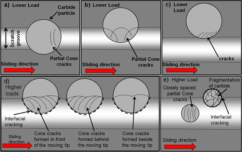
Schematic of failure mechanisms during scratch testing at low and high loads of laser cladded coatings composed of nickel alloy matrix and spherical tungsten carbide reinforcement
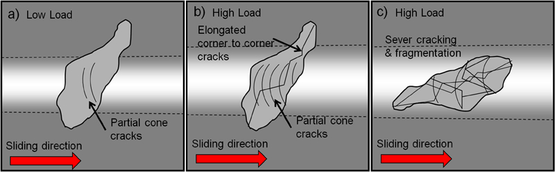
Schematic of failure mechanisms during scratch testing of laser cladded coatings composed of nickel alloy matrix and angular tungsten carbide reinforcement
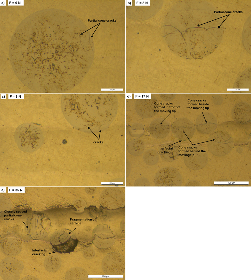
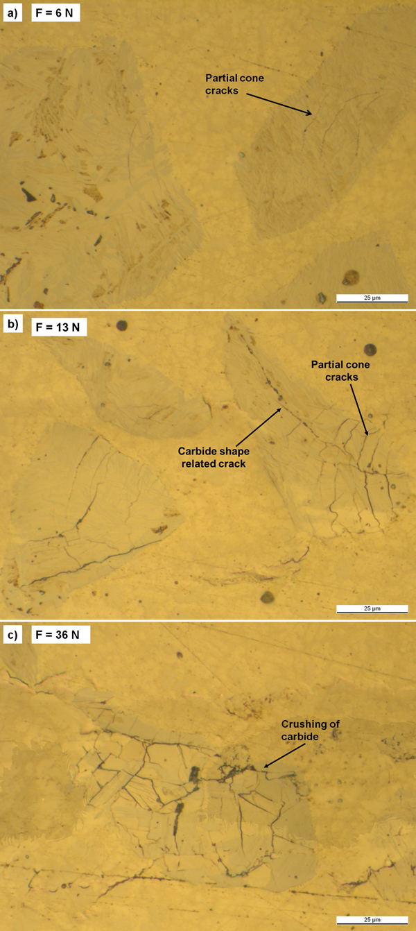
Optical images of failures in laser cladded coatings composed of nickel alloy matrix and spherical tungsten carbide reinforcement corresponding to failure modes in Fig. 3 (sliding direction of tip countersurface is shown by arrows)
Optical images of failure mechanisms in laser cladded coatings composed of nickel alloy matrix and angular tungsten carbide reinforcement corresponding to failure modes in Fig. 4 (sliding direction of tip countersurface is shown by arrows)
Spherical carbide particles’ crack patterns
In analysing the scratch tracks, the location of the carbide particles with regard to the scratch groove and the loading magnitude is important. It should be noted that scratch testing is performed using a sliding tip that has a higher hardness than the metallic binder and the reinforcement particles.
Figure 3a–c depicts the cracking patterns schematically at lower loads, and Fig. 5a–c depicts the actual optical images of cracking patterns. In case of low normal loads, the width of the scratch groove is smaller than the carbide particle size.
For carbides located in the middle of the scratch groove, very small partial cone cracks, within the carbide particle close to the edge of particles, were observed (Figs. 3a and 5a). The cracks are formed at the trail of the moving diamond tip. This is indicated by the shape of the semicircular partial cone cracks.22–24 When a carbide particle is covering the entire width of the scratch groove, the load is primarily carried by carbide phase. In sliding contact mode, tangential friction forces result in high tensile stresses and consequent failure by cracking at the trail of the sliding tip. A similar observation is reported in scratching of titanium carbide reinforced MMCs.14
When the carbide particle is partially in contact with the moving tip, multiple cone cracks, which tend to form a ring around the contact area, are observed on the surface of the carbide particle (Figs. 3b and 5b). When the edge of the carbide particle is located at the edge of the scratch groove, fine and small cracks are observed within the carbide, originating from the edge of the carbide particle and propagating towards the centre of the particle (Figs. 3c and 5c).
Figure 3d and e depicts the cracking patterns schematically at higher loads, and Fig. 5d and e depicts the actual optical images of cracking patterns. In case of higher normal loads, the width of the scratch groove is the same or bigger than the carbide particle size.
More closely spaced cone cracks were observed on the surface of the carbide particles. These partial cracks were observed behind, in front or beside the moving tip (Fig. 3d) depending on the location of particles regarding to scratch groove. Crack formation in front of the moving tip requires high loading, as tensile stresses in front of the moving tip are smaller than those formed at the trail of the moving tip during scratch testing.25
Interfacial cracking between the carbide particles and the metallic binder was observed at high loading conditions. Cracking at the interface is hypothesised to be due to formation of peak stresses at the interface. The formation of high stresses at the interface might be caused by the difference in elastoplastic response of the carbide and the metallic matrix to deformation under the sliding tip. At the highest loadings where the scratch groove is wider than the carbide size, complete fragmentation of carbide particles located either at the centre or at the edge of the groove under the harder tip was observed (Fig. 3e).
Angular carbide particles’ related crack patterns
If the aspect ratio of the angular carbides is close to 1, the cracking patterns observed on carbide particles are similar to those for spherical carbides. In the following, the cracking patterns on the surface of angular carbide particles with an aspect ratio of smaller than 0·25 are discussed.
Similar to the spherical carbides, in case of angular carbides, the location of carbide particles relative to the scratch groove and the load range are two crucial factors in defining the cracking patterns.
Figure 4a and b shows low and high load situations. In case that the width of the scratch groove is smaller than the carbide particles and the sliding tip passes through the middle of the carbide (Fig. 4a), very small semicircular cone cracks within the carbide particle close to the edge of particle were observed. The cracks are formed at the edge of particles where the moving tip leaves the carbide particle. This observation is similar to the coatings with spherical carbides (Fig. 3a). At higher loads, more and closely spaced partial cone cracks were observed. Additionally, longer cracks propagating from one edge to another edge of the particle were formed (Fig. 4b). Latter cracks (corner to corner cracks) were not observed in spherical carbide particles. This is attributed to the higher stress concentrations at sharp edges. At higher loads, if the orientation of the carbide is in such a way that the entire particle is located within the scratch groove, complete fragmentation of the carbide under the hard diamond tip will occur (Fig. 4c).
Damage mechanisms related to matrix
The dominant failure mechanism observed in the matrix was related to plastic deformation due to the high binder mean free path between the carbide particles. Plastic deformation at very low loads was observed as a scratch groove and at higher loads as a deeper scratch groove with pile-up of material around the groove. Figure 7 shows the smearing of metallic binder over the carbide particle that is an evidence of extensive plastic deformation of binder. In addition to plastic deformation, some limited cracking in the matrix was observed at the edge of the scratch groove for coatings with spherical carbides. This type of cracking was more pronounced for coatings containing angular carbides. This might be addressed by recourse to the higher hardness and elastic modulus values for the matrix in the presence of angular carbide reinforcements (Fig. 5e).
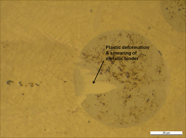
Extensive plastic deformation and smearing of metallic matrix over carbide particle
Conclusion
Laser cladded coatings composed of a nickel alloy matrix and large sized spherical or angular fused tungsten carbide reinforcements were analysed in terms of microstructural features and mechanical properties. The following can be concluded.
The analysis showed that the matrix consisted of Ni rich phases and fine carbides rich in Cr, W and Ni. The overall coating hardness of the two coatings was about the same. However, hardness and elastic modulus of spherical carbides were higher compared to angular carbides. Hardness and elastic modulus of coating with spherical carbide showed lower values compared to binder of coating with angular carbides. At the carbide/matrix interface, dissolution of the tungsten carbide resulted in the formation of secondary carbides.
Controlled scratch testing of the two coatings resulted in a regular and repeatable cracking pattern as a result of the stresses, strains and deformations, on both macro- and microscale, in and around the scratch groove. The magnitude of loading and the aspect ratio of the carbides had a significant influence on the cracking pattern.
At low loadings for coatings with spherical or angular carbides, semicircular partial cone cracks were formed behind the sliding tip for carbides located in the middle and at the edge of the scratch groove. These were formed as a result of tangential friction forces and surface bending during sliding contact.
At high loadings, more semicircular cracks originate behind but also in front or aside the moving tip. Cracks at the edge of the particles and parallel to the sliding direction were formed. This is attributed to material pile-up at the edges of the groove, which causes high tensile stresses perpendicular to the scratch track. In addition, interfacial cracking between the spherical carbides and the matrix was observed.
For angular carbides, similar failure mechanisms were observed, but in addition, large cracks that propagated from corner to corner of the particle were present due to high stress concentrations at sharp edges. More extensive cracking in the matrix was observed. However, there was no interfacial cracking.
The dominant failure mechanism in the binder was plastic deformation. Additionally, limited cracking at the edge of the scratch groove for coatings with spherical particles was observed. Cracking at the edge of the scratch groove within the binder was more pronounced for coatings with angular carbides.
Footnotes
Acknowledgements
AG would like to thank Mr A. Thompson Mr. Kenneth Krienke (The Boeing Co.) for their valuable comments. This study was carried out in the Matera project MOTRICOT (Model based tribologically optimised thick multimaterial coated surfaces). The financial supports of Consortium for Thermal Spray Technology (Stony Brook University), Tekes (the Finnish Funding Agency for Technology and Innovation); The Institute for the Promotion of Innovation by Science and Technology of Flanders (IWT); the participating industrial companies Metso and Ruukki; and the VTT Technical Research Centre of Finland are gratefully acknowledged.