
Abstract
A melt urea pump is out of work after only 6 days in service. The failure of the melt urea pump impeller is analysed using different methods including chemical composition analysis, metallographic observation, SEM and energy dispersive spectroscopy analyses, etc. The results show that the material of the impeller is not the reported AISI 321 stainless steel but AISI 316 stainless steel. There are many honeycombed holes on its impeller, which is the typical feature of cavitation damage. Therefore, the main failure reason of the impeller is the cavitation erosion, and the electrochemical corrosion of the medium also accelerated the failure of the impeller. The failure of the impeller is not related with the as casted defects of the material because no obvious as casted defects are found in the material.
Introduction
A melt urea pump is a kind of centrifugal pump. It is often used to transport the melt urea in fertilizer plants. The diagram of a centrifugal pump is shown in Fig. 1. The impeller, pump shell and pump shaft are the three key components of a centrifugal pump. The former two components are the flow handling parts.
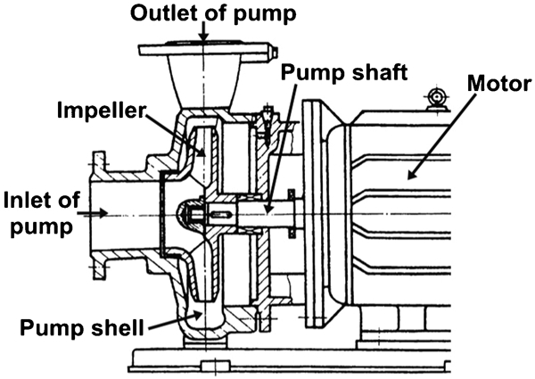
Profiles of centrifugal pump
Melt urea pump failures can be attributed to many reasons. Failure often causes accidents and economic losses. Owing to the complex and asymmetric geometry of the impeller and volute, the relative motion between impeller and volute leads to a complex flow regime involving turbulence, unsteadiness, secondary flows, etc. 1 The pressure fluctuations of the flow can easily cause the occurrence of cavitation, which may result in the damage of the impeller and pump shell. Moreover, the slurry erosion of the impeller and pump shell can also accelerate the pump failure when the pump transports liquid particle two-phase flows containing great quantities of mud and sand. Fretting wear between the impeller and shaft is another aspect resulting in the pump failure. In addition to these mechanical aspects of damage, the electrochemical corrosion to the flow handling components in the pump also threatens the integrity of the pump, especially in the chemical industry. The fluid transported by the pump often contains corrosive substances.
In a fertilising plant, a melt urea pump failed due to the perforation of the impeller after working for only 6 days. It was necessary to figure out the reasons causing the premature failure in such a short time, and this paper addresses some of the issues. The working conditions of the failed impeller are listed in Table 1.
Working conditions of failed impeller
Failure analysis
Visual examination
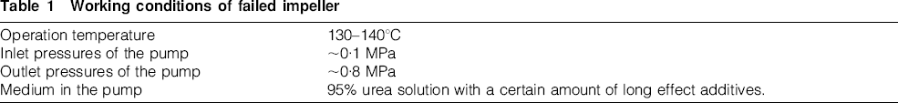
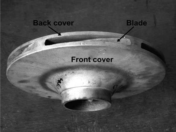
The failed impeller is an enclosed impeller with a diameter of 250 mm. Figure 2 shows that the impeller is composed of blades, front cover and back cover. The impeller has six flow channels. Three of them have big inlets (marked as 1, 3 and 5 in Fig. 3), and the other three have small inlets (marked as 2, 4 and 6 in Fig. 3). The big and small channels are in alternative distribution (Fig. 3b). Most damaged areas are right along the flow directions of the small flow channels, which are shown in Fig. 3a, c and e. Figure 3c and e are the magnified graphs of the damaged areas in Fig. 3a. There are many holes in the particular area of the impeller's front cover and blades. The holes penetrate the front cover and the blade to the side of the big channel (Fig. 3d). From Fig. 3f, it is noticed that the damage is very serious at the joint position between the front cover and the blade of the small channel's side.
Failed impeller
Damaged areas of impeller: a, c, e the most damaged areas of the front cover; b, d, f the most damaged areas in the channels (1, 3, 5 the big channels; 2, 4, 6 the small channels)
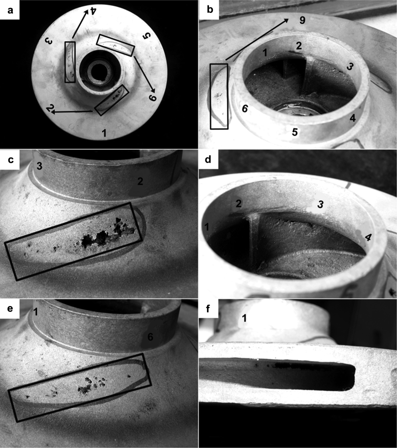
To further clarify the damage features, the failed impeller was cut into pieces, and the cutting directions (white dotted lines) are shown in Fig. 4a. Local magnifications of the damage regions are presented in Fig. 4b–d. It is clear to observe that the damages concentrate at the joints between the front cover and the blades. Figure 4e shows one of the typical damaged areas of the impeller; the damaged area was cut into two parts along the white dotted line. The macrofeatures of the parts 1 and 2 are displayed in Fig. 4f–h. It is obvious that the damage has honeycombed pattern and indicates that the perforation initials from the side of channel 2 (small channel) and penetrates the blade and the front cover.
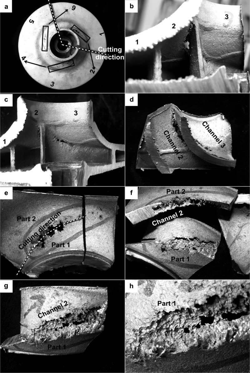
Macrofeatures of typical damaged areas: a cutting directions of the impeller; b, c, d the local magnifications of the damaged areas; e one typical damaged area and its cutting direction; f, g the macrofeatures of part 1 and 2; h the local magnifications of g
Figure 5 indicates the stereoscopic view of typical damaged areas for different positions. Figure 5a–d shows the small holes on the slight damaged areas of the blade and the front cover. It illustrates that the holes are perpendicular to the metal surface. For Fig. 5e–i, the most damaged areas on the front cover are shown, which have a typical honeycombed pattern and break through the whole front cover.
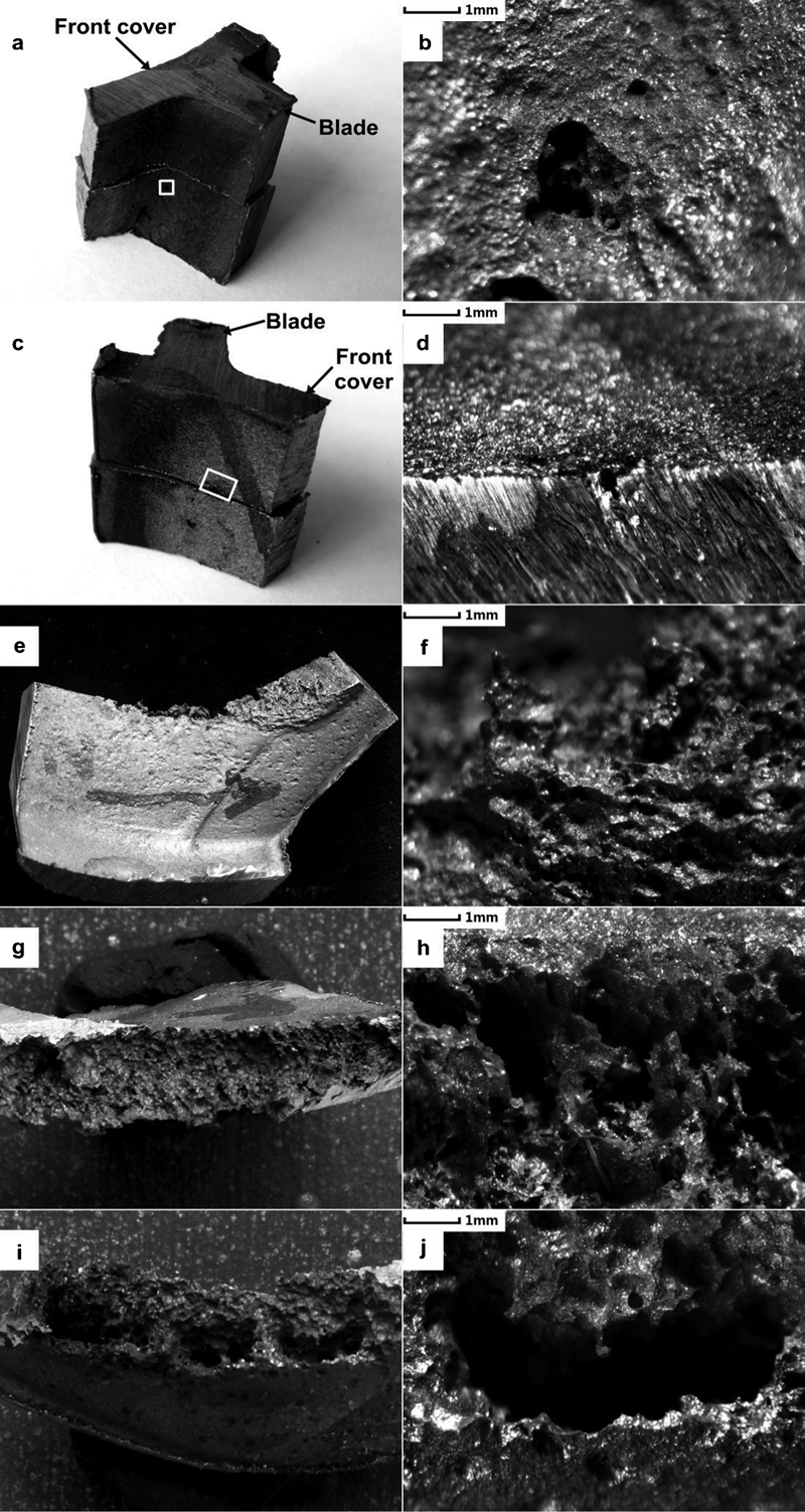
b, d, f, h, j stereoscopic view of typical damaged areas for different positions (a blade; c front cover; e, g and i most damaged front cover)
It is known that cavitation is defined as the formation and then immediate implosion of cavities in a liquid. It usually occurs when a liquid is subjected to rapid changes of pressure that cause the formation of cavities where the pressure is relatively low. Cavitation erosion is the mechanical degradation of the material and has often been found in flow handling parts of equipment, such as pumps, valves, pipelines, hydroturbines, etc. Cavitation erosion of materials has the following distinguishing features in general: 2
the damaged position has a honeycombed pattern 3
most of the holes are perpendicular to the metal surface
the honeycombed holes are connected with the outside in ordinary circumstances.
Therefore, the macrofeatures of the damaged impeller have typical characteristics of cavitation erosion.
Chemical composition analysis
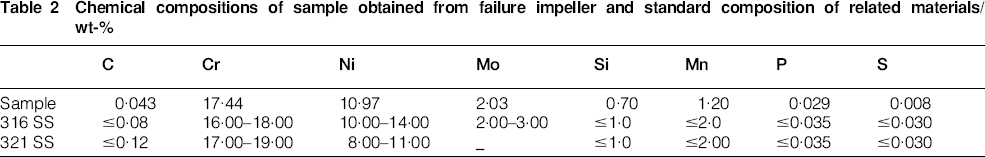
Fluorescence Spectrometry was utilised to analyse the chemical composition of the sample taken from the impeller. Comparison was performed with the standard chemical composition of AISI 316 (316 SS) and AISI 321 stainless steels (321 SS). The results are listed in Table 2. It can be observed that the chemical composition of the sample is in accordance with that of the 316 SS. Therefore, the sample material is not the 321 SS as reported.
Chemical compositions of sample obtained from failure impeller and standard composition of related materials/wt-%
Metallographic observation
Some defects may exist in cast materials and cause a lot of failures. Therefore, different samples are taken from three typical regions and examined by a metallographic microscope to identify their effects on the failure of the impeller. As shown in Fig. 6, sample 1 is located on the edge of impeller where materials solidified earliest and where the least defects exist. In contrast, samples 2 and 3 are near the casting head of the impeller where materials solidified latest and have the largest defects. In general, sample 2 is in the same radial direction as sample 1; samples 2 and 3 locate at the same circumference. All the samples are polished and electrolytic etched by 10% oxalic acid solution.
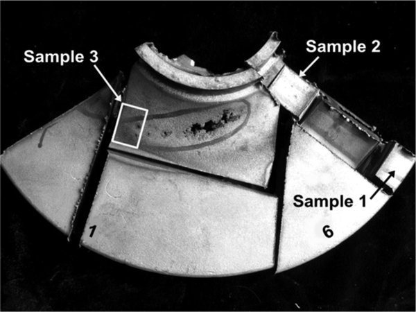
Metallographic samples obtained from different positions of impeller
Figure 7 presents the metallographic structures of the three samples. Samples 1 and 2 have similar microstructure, which is consisted of austenite and dendritic δ-ferrite. There is no obvious casting defect in the samples 1 and 2. However, selective corrosion of ferrite occurs on the surface of the samples due to the etching (Fig. 7a and c). Moreover, sample 3 shows a great number of holes on the base metal with the selective corrosion of ferrite phase. However, the microstructure of the rest part of base metal is similar with samples 1 and 2. These illustrate that the failure of the material does not relate to the casting defects. Therefore, through the metallographic observation of the three typical areas of the impeller, no obvious casting defects are observed at the failure part of the impeller; it means that the casting defects seem to play no significant role in the failure of the impeller.
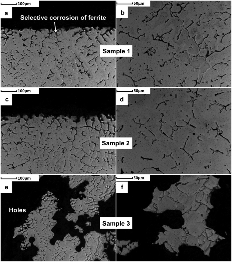
Microstructures of different samples: a, b sample 1; c, d sample 2; e, f sample 3
Scanning electron microscopy (SEM) and energy dispersive spectroscopy (EDS) analyses
Figure 8 shows the SEM images of the typical holes of the impeller and the EDS detection sites of the samples. Energy dispersive spectroscopy analysis shows that chemical composition of the damaged area are mainly composed of C, O, Cr, Fe, Ni, S, Al and Si elements. Cr, Fe and Ni are the elements of the impeller materials, and the other elements must come from the environments. It is worthwhile to notice that the damaged areas have high sulphur content. This must be related with the additives added to the medium, which are normally dicyandiamide and sulphocarbamide in the urea industry.
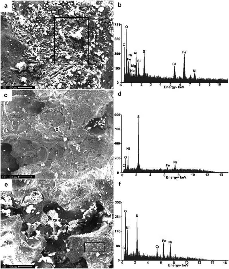
Morphologies (SEM) and EDS results of adhering products a, b on metal surface, c, d near the holes and e, f on base metal near holes
Discussion
As mentioned in the section on ‘Visual examination’, the macrofeatures of the damaged impeller have typical characteristics of the cavitation erosion. Therefore, cavitation erosion must be one of the main reasons causing the failure of the impeller.
Cavitation effect on failure
The circumferential pressure distribution in the pump is presented in Fig. 9. More details can be referred to Cheah's paper. 4 The liquid pressure increases along the inlet of the pump to the inlet of the impeller, while the centrifugal pump is working and drops to the bottom Pk at the point near the inlet of the impeller. Then, it increases quickly due to the work of the impeller to the liquid. If Pk is lower than the saturated vapour pressures Pv of solution at the temperature of pumping liquid, the liquid will vaporise. Meanwhile, the gas dissolved in the liquid will escape and form bubbles. When the bubbles flow into the channels with the liquid flow, the external component pressure of liquid is higher than that in the bubbles. Therefore, they collapse in extremely short time and form cavities. Then, the surrounding liquid rushes into the cavities at a tremendous speed and makes the local pressure increasing rapidly (even up to hundred times of atmospheric pressure). 5 If these bubbles collapse near the wall surface of the impeller, the surrounding liquid will impinge against the wall repeatedly and forcefully just like numerous microbullets, which is strong enough to cause local fatigue of the wall material. The frequency of the impingement is approximately up to 2000–3000 Hz. At the weakest part of the metal surface, the pits due to the grains’ peeling off will cause stress concentration, which will further accelerate the peeling off. The impeller will be deteriorated and result in the honeycombed morphology finally.
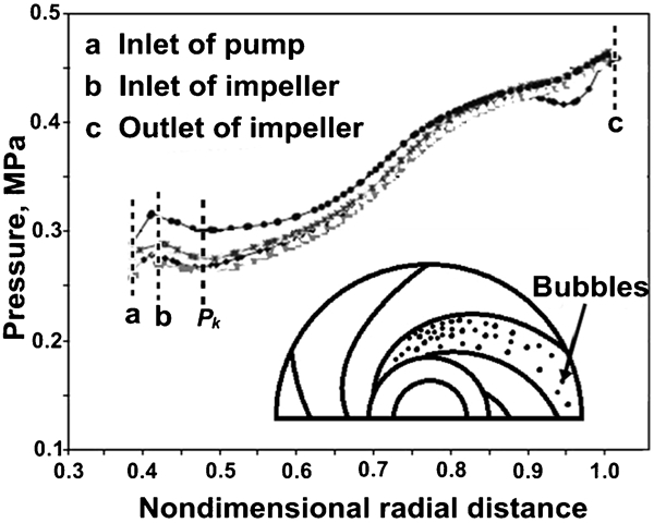
Circumferential pressure distribution in pump
Further evidence of cavitation erosion effects on the impeller is that all the damaged sites concentrate along the small channels. It is because that pressure in the small channels fluctuates more intensively than that in the large channels. The impeller of the failure melt urea pump is a six-channel closed single suction impeller. The flow velocity is higher in the small inlet channels than that in the large inlet channels. Therefore, the pressure drop is more obvious when the flow channel enlarged, which are prone to induce the cavitation erosion. In addition, the blade shape and inlet angle also have an effect on the cavitation erosion to the impeller.
Chemical media effect on failure
The composition of chemical media affects formation of the bubbles in the pump and the Pv value of the liquid. For example, the addition of the chloride ions can cause pitting on the surface of stainless steel, 6, 7 and the pits will increase the probability of the cavitation nucleation and raise the primary cavitation pressure, which is not good for the pump. 8 In addition, while the NH3/CO2 or the H2O/CO2 ratios lose balance, as well as the inlet liquid level of the pump fluctuates largely in the production of the urea, the number of the free ammonia will increase, which will lead to the vaporisation of the medium. 9
In addition, additives in the urea solution can shorten the service life of the impeller. This must be related with the increase in the number of free ammonia after the addition of the additives, which decreases the Pv of the solution and makes the formation of the bubbles easier.
Corrosion effect on failure
Apart from the direct mechanical damage to the impeller, cavitation erosion can cause indirect damage to the impeller through corrosion. Galvanic couples are formed between the places where the bubbles collapse and the surrounding areas. The bubble collapsed areas are the anodic regions, which are prior to be corroded. As a result, the impeller can be damaged by the interaction of the mechanical erosion and electrochemical corrosion in a short time.
The SEM and EDS results of the damaged holes of the impeller show that there exists a high S content; this must be related to the additives that contain S. The existence of the active S may destroy the passive film on the metal surface, reduce its corrosion resistance and accelerate the damage of cavitation erosion. 10
The melted additives will decompose into gases of NH2CN and H2S,
 . The H2S mainly exists in the forms of S2− and HS− in solution, and they can react with oxygen and produce S. The S will adhere to the surface of the metal, destroy the passive film and accelerate the corrosion of the metal. Meanwhile, the consumption of the oxygen due to the oxidation of S2− and HS− will reduce the passivation of the metal.
10
Therefore, the corrosion rate of metal is hundred times to normal condition after the passive film on the metal surface is destroyed.
. The H2S mainly exists in the forms of S2− and HS− in solution, and they can react with oxygen and produce S. The S will adhere to the surface of the metal, destroy the passive film and accelerate the corrosion of the metal. Meanwhile, the consumption of the oxygen due to the oxidation of S2− and HS− will reduce the passivation of the metal.
10
Therefore, the corrosion rate of metal is hundred times to normal condition after the passive film on the metal surface is destroyed.
Material effect on failure
The collapse force of the bubbles on the surface of the impeller will destroy the protective film and reduce the corrosion resistance of the stainless steel in the solution. The 316L SS has a small amount of δ-ferrite after solution treatment, which is easy to cause the phase selective corrosion in the medium of the urea production. 11 The selective dissolution of the ferrite or austenite phase will occur under the condition that the oxygen supply is enough or insufficient respectively. The difference between 316 SS of the impeller and 316L SS is the C content (the C content is lower than 0·080% for 316 SS, which is lower than 0·030% for 316L). They all belong to the Cr–Ni austenite SS, and their as casted solution structures are all austenite with a small amount of δ-ferrite. From the metallographic analysis, it is noticed that there exists the ferrite phase selective dissolution on the impeller material.
In brief, the main reason for the failure of the impeller of the melt urea pump is the cavitation damage. Moreover, the existence of the S containing additives may destroy the passive film on the metal surface and reduce its corrosion resistance. The interaction between the cavitation erosion and corrosion makes the impeller of the melt urea pump out of work in a short time. In addition, more detailed analyses and attentions are needed to prove that the additives increase the number of the free ammonia and decrease the oxygen content in the urea solution.
Conclusion
The material of the impeller is 316 SS, not the reported 321 SS.
The damaged impeller has many honeycombed holes, which is a typical feature of cavitation erosion.
The main failure reason of the impeller is the cavitation erosion, and the electrochemical corrosion of the medium also accelerated the failure of the impeller.
The failure of the impeller is not related with the as casted defects of the material because there is no obvious as casted defects are found in the material.
Suggestions
The following measures should be adopted to improve the resistance to the cavitation erosion:
Optimise the structure from the pump's inlet to the impeller.
enlarging the flow area and the radius of curvature of the pump's inlet section to decrease the flow velocity and pressure variations
streamlining the flow channel
improving the surface smoothness of the inlets of the impeller and blades.
Use the material with good resistance to the cavitation erosion. Generally, the higher the hardness of the material is, the better the cavitation erosion resistance is.
Monitor the variation of Pv of the solution after the addition of additives.
Study the effect of the existence of the active sulphur element on the passive film in order to take appropriate measures.
Footnotes
Acknowledgements
This work was supported by the National Natural Science Foundation of China (grant no. 51131008). The authors also gratefully acknowledge the help of C. Niu and S. Q. Xu.