
Abstract
The tribological characteristics and wear mechanisms of AISI 5140 steel at ambient temperature were investigated using a home built ball on disc tribometer under constant normal loading and rectangular wave loading respectively. The worn surface and wear debris collected from the disc were studied using scanning electron microscope. Results show that the friction coefficients under the constant normal force correspond to the traditional theory. The coefficients all exhibited increased normal loads, whereas under the rectangular wave condition, the highest coefficient appeared when the peak value of the periodically alternative load was 90 N. The different underlying wear mechanism under different loading conditions was explored. It was found that abrasive wear was the main mechanism in the constant loading, whereas severe plastic deformation and adhesive wear were the main wear mechanism in the rectangular wave loading cases. This phenomenon can be attributed to the role of debris in the ‘lubrication’ process under the rectangular wave loading conditions.
Introduction
AISI 5140 steel is widely used in the machine manufacturing industry and exhibits good mechanical properties, such as easy workability, comparative excellent plasticity and toughness under certain heat treatments. Owing to that, AISI 5140 steel is always employed in gear assembly. However, machine components are influenced by rubbing, which results in the severe wear. To prolong the service life of machine, researchers have studied the influence of normal loads, velocities and temperatures1–4 on friction coefficients and wear mechanisms. Furthermore, studies conducted in the past decade have focused on two or more factors that simultaneously affect friction coefficient and wear mode. Cozza et al.5–8 considered the load factor with the particle and found that the degree of microrolling had an obvious influence on the friction coefficients. Milan et al. 9 simultaneously considered the temperature, normal load and preoxidation as influencing factors. However, due to its low anti-wear property, many investigations used surface modification10–15, such as ion nitriding10–13, to improve the fatigue, wear and corrosion properties. Ion nitriding results in the formation of a compound layer on the surface and subsurface 16 . The dry sliding behaviour of the nitrided steel has been investigated in different studies. The particle size of the wear debris has also been considered as an important factor in wear mechanisms. Many researchers have studied the size7,16–17, shape 18 , concentration 17 and hardness19–21 of the particle on abrasive wear. However, unfortunately, these studies all used constant normal loads to investigate friction and wear behaviour. Few studies showed in public investigated the behaviour under periodically alternative loading condition. In the practical working environments, many machines and components are subjected to varying loads. Take the mating gears, for example; some teeth in these gears are meshed and experience high force at the beginning. With the continuing motion of the gears, the teeth do not mesh and the force significantly decreases to a low value. Thereafter, the teeth mesh and separate repeatedly. Goto and Amamoto22–23 studied the effect of varying loads on wear resistance. However, their studies primarily introduced the effect of sliding distance under low loads on the wear mode, but the change of friction coefficients was barely discussed.
This work used a home built tribometer to test. Two different loading conditions were used in the experiment, and one was periodically alternative load. The purpose of the experiment was to investigate the tribological characteristics and wear mechanisms of the AISI 5140 steel under different loading conditions. After the tribometer tests, the scanning electron microscope (SEM) was used to analyse the worn surface and the wear debris collected from the surface.
Experimental
Apparatus
The ball on disc type friction and wear apparatus employed in this experiment were home built, and its schematic diagram is shown in Fig. 1. The highest applied load was 150 N with an accuracy of ∼1 N. The ball was kept still with the disc and was rotated by a main shaft controlled by a servo motor through pulleys. The sliding velocity could be adjusted to a maximum of 300 rev min− 1. The specimen disc for the experiment was fixed on the main shaft with the ball placed into the upper loading arm. The load applied on the surfaces between the ball and disc was controlled by a pneumatic motor. The device installed in the loading arm was a ‘loading controller’. This controller moves owing to the differential pressure. Under the alternative loading conditions, the loads between low and high levels change because of the movement of the loading controller.
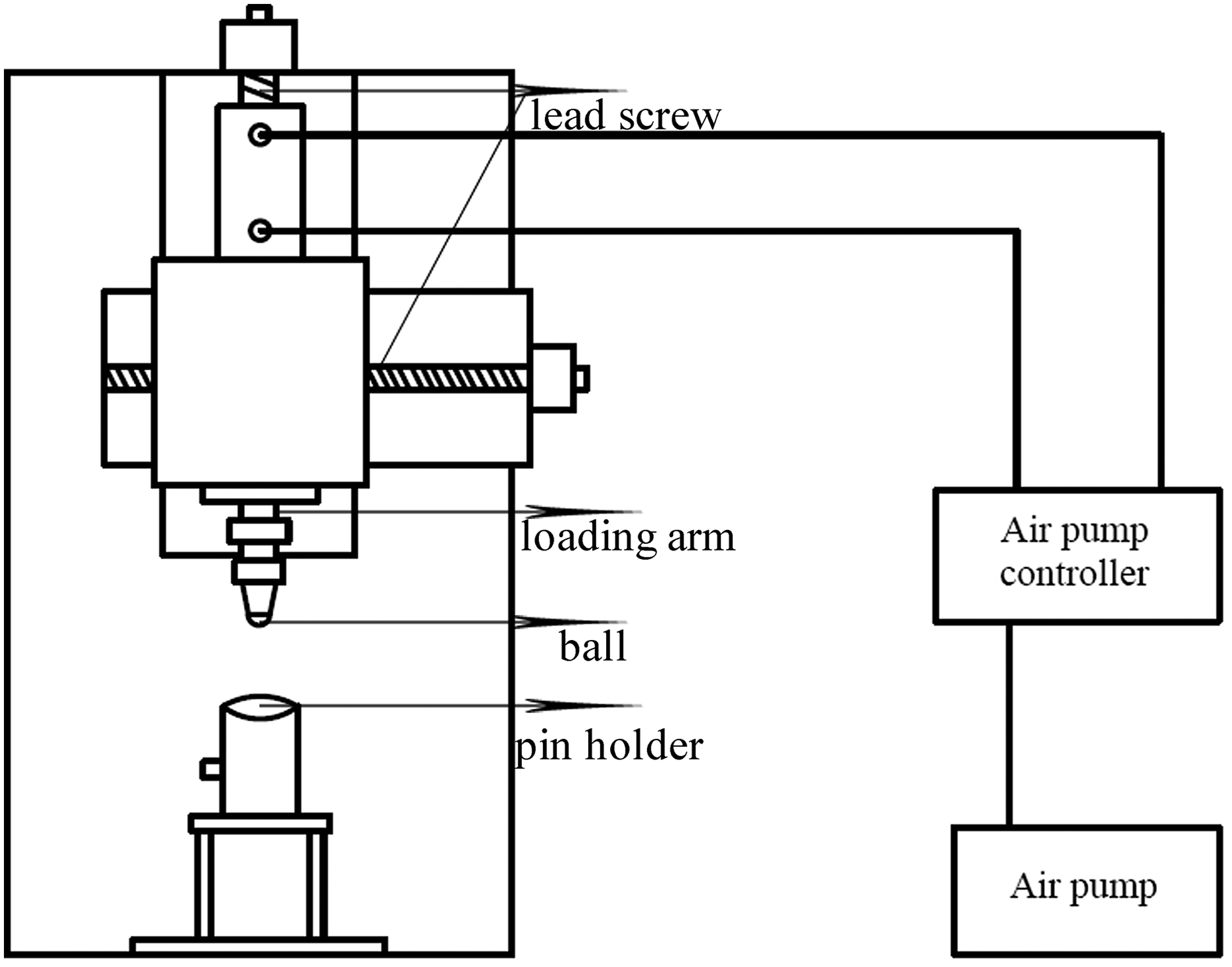
Schematic diagram of ball on disc tribometer
Specimens
The material used in the experiment is the AISI 5140 steel bar with the following chemical compositions (in wt-%): C 0·42, Si 0·26, P 0·009, S 0·006, Ni 0·01, Cr 0·98. The bar material was austenitised at 1123 K for 40 min, followed by quenching in the oil and then tempering at 473 K for 120 min. Then, it was cut into samples in the form of circular discs (Φ30 mm × 3 mm) with the wire cutting machine. This heat treatment was used to remove the inner stress and gave the AISI 5140 steel microstructure with hardness of ∼380 HV0·3. All the samples were carefully ground to a final surface finish of 0·5 μm.
Friction and wear test
The purpose of this experiment is to investigate the characteristics of friction and wear mechanisms under periodical changing loads. The ball on disc tribometer is one of the most commonly used wear test rigs. The tribometer used in the experiment can provide rotational speed ranging from 0 to 300 rev min− 1 and loads ranging from 20 to 150 N. Traditional tribometers support only constant value normal loads during test, yet this equipment can support periodical changing loading conditions and closely simulates the real working environment. Several kinds of waveforms are programmed in the computer and can be chosen to simulate the working condition. In order to study the friction and wear behaviour of the mating gears under more practical condition, rectangular wave loading was chosen in the experiment, and the constant normal loading condition was selected to have a comparison with it. Their shapes are illustrated in Fig. 2a and b.
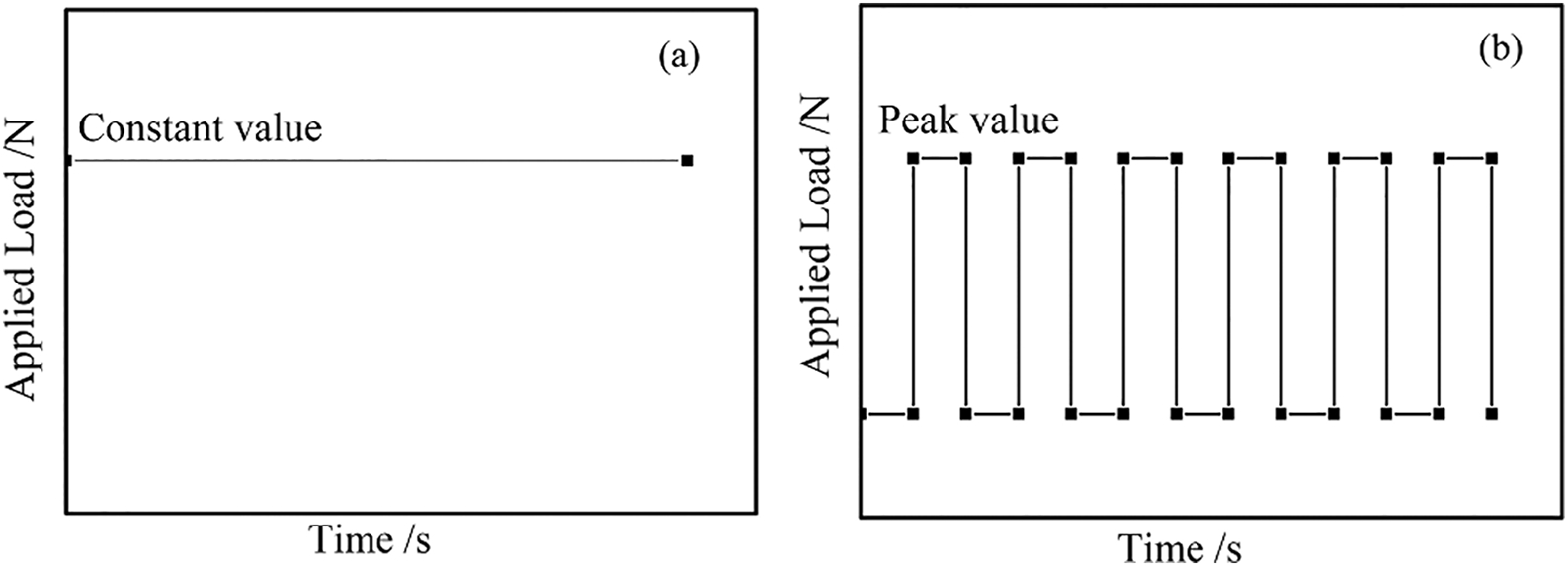
Schematic diagram of a normal loading condition and b rectangular loading condition
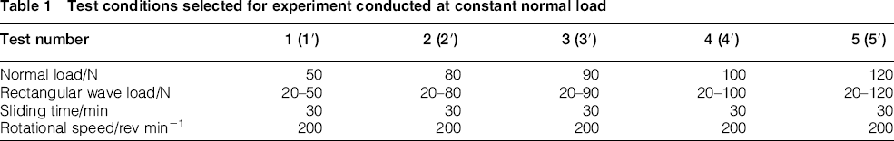
Friction and wear tests were performed in the ball on disc type tribometer under dry sliding conditions at room temperature. The ball is AISI E52100 steel with a 6 mm diameter. The AISI 5140 steel disc was rotated against a fixed E52100 steel ball to form a friction pair. The rotational velocity in the test was 200 rev min− 1. The peak values under the rectangular wave condition were 50, 80, 90, 100 and 120 N and the same in the corresponding normal load conditions. Both the disc and ball samples were cleaned in an ultrasonic cleaner before the tests. The experimental parameters are shown in Table 1.
Test conditions selected for experiment conducted at constant normal load
Results and discussion
Friction coefficients
Figure 3a shows the friction coefficient of the AISI 5140 steel disc against the E52100 steel ball under different normal loads under constant loading condition. It is seen that the friction coefficient was ∼0·12 at different loads. The coefficient had a tendency to increase rapidly at the beginning and then decreased slightly. The coefficient eventually increased and kept constant. This tendency corresponded to the traditional theory. Figure 3b shows the coefficient under rectangular wave load condition. The coefficient was low at the beginning because of low load and then quickly increased. The coefficient then decreased to a low lever again because of the alternative loads. The shape of the coefficient was the same with the rectangular wave load. The highest coefficient did not exist at the largest load. It is clearly seen that in the three middle waves, the highest coefficient exists under 80 and 90 N, and the highest in 90 N at last.
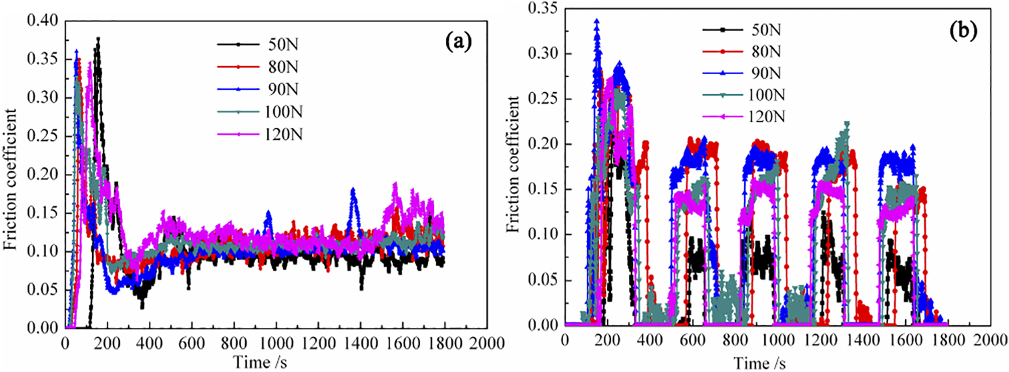
Coefficient of a constant wave and b rectangular wave
Friction load and wear loss
Figure 4 shows the friction load under constant wave and rectangular wave loaded respectively. The shape of the friction load is similar to the friction coefficient. Figure 4a exhibits the friction load of the constant wave. It is clearly seen that the curve increased initially, then decreased slightly, and stabilised at last. The friction load curve shown in Fig. 4b was different from the friction coefficient. The highest value existed under the 120 N condition.
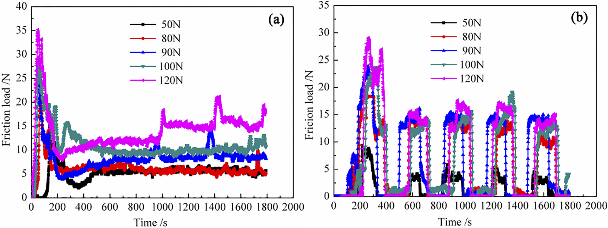
Friction load of a constant wave and b rectangular wave
Figure 5 shows the wear loss under different loading conditions. It is observed that with increasing the normal load under the constant wave, the wear loss is more accordingly. However, under the rectangular wave, wear loss increased in the peak value of 120 N followed by 90 N. The wear loss under the rectangular wave loading condition was all ∼0·01 g, while the max loss under the constant loading condition was 0·05 g. It is clearly seen that the wear loss under the constant condition was higher than that under the rectangular wave correspondingly. In addition, in the constant condition, the wear loss increased dramatically after the peak value was 90 N.
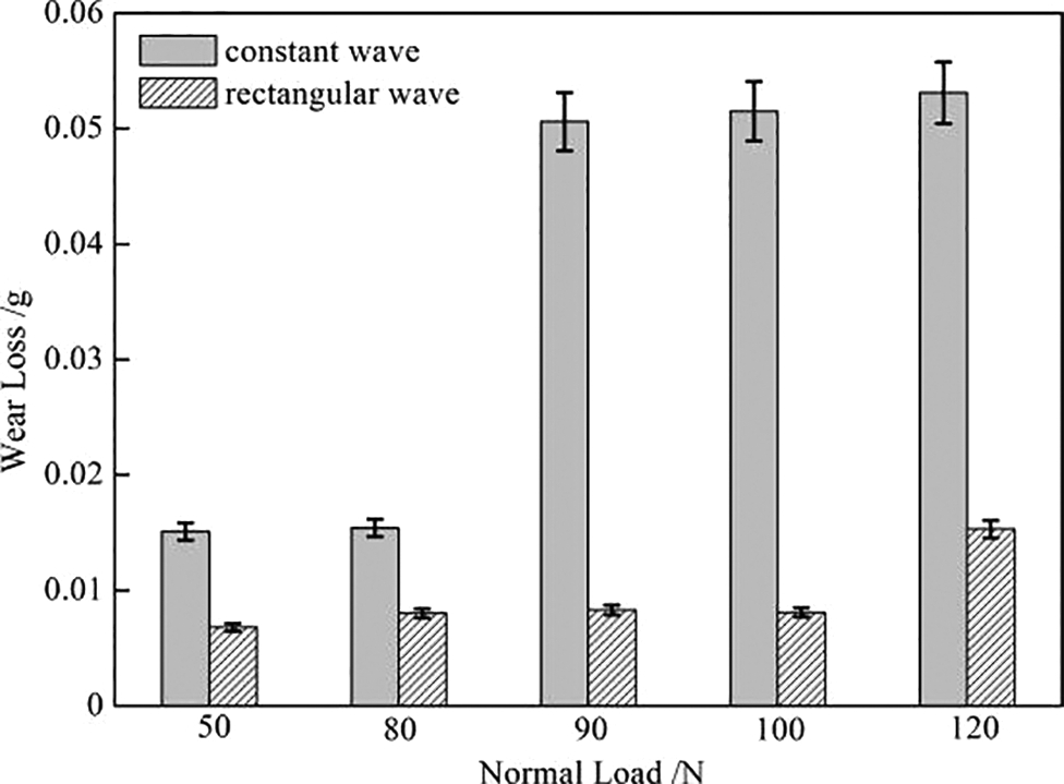
Wear loss of constant wave and rectangular wave
Analyses on worn surface and wear debris under constant wave condition
The characteristics of the worn surface have close relationship with wear mechanisms. Figure 6 shows the worn surface of the discs after sliding for 30 min under constant wave condition. The worn surface under normal loads of 50, 90 and 120 N were taken as examples. It is observed that the surface was rather smooth and only a few wear debris under 50 N from Fig. 6a, while Fig. 6c shows more obvious grooves on worn surface under 90 N. When the normal load increased to 120 N, wear debris increasingly adhered to the surface and more deep grooves existed. These observations indicated that in low loads, such as 50 and 90 N, wear debris was almost uniform, small sized and stuck to the surface loosely. However, in the high loads, such as 120 N, increased wear debris with varying sizes strongly adhered to the surface. The above results and analyses showed that the wear mechanisms change with increasing normal load during the friction tests. Under normal loads of 50 N, mild abrasive wear mechanism dominates the process, while under 90 N, the grooves indicated plastic deformation and adhesive wear in addition to abrasive wear. Under 120 N conditions, severe abrasive and adhesive wears occurred as shown by varying sized wear debris and deep grooves.
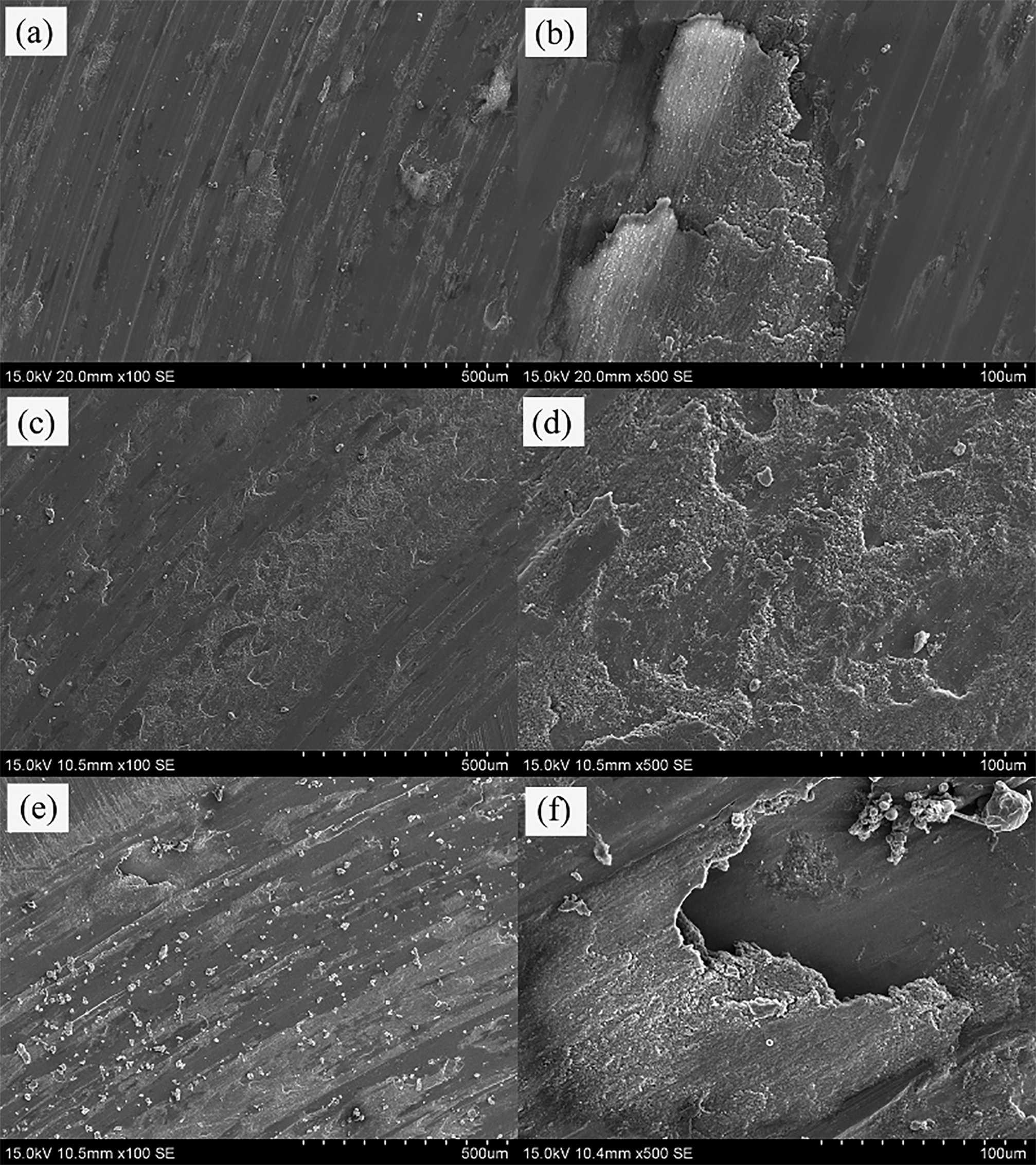
SEM images showing worn surfaces of discs under constant wave condition under a, b 50 N; c, d 90 N; and e, f 120 N
Analyses on worn surface and wear debris under rectangular wave condition
Figure 7 shows the microscopic observation of the worn surface of the discs after sliding for 30 min under the rectangular wave condition. The same different loads (i.e. 50, 90 and 120 N) were also used as examples. It is clearly seen that the most severe wear exists in the normal load of 90 N (Fig. 7c and d) compared with 120 N. More deeper grooves could be observed on the worn surface under 90 N than under 50 and 120 N. Furthermore, with increasing the normal load, the wear debris more strongly adhered to the surface.
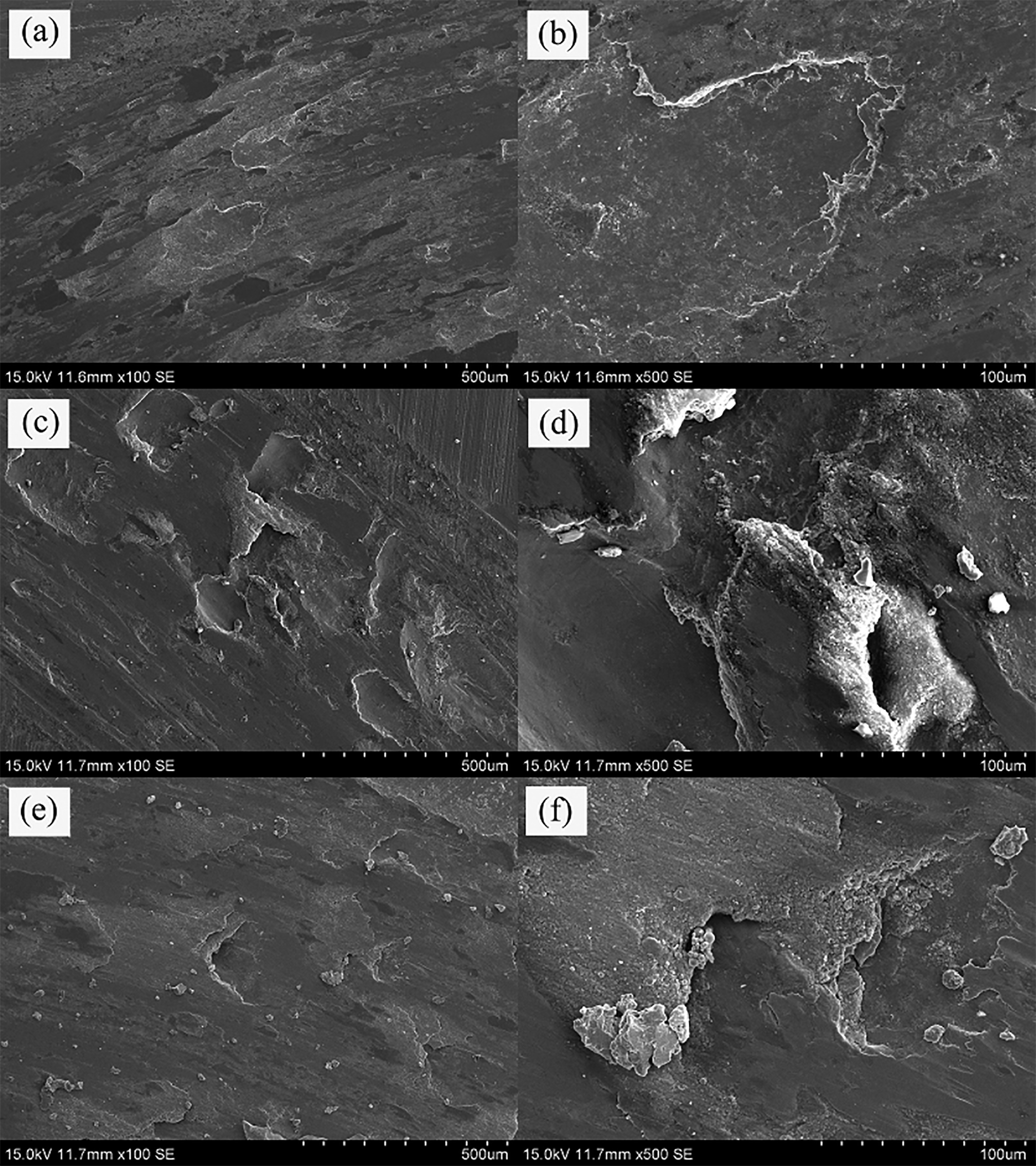
SEM images showing worn surfaces of discs under rectangular wave condition under a, b 50 N; c, d 90 N; and e, f 120 N
Compared with the SEM images under the same normal load, more severe scratches with less wear debris were observed on the worn surface. In the case of 50 and 90 N, the wear mechanisms were apparently plastic deformation and adhesive wear, while under the normal load of 120 N, the wear mechanisms were adhesive and abrasive wear.
Additionally, the debris collected from the worn surface of the discs is shown in Fig. 8, which originated from the damage of in contact brittle asperities between friction surfaces. It is seen that the debris is biggest under the normal load of 50 N, whereas the debris is the smallest under the 120 N condition. In addition, with increasing normal load, the wear debris varies and has higher density.
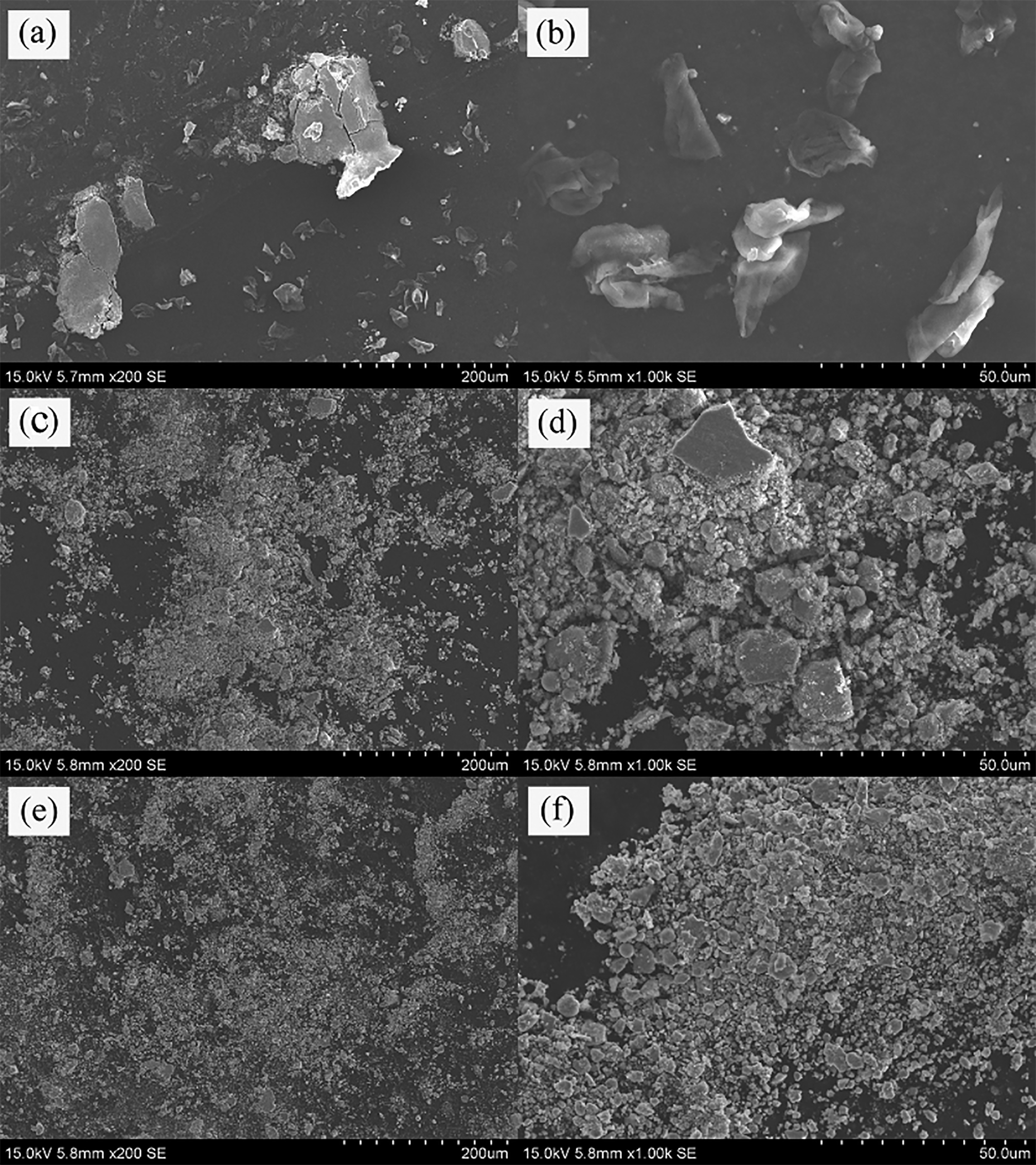
SEM images showing wear debris of discs under rectangular wave condition under a, b 50 N; c, d 90 N; and e, f 120 N
The results and analyses of the SEM images indicated that the wear debris had a notable influence on the friction coefficient and wear mechanism. The 120 N normal load caused severe plastic deformation on the disc, and the two-body (ball disc) contact rapidly became a three-body (ball wear debris disc) system. With the test went on, more and more wear debris were generated. The 120 N condition made the debris smaller, and the wear debris filled in the surface between the contact surfaces and played a role of ‘lubrication’ when the alternative load became 20 N. The debris transformed the dry sliding friction to rolling friction. Thus, the friction coefficient at the normal load of 120 N under the rectangular wave was comparatively low. Although the debris of 50 N normal load is the biggest, the peak value of the alternative load was low. According to the traditional friction law, the friction coefficient was a direct ratio of normal load. So, its coefficient was lower than that under 90 N.
Conclusion
Dry sliding wear experiments were performed under different load conditions to study tribological characteristics and wear mechanisms of 5140 steel discs.
The friction coefficient under the constant wave condition corresponds to the traditional theory, i.e. the friction coefficient increased with increasing normal loads. However, the coefficient under rectangular wave loading conditions differed. Under the peak value of 90 N, the friction coefficient was at the highest because wear debris became small with increasing normal loads. Thereafter, when the alternative load turned into 20 N, the debris travelled to the interface between the ball and disc and completely filled the contact surface. The debris converted the two-body system into a three-body system playing a ‘lubrication’ role. The main wear mechanism under the constant wave condition was abrasive wear. Plastic deformation and adhesive wear were also included. However, under rectangular wave, plastic deformation and adhesive wear were the main wear mechanism. The abrasive existed initially and then the debris eventually became the ‘lubrication’; thus, the abrasive wear was not notable. The wear loss under the constant wave condition was larger than that in the corresponding normal load under the rectangular wave condition. The wear loss under the rectangular wave loading condition was ∼0·01 g, while the max loss under the constant loading condition was 0·05 g. In addition, in the constant condition, wear loss increased dramatically after the normal load was 90 N.
Acknowledgements
This work was supported by the SKPBRC (grant no. 2013CB733000) and NSFC (grant no. 51171163/51271161/51121061).