
Abstract
An innovative means of measuring the end-forces in a softened wood specimen during a bending process has been developed, incorporating a resultant end-force sensor. The impact of end-forces on wood deformation and associated bending performance has been investigated, and a correlation was found to exist between end-force and bending performance. The technique enables the systematic control of axial compression end-forces so that bending induced wood failure, as measured by longitudinal strain at the convex edge, can be minimised. While incorporating traditional manual end-force adjustment, it is envisaged that that this technique could facilitate automation of the bending process. Friction was identified as a significant impediment to the establishment of a reliable relationship between end-force and wood strain during bending.
Background and previous studies
The field of wood bending mechanics has been developed over many years, but often in a fragmented manner. There is some published work exploring mechanical behaviour of softened wood and strain development during bending (e.g. Prodehl 1921; Peck 1950; Fessel 1951; Teichgräber 1953; Kollmann and Cote 1968; Stevens and Turner 1970; Bodig and Jayne 1982; Dinwoodie 1989; Makinaga et al. 1997; Wood Handbook 1999). To further develop the understanding of the mechanics involved in a bending operation, the forces needed to complete a bending operation should be examined in relation to their affect on wood strain development and associated bending performance. Possibly the most important set of forces required for bending are the forces applied by the wood support rig. A wood support rig is used to restrict and control the amount of lengthening of the wood specimen during bending. As described in much of the wood bending literature, it is an essential piece of bending equipment. Stevens and Turner (1970) claim that controlling the length and longitudinal tensile strain in the vicinity of the convex surface of a wood specimen during a bending operation is imperative as:
too small an end-force causes longitudinal tensile failure
an excessively large end-force causes premature longitudinal compressive failure
the smallest radius of curvature for any piece of wood is reached when both the inner and outer surfaces are on the point of fracturing
adjusting end-stops can be used to regulate the amount of end-force and thereby impose the maximum permissible compression on the concave surface of a bend, without, at the same time, inducing such stress on the fibres near the convex surface as to strain them beyond the limit.
There is experimental confirmation in the literature of the necessity for a wood support rig (e.g. Wangaard 1952; Jorgensen 1968; Kollmann and Cote 1968; Stevens and Turner 1970); these experiments commonly compared radius of curvature between bending with and without a wood support rig. There are also some experimental data where end-force has been measured during various bending experiments (Kingston 1939), although without end-force being considered as an experimental variable.
No experimental evidence was found in the available literature that investigated the affect of end-force on actual wood deformation (i.e. magnitude of wood strain) during bending and associated bending performance. If evidence can be obtained that indicates a strong affect of resultant end-force on wood deformation, then an optimum magnitude and rate of resultant end-force could be determined that ensures a sufficient compressive restraint to the tensile strain development without causing excessive compressive failure.
Experimental evidence would offer a more precise understanding of how end-force can be effectively used to improve bending performance, and therefore would be very advantageous for industrial bending processes by aiding in the design and construction of future bending equipment.
Introduction
A correlation has been found to exist between wood deformation end-forces and associated bending performance. A resultant end-force measuring system was developed to be used in association with a centre loading bending machine, where a force is applied centrally via a bending form with the wood specimen supported by a metal strap with an end-force adjustment mechanism. Force equilibrium is provided by two metal rollers that engage with the metal strap (Fig. 1). The REFS incorporates two compression loading sensors attached at each end of the strap, and screw based position adjustment, and was developed to investigate the optimum magnitude of overall end-force during bending. Experimental evaluations were completed on the REFS to find whether end-forces can actually be measured accurately and repeatedly.
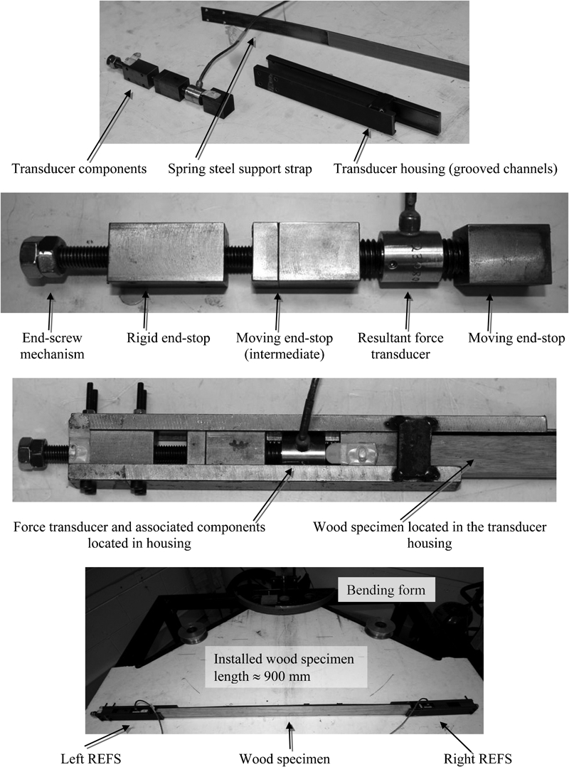
Resultant End-Force Sensor (REFS) designed and built for end-force experiments (bottom image: REFS incorporated into a centre loading bending machine)
Resultant end-force measuring system
The resultant end-force measuring system prototype is able to apply, control and measure resultant end-force (Fig. 1), and was designed to integrate with the common centre loading bending machine, with adequate strength for the type, size and required bending radius of the wood species investigated in the performance trials.
As the centre loading bending machine uses a wood support rig with two adjusting end-stops, two resultant end-force transducers were required. A commercially available force transducer was identified that was of suitable size, force capacity and cost. The maximum load on each resultant force transducer was estimated to be 6,000 N from preliminary calculations. Interestingly, the force transducer that most closely met this criterion has a capacity of 44,500 N (transducer make and model: A.L. Design Inc. ALD-STUD 10,000 lbf capacity at accuracy of ±0·06% of full scale; serial nos. 230808 and 230809).
The support housing for each transducer was designed to accommodate its salient functional principles:
ensuring that each transducer only measures end-force in the longitudinal direction of the wood bending specimen
locating the adjusting mechanism and transducer within the same end-stop, and at both ends of the support strap due to bending throughout the wood specimen.
Both prototype REFS sensors (Fig. 1) were assembled by screwing steel blocks onto the two bolt ends of each transducer, and then locating these blocks within grooved channels in the upper and lower guides using a sliding fit. This arrangement allows axial sliding movement, without lateral movement, of the transducer. The grooved channels and sliding blocks were well lubricated to reduce friction effects. End-force adjustment was made using an adjusting screw, mounted on the stationary end-stop and connected to the trailing end of the force transducer. In order to ensure the upper and lower guides maintain their parallel relationship during a bending operation, small steel plates were welded between the guides on each side of each sensor.
Performance trials of resultant end-force sensor
After manufacture and assembly of the resultant end-force sensor, two performance trials were conducted to ensure correct sensor function.
Performance trial no. 1
A commercial material testing machine applied specified forces to each resultant end-force sensor to enable a calibration check of the sensor transducer. Five cycles were completed with 34 measurements taken in the range 500 N to 31,000 N, resulting in a mean error of 0·76% with a 1·18% standard deviation. The relative error between the material testing machine and resultant end-force sensor decreased with applied force and were within similar magnitudes compared to the manufacturer's specification of the transducer. This result revealed adequate sensor performance concerning accurate measurement of axial forces.
Performance trial no. 2
This experimental trial assessed whether friction between sliding components of each sensor interferes with the measurement of end-force, and subsequent accuracy of the sensor.
The force measured by the transducer was constantly measured, while the position of the end-stop was adjusted from one end of the sensor's guide mechanism to the other end, without purposely applying any external end-force. The transducer was connected to a data acquisition system to enable continuous force measurement. This trial was completed for each sensor.
The measured forces were less than 5 N, on average, with peak forces no higher than 10 N, indicating that friction between sliding components are practically negligible, with respect to the expected end-forces to be measured by the REFS (Juniper 2007).
Both resultant end-force sensor performance trials demonstrated acceptable functional performance with an associated low error for each REFS.
Performance trials of resultant end-force measuring system
End-force investigations were completed using a centre loading bending machine to complete a series of bends using a range of end-force magnitudes. A bending radius was selected to promote tensile wood failure at lower end-force magnitudes and compressive or shear failure at higher end-force magnitudes. During each bend, an experimental strain analysis and a visual assessment of failure were conducted.
It is postulated that the experimental strain analysis and visual assessment results can be used to develop the understanding of how end-force effects wood bending deformation. If end-force does affect wood deformation then there is likely to be an optimum end-force magnitude.
The rate of adjusting the magnitude of end-force that is required to maintain a constant end-force magnitude was recorded during each trial. As such, the optimal rate of end-force adjustment associated with the optimum end-force can be determined. This is of significant relevance for commercial bending machine development; however, the determination of optimum end-force rate of adjustment is outside the scope of the current paper.
For these trials, experimental bending equipment was capable of: bending wood in a controlled, repeatable manner; applying and measuring end-force; and, measuring wood strain during bending.
After each bend, the type of wood failure mode was recorded and the moisture content near the strain measurement location was obtained using the method described in AS/NZS 1080·1:1997.
The visual assessment involved recording the type and size of the initial wood failure nearest the strain measurement location. A series of assessment systems have been reported in the available literature (e.g. Wangaard 1952; Mendoza 1984; Natividad 1989; So and Chai 1995). The visual assessment process developed by the authors (Juniper 2007) applies a rigorous approach to failure determination by considering the amount of post-bending preparation required in a commercial bending context.
The selected wood species was Eucalypts regnans and the selected softening technique was microwave softening developed by Cooperative Research Centre for Wood Innovations (http://www.crcwood.unimelb.edu.au/).
To complete the experimental trials, a centre loading bending machine was designed and built, capable of bending softened wood specimens of cross-section 25×25 mm into semicircular shapes of constant radius. The radius selected for the case study was 300 mm. Operation of the centre loading bending machine involved the following steps:
immediately after microwave softening, the specimen was placed in the wood support rig and located against a set of stationary rollers
the constant radius form was hydraulically actuated until it touches the specimen
a central fixing clamp was applied so that the wood and strap were firmly pressed against the form
end-stops were manually adjusted so that they were flush with each end of the wood specimen
bending was initiated using prismatic actuation from the hydraulic piston
radial support clamps were applied to reduce specimen separation from the form.
The prototype REFS facilitated control of the applied end-force throughout the bending process. End-forces were measured and displayed in real time to allow the operator to monitor the end-force adjusting process. A capacitive displacement transducer measured the end-force adjustment rate for each bend.
Strain measurement was completed using an optical, non-contact strain measurement technique (Juniper 2007). A digital camera was located above a strain grid installed onto the surface of the wood specimen. During bending, photographs of the strain grid were taken (Fig. 2). The digital photographs were then processed by a custom written computer code that determined the change in deformation of the stain grid and calculated associated strains.
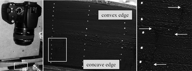
Typical strain grid during wood bending of 25 mm square section specimen. Left: optical strain measurement system. Centre: digital photograph of the strain grid used to create strain development curves. Compression failure cracks are highlighted. Right: detailed view of two ∼3·5 mm long compression cracks in the specimen, corresponding to feature ‘A’ of the strain curves in Fig. 4 (latter stages of the bending operation)
Experimental investigation
Experiment no. 1
A series of bending experiments were completed to assess the value of the REFS based bending system. Eighteen trials were completed at six nominal end-force magnitudes. As the prototype system uses manual end-screw adjustment (Fig. 1), end-force magnitude variations were manually corrected throughout each bend (i.e. manual adjustment was not made to change the end-force within a trial, but rather to attempt to maintain as closely as possible a nominal end-force value). The magnitudes of nominal end-force selected for these trials were based on preliminary qualitative tests that investigated a range of end-forces that caused varying degrees of compressive and tensile wood failure.
The nominal end-force is the end-force that the experimenter attempted to maintain throughout the bending process. Nominal end-force is an extremely difficult parameter to maintain constant due to timber and process variability, so the authors use the phrase ‘applied end-force’ to acknowledge the measured variation in end-force that occurred during bending experiments. Actual applied end-forces were obtained from force transducers within the REFS data acquisition system.
Longitudinal strain at the convex (support strap) edge is a critical parameter in the control of specimen performance during bending, in particular in the prevention of material failure, and was found by extrapolating the strain development curves produced using strain grids (Fig. 2).
A graph of the longitudinal strain at the convex edge of the wood specimen versus associated end-force throughout a bending process was generated to establish whether the REFS based bending system could be used to establish a relationship between these parameters (Fig. 3). If this relationship were to be established, control of end-force could be used as a proxy for control of longitudinal strain at the convex edge and, as such, bend performance.
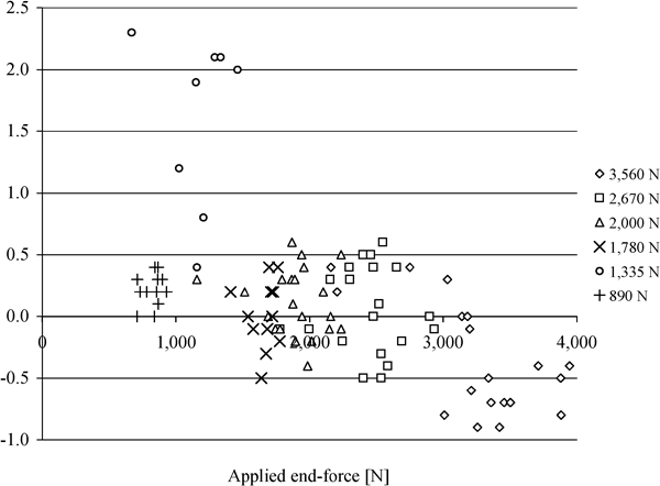
Longitudinal strain at wood sample convex edge versus applied end-force (using REFS). Nominal applied end-loadings – end-screw mechanism adjusted periodically through bend to maintain applied end-force: four trials at 3,560 N, four trials at 2,670 N, four trials at 2,000 N, two trials at 1,780 N, two trials at 1,335 N and two trials at 890 N
However, no discernable relationship between longitudinal strain at the convex edge and applied end-force throughout a bending process was observed in the 18 trials completed. Possible reasons for this inconsistency: frictional effects between wood and bending equipment; and, non-linear and inhomogeneous wood material behaviour. Variability of samples was minimised by using wood from a common source.
The potential influence of frictional effects between the wood sample and the bending strap was subsequently investigated.
Influence of friction on experiment no. 1
The lack of a clear relationship between longitudinal strain and each strain development curve within close proximity to the wood specimen edges (Fig. 1) was likely due to friction between the wood specimen and bending equipment, in particular, the strap. Uncontrolled variables that can affect friction (e.g. wood moisture content, within species variation, and magnitude of applied forces during bending) may result in significant variation in frictional forces and subsequent wood strain magnitudes.
Natural variations in the structure of the wood material caused variation in strain flow uniformity during bending. Figure 4 shows a series of strain development curves at a series of intermediate form displacements (FDs) (where a completed bend occurs at FD≈300 mm) with unusual and non-uniform strain behaviour across the specimen section. Comparing this unusual strain behaviour with the associated digital image of the strain grid identifies minor wood compressive failures at locations that correspond to the non-uniform strain development curves (Fig. 2). These minor compressive failures cause relatively large magnitudes of longitudinal compressive strain at these failure locations compared with the remainder of the wood specimen section.
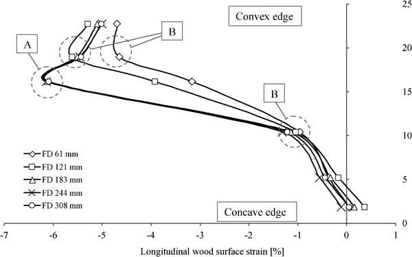
Sample strain development curves, demonstrating the influence of friction and structural variation of a wood specimen across its thickness (concave edge = 0 mm, convex edge = 25 mm, Fig. 2). ‘FD X mm’: X = bending form displacement (Fig. 1) from the start of a bending operation. A: unusual and non-uniform strain development curves due to structural variation in the wood specimen which, in this instance, caused larger compressive strain magnitudes compared to the other strain development curves. B: changes in longitudinal strain linearity due to the influence of friction forces between wood specimens and bending equipment
Friction generated from contact between wood specimens and bending equipment was investigated in friction reduced end-force experiment no. 2.
Experiment no. 2 (friction reduced)
A second experiment investigated whether friction between the bending equipment in contact with the wood specimen was responsible for inconsistent outcomes in the first experiment using the REFS wood support rig.
Frictional forces between wood specimens and bending equipment were reduced by installing polytetrafluoroethylene tape to the wood support rig and bending form where they contact the wood specimen's surface (Fig. 5). Polytetrafluoroethylene tape (commonly known by its DuPont trade name as Teflon tape) has a much lower coefficient of friction compared to steel, for example, the coefficient of friction between Teflon tape and wood is typically in the range 0·05–0·10, whereas the coefficient of friction between metal and wood is typically 0·2–0·6 (Avallone 1996).
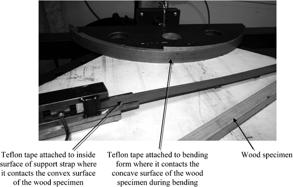
Teflon tape attached to the centre wood bending machine form and steel strap component of the REFS wood support rig to reduce friction forces
The lower coefficient of friction between wood specimens and taped surfaces reduce the frictional forces during bending. If high friction forces are responsible for the unusual and non-uniform strain development (Fig. 3), the friction reduced experiments should result in an improved uniformity between longitudinal strain at the convex edge and end-force.
Fifty samples were used for the friction reduced experiments. A much more uniform relationship was found when compared with the initial experiment (Fig. 6). For each constant applied end-force, each successive bending increment induced an increase in longitudinal tensile strain at the convex edge. Linear trendlines were applied to the final longitudinal strains at the final bend configuration and corresponding R2 values were determined. Although the R2 values do not indicate a highly correlated linear fit, they do indicate an improved fit and a more uniform relationship between longitudinal tensile strain and end-force (Fig. 3). Hence, the friction reduced experiments provide strong experimental evidence that friction forces between a wood specimen and the surfaces in contact with the specimen do influence wood strain development. In addition, the rate of manual end-force adjustment in these experiments was found to have no impact on the results in Fig. 6.
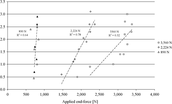
Longitudinal strain at convex edge versus applied end-force for friction reduced sample. Two specimens were bent at each nominal applied end-force. Dashed black lines represent linear trendlines associated with each nominal end-force group with associated R2 values
Magnitude of optimum end-force: Visual assessment
For each bending experiment, a visual assessment of the type of specimen failure was completed to investigate the effect of end-force on bending performance in an attempt to determine the optimum end-force magnitude. The results were:
the smallest end-force that consistently did not promote tensile failure of the timber species used (E. regnans) was above 2,000 N
end-forces less than or equal to 1,780 N almost always resulted in tensile failure, and the smaller the magnitude of end-force below 1,780 N the more severe the tensile failure
significant compressive failures did not occur when end-forces were maintained above 2,000 N and below 3,500 N.
When end-force exceeded a nominal tolerance band within each bending experiment, bending was paused while the end-stop was manually adjusted.
Affect of end-force on strain development
The influence of end-force on bending performance was initially analysed through investigation of how different magnitudes of end-force affect the development of longitudinal strain during bending. The position of the wood sample neutral axis versus bending FD for the three reduced friction end-force magnitude experiments was analysed using the novel optical strain measurement technique (Fig. 2). This analysis enabled the location of the neutral strain axis to be identified throughout the low friction end-force bending experiments (Fig. 7). In addition, the measurement of relative magnitudes of longitudinal tensile and compressive strains during a bending operation provides an indication of bending performance.
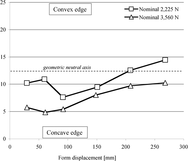
Position of strain neutral zone from the convex (support strap) edge versus FD for two nominal end-forces, each based on the mean of a series of experiments using the friction-reduced bending rig (Fig. 5): the bending form was semicircular with a radius of 300 mm
The majority of data points fall below the geometric neutral axis of a wood specimen's cross-section, indicating that the most of the wood strain is longitudinal compression.
The position of the neutral strain axis, in general, moves away from the support strap as bending FD increases (i.e. as bending progresses, the amount of longitudinal tension increases).
Discussion and conclusions
An innovative wood bending REFS has been introduced. The sensor was used in conjunction with a novel visual strain assessment method to complete a series of end-force experiments that produced the following significant results.
The adjustment of end-force caused a change in the type and severity of wood failure: the larger the end-force, the more severe the compressive failure; and, the smaller the end-force, the more severe the tensile failure.
Experimental strain analysis results found a change in wood deformation (i.e. longitudinal strain magnitude) for various magnitudes of applied end-force.
The influence of friction between the wood specimen and the bending form of a centre loading bending machine has been investigated. Unmodified bending experiment no. 1 produced large strain variations. In particular, this is undesirable for automated processes where high tolerances and low variations are essential for high productivity. Modified bending experiment no. 2 introduced a lower friction between the wood specimen and the bending form, resulting in significantly smaller strain variations.
A method for determining optimal bend end-force and associated end-force displacement has been introduced. In particular, the requirement that end-force displacement be varied throughout a bending process has been demonstrated using E. regnans. In this paper, end-force adjustment was completed using a manual screw-based mechanism. However, once the displacement versus bending time relationship is known, the adjustment process could be readily automated.