
Abstract
Nonstructural components and systems (NCSs) provide little to no load bearing capacity to a building; however, they are essential to support its operability. As a result, 75–85% of the initial building financial investment is associated with these elements. The vulnerability of NCSs even during low intensity earthquakes is repeatedly exposed, resulting in large economic losses, disruption of building functionality, and concerns for life safety. This paper describes and classifies damage to NCSs observed during landmark shake table tests of a full-scale five-story reinforced concrete building furnished with a broad variety of NCSs. This system-level test program provides a unique dataset due to the completeness and complexity of the investigated NCSs. Results highlight that the interactions between disparate nonstructural systems, in particular displacement compatibility, as well as the interactions between the NCSs and the building structure often govern their seismic performance.
INTRODUCTION
Earthquake damage to nonstructural components and systems (NCSs) in buildings pose life safety hazards and can also result in significant economic losses and downtime. In the last eight years alone, damage to NCSs has been extensive. For example, severe damage and collapse of stairs were reported following the 2008 Wenchuan earthquake in China (Wang 2008) and the 2011 Christchurch earthquake in New Zealand (Kam et al. 2011). Damage to elevators was observed after the 2010 Maule, Chile earthquake (Fierro et al. 2011) and the 2011 Tohoku earthquake in Japan (Nakagawa et al. 2013). Severe damage to architectural facades were widespread in modern (less than 25 years old) buildings during both the 2011 Christchurch earthquake in New Zealand (Baird et al. 2011) and the 2012 Emilia earthquake in Italy (Bournas et al. 2013). Extensive damage to partition walls, ceilings and services were reported during the 2010 Maule, Chile earthquake (Fierro et al. 2011), the 2010 Darfield earthquake (Dhakal 2010), and the 2011 Christchurch earthquake (Gould and Marshall 2012). Damage to NCSs can also cripple essential facilities, such as hospitals and schools. For example, extensive damage to NCSs in schools was reported after the 2010 El Mayor Cucapah earthquake (Meneses et al. 2010), while disruption of hospital functionality due to NCS damage was reported at the Tohoku University Hospital after the 2011 Tohoku earthquake (Nagakawa et al. 2013).
Despite these examples and other evidence of the seismic vulnerability of NCSs, knowledge regarding their dynamic response when installed in a building remains limited. Instead, the behavior of NCSs has been characterized mostly with component tests. These have been conducted with the NCS either mounted on a shake table and loaded dynamically or attached to a reaction fixture and loaded directly with a hydraulic actuator. These tests provide highly useful data regarding the component's major modes of response, however they cannot capture the interactions of the single component with the system in which it is installed. These interactions might manifest between the NCS and its support structure or between various NCSs (e.g., stairs with stairwell walls, fire sprinklers with ceilings). Nonetheless, component experiments to date largely form the basis for the state of knowledge regarding the seismic behavior of nonstructural components and systems.
To incorporate system-level interactions, experiments must include multiple NCSs, which are anticipated to interact in the field as well as a physical model of the structure. One such strategy was adopted within the NEES-Nonstructural grand challenge project (CUREE 2014). This work aimed to study the seismic response of ceiling, piping and partition wall systems. The initial emphasis of this experimental program was on evaluating the behavior of the individual components (e.g., Filiatrault et al. 2010, Davies et al. 2011); while in subsequent phases multiple components were paired (Tian et al. 2013). The most inclusive tests in this multi-University project involved shaking a model that comprised two levels of a building with various ceiling, piping and partition systems installed throughout. This test program allowed the assessment of damage states of the NCSs installed in an environment that facilitated system-level interactions, however, only three major types of NCSs were included in the test program.
An alternative strategy is to implement NCSs within a full-scale building experiment. Owing largely to economic constraints and a desire to focus on the structural system behavior, shake table tests of NCSs within full-scale building experimental programs have occurred on only a few recent occasions. Such tests have also typically included only a small subset of NCS types. Examples of NCSs tested in prior building tests include piping, ceilings, exterior walls, and medical equipment (e.g., Matsuoka et al. 2008, Hoehler et al. 2009 and 2012, McMullin et al. 2012, Soroushian et al. 2012, Furukawa et al. 2013). These tests have provided valuable insight regarding the interactions of the considered NCSs with the building structure; however, a test program involving a broad variety of NCSs essential to supporting the buildings functionality has yet to be conducted.
SCOPE OF THIS PAPER
This paper presents the findings of a landmark test program in which a broad array of NCSs were incorporated into a full-scale five-story reinforced concrete building constructed on the George E. Brown, Jr. Network for Earthquake Engineering Simulation (NEES) unidirectional Large High-Performance Outdoor Shake Table (LHPOST; Van den Einde et al. 2004, Ozcelik et al. 2008) at the University of California, San Diego (UCSD). The main focus of this project was to advance the understanding of the seismic behavior of NCSs including their dynamic interactions amongst each other and with the structure. A companion paper (Chen et al. 2016) summarizes the scope of the experimental program including the test building design and construction, instrumentation, test protocol, and response of the structural system. This paper describes the physical damage of the NCSs installed within the test building, categorizes it by level of severity and correlates the resulting damage states with the buildings response. A detailed description of the structural skeleton, NCSs, test protocol, instrumentation and additional measurements and observed damage are available in a series of four technical reports (Chen et al. 2013a, 2013b; Pantoli et al. 2013a, 2013b). In addition, the archiving and navigation of data from these experiments is presented in Pantoli et al. (2016).
CHARACTERIZING NCS DAMAGE STATES
TEST PROTOCOL AND PEAK BUILDING RESPONSE
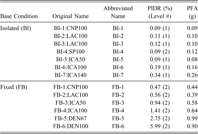
The test protocol consisted of thirteen earthquake input ground motions. The first seven of these were imposed while the building was isolated at its base, whereas the latter six of the motions were imposed while the building was fixed to the shake table. The motions were applied in the east-west direction, which coincided with the building's longitudinal axis. Table 1 summarizes the peak interstory drift ratios (PIDRs) and peak floor accelerations (PFAs) achieved during the base-isolated (BI) and fixed-base (FB) test phases. Floor accelerations and drifts were calculated as the average of the values measured at the four corners of the slab at each floor. It is noted that in some cases the corner values presented some variability. While the PFAs were always attained at the roof, the PIDRs occurred at either the first or the second level, as indicated in Table 1. Particular attention should be given to test FB-5, since the measured PIDR was approximately equal to the target design PIDR (2.5%). Table 1 also notes the abbreviations of the motions that will be utilized throughout this paper. Additional details of the test protocol and design performance target of the building can be found in Chen et al. (2013a, 2016).
Motion protocol, short nomenclature and achieved building performance
POST-SHAKING INSPECTION STRATEGY
Physical inspections were performed after each seismic input motion, with the exception of tests BI-1 and BI-3. Each NCS was inspected by a group of academic researchers and industry partners with expertise closely related to the elements being inspected. Characterization of physical damage during each phase relied upon manual inspections and included:
Taking detailed photographs and notes Physically marking observed damage (e.g., marking of cracks) Evaluating the functionality of items where applicable Identifying the movement of contents or equipment Analyzing image sequences and video data
CLASSIFICATION OF DAMAGE STATES
NCS damage states are classified as either minor, moderate, or severe, with the following general classification criteria:
Minor: Primarily aesthetic or easily repairable damage that would not pose a hazard to occupants. Examples of this damage include easily repairable cracks in partition walls, facades or drywall ceilings and small movement of equipment or contents that do not affect their functionality. This type of damage is color coded with yellow in subsequent plot.
Moderate: Requires repair to ensure optimal functionality of the component, but it does not require evacuation of the building nor pose a life safety hazard. Examples include damage to the connections that require their replacement and damage to access doors that prohibit their smooth or complete opening. Moderate damage is associated with the color orange.
Severe: Poses a significant life-safety hazard directly or indirectly (i.e., threatens safe evacuation). Examples include complete detachment of gypsum boards from partition walls, excessive loss of ceiling tiles, toppling of equipment or contents, complete failure of the opening mechanism of doors, or failure of critical elements of an egress that would render it unusable. Severe damage is associated with the color red.
When possible, severely damaged NCSs were repaired between tests. The repairs for individual NCSs are described in the pertinent sections. Damage states for the various NCSs are then correlated to the demand levels imposed by the structure in terms of either PIDR at the level (L#) where damage occurred (PIDRL#) or PFA at the floor (F#) where damage occurred (PFAF#) depending on whether the NCS is considered mostly drift-sensitive or acceleration-sensitive.
TEST RESULTS: DISTRIBUTION OF NCS DAMAGE STATES
EGRESS
Steel Stairs
Stairs are interconnected from floor to floor; therefore, damage is highly sensitive to the magnitude of interstory drift imposed. The low peak interstory drift ratios (<1.0%) generated while the building was base-isolated and in the first three FB motions resulted in no visible damage to the stair system. However, the final FB tests generated significant damage within the stair system. Figure 1a summarizes the damage states per level as a function of PIDRL# observed during the last three seismic tests. Damage is graded and articulated by color in this figure as either minor, moderate, or severe and the marker placement at each level is located vertically to indicate its location within the stair component (i.e., at the lower flight, landing or upper flight). The damage severity presented in the plot represents the level of the most significant damage developed for the particular tests observed at that location. The schematic presented in Figure 1b shows the location of the subsequent photographs within the stair system. It should be noted that all instances of severe damage compromised access to the building, therefore, a repair was required to allow access to the upper floors of the building, while moderate and minor damage were never repaired. Figure 1a shows that each stair component observed the various damage states at very different PIDRs, with the upper flight-to-slab connection observing severe damage at the lowest PIDRs and the landings attaining only moderate damage at very large PIDRs. It is noted that the interstory drifts shown in Figure 1a are the peak values recorded at each level, and not the actual drifts at which damage occurred, as these were not always directly identifiable.
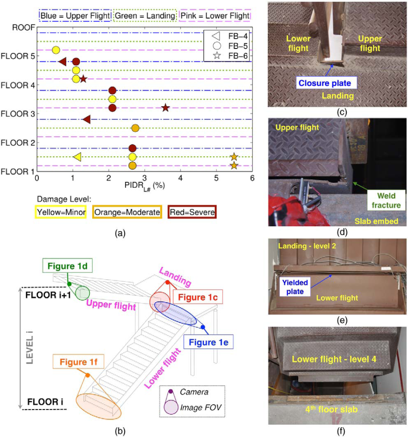
Damage to the steel stairs: (a) damage state versus PIDRL# during the final three seismic input motions, (b) schematic showing the location of elements shown in photos c through f with respect to flights and landing (FOV = Field of View), (c) closure plate of the landing at the first level, (d) weld fracture at the upper flight to slab connection as observed at floor three after test FB-4, (e) yielding of the lower flight to landing plate after test FB-5 (view from bottom), (f) complete detachment of the lower flight from the slab at the fourth level as observed after test FB-6 (view from top).
The onset of damage first occurred during test FB-4. This included one instance of minor damage in the form of detachment of a steel closure plate at level one (Figure 1c) and two cases of severe damage at levels two and four (PIDRL4 ~ 0.8%) in the form of fracture of the vertical weld at the connection between the upper flight stringer and the reduced area angle (Figure 1d; see also Figure 4c in Chen et al. 2016). Although the stair flight detached from the reduced area angle, it remained resting on the slab. Nonetheless, this damage state was deemed severe since even minor horizontal motion, for example due to occupant loading, may result in complete collapse of the flight and cause life-safety hazards for building occupants. This damage was repaired by welding steel plates between the upper flight stringer and the slab embed at the second level and re-welding of the reduced area angle to the upper flight stringer at the fourth level.
Test FB-5 resulted in numerous instances of minor, moderate and severe damage. Handrail fracture (minor damage) was observed at several levels. Moderate damage at the first level consisted of yielding of the washers in the lower flight to slab connection. At the second level moderate damage happened in the form of plastic deformation of the connection plate in the lower flight to landing connection (Figure 1e). Severe damage included the fracture of welds in the lower flight to slab connection and upper flight to slab connection at several levels.
During test FB-6, numerous instances of moderate and severe damage were distributed throughout the stair system. Two cases of moderate damage observed at level one consisted of continued yielding of the washers at the lower flight to slab connection and plastic deformation of the steel plate connecting the lower flight to landing. Severe damage at level three and four consisted of the complete detachment of the lower flight from the structure due to the fracture of the lower flight to slab welds (Figure 1f). This damage was repaired by jacking the lower flight back into place and re-welding it to the slab embed.
Physical inspection performed during building demolition provided access to view steel posts supporting the stair landings. At this time, the landing posts to slab embed welds were noted to have completely fractured at the three lower levels. These damage states are not incorporated in Figure 1a since the test that caused these failures is uncertain.
Passenger Elevator
Functionality of the elevator was evaluated following each test by attempting to move the elevator from its test position up and down and operate the doors at each floor level. Visual inspections were also conducted on the cabin doors, the cabin interior, and along the interior shaft with particular focus on evaluating the state of the rail and its anchor attachment points. No damage was recorded in the elevator prior to test FB-5. Inspection after FB-5 (PIDRL2 ~ 2.7%, PIDRL3 ~ 2.1%) revealed the formation of a small gap (<25 mm) between the cabin doors at levels two and three (Figure 2a) and minor crushing at the top corners of the cabin doors. This damage was classified as minor since it did not impair the functionality of the elevator. However, during test FB-6 (PIDRL2 ~ 6%, PIDRL3 ~ 3.6%), crushing of the elevator doors with the surrounding partition walls continued and the gap between the doors at their base enlarged, with a residual of 200 mm measured at levels two and three (Figure 2b). This damage to the cabin doors eventually resulted in the inoperability of the elevator following this test (severe damage).
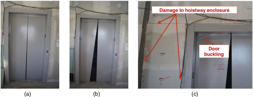
Damage to the elevator: (a) gap between the cabin doors at level three after test FB-5, (b) gap between the cabin doors at level three after test FB-6, (c) damage to the upper west corner of the door and hoistway enclosure at the third level after test FB-6.
ARCHITECTURAL FAÇADES
Levels 1–3: Cold-Formed Steel (CFS) Balloon Framing Overlaid with Synthetic Stucco
Visual inspection of the CFS balloon framing was performed for its accessible components, namely the interior gypsum boards, the exterior finishing system and visible connecting clips with associated powder-actuated fasteners or concrete screw anchors. Results in the following section refer to damage to the sides of the balloon framed facade, which moved mainly in-plane (i.e., the faces parallel to the direction of motion), as these sides experienced more significant damage than the faces moving mainly out-of-plane. During the BI test phase, the only elements of the CFS balloon framing that exhibited damage were the interior gypsum boards. Namely, they suffered minor damage in the form of drywall plaster and tape cracking and incipient screw pullout. Figure 3a depicts the damage state observed for each component as a function of the maximum of the peak interstory drift ratios at the three lower levels (PIDRL1–L3) during the FB tests. Tests FB-1 and FB-2 are grouped together, as their PIDRsL1–L3 were similar. This plot shows that in general damage to the balloon-framed facade is correlated with interstory drift demands, as the intensity of damage increases with increasing PIDRsL1–L3.
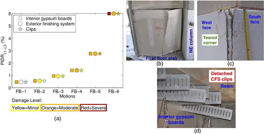
Damage to the balloon framing: (a) summary of damage level for the three primary visible components of the balloon framing (sides moving in-plane), example of moderate damage to: (b) interior gypsum boards (NE = northeast), (c) exterior finishing system, (d) interior connecting clips. (b–d were taken following test FB-6).
Damage to the interior gypsum boards, which was minor during the BI tests, increased as the intensity of the seismic input motions increased. Moderate damage during the FB tests included extensive cracking of corner joints, numerous instances of screw pull-out, fracture and partial detachment of the gypsum panels (Figure 3b). The exterior finishing system at the exterior of the building exhibited minor damage in the form of bulging of the stucco during tests FB-1 and FB-2. During tests FB-3 and FB-4, the stucco continued to bulge and started to show cracks (minor damage). During the last two seismic input motions, complete tearing of the corners where the in-plane and out-of-plane walls intersect was observed at several locations. This type and extent of damage was classified as moderate (Figure 3c). The CFS angle clips connecting the structural slab to the CFS balloon framed studs did not undergo any damage prior to test FB-3. Less than 15% of the clips observed failure in the form of detachment from either the metal studs or the structural elements during tests FB-3 and FB-4. It should be noted that these detachments were concentrated in the plastic hinge region of the beams, where large local structural deformations are expected. Damage in this case was still classified as minor, as a high level of redundancy exists with the relatively tightly spaced clip connections. During tests FB-5 and FB-6, a larger number of clips, ~30% and ~80%, respectively, failed, and for this reason the damage was classified as moderate.
Damage to other components of the balloon framed facade at levels one to three, including its CFS studs and tracks, were not readily visible, as these components were enclosed within the system. It is important to note that during testing the balloon framed facade was observed from the exterior to detach from the foundation early within the FB motion sequence, resulting in a notable isolation of the balloon framed facade from the building. Unfortunately, it was not possible to examine this damage in detail due to limited visibility of the bottom track and studs.
Damage to the balloon framed facade during the last two tests, which was classified as moderate since it does not pose imminent life-safety hazard to occupants, could have been classified as severe considering the perspective of post-earthquake fire protection and the lengthiness of repair downtime and associated costs. In fact, damage to the balloon framing caused individual rooms to suffer reductions in their compartmentation capacity, and this could have had life-threating consequences should a fire occur following an earthquake. Repair of this type of damage would likely require complete demolition and reconstruction of the entire facade. Nonetheless, these are subjective aspects that are best addressed on a case basis.
Levels 4–5: Precast Concrete Cladding Panels
Inspection of the precast concrete cladding panels focused mostly on the detection of damage to the connections and physical damage to the concrete panels, primarily on their interior exposed areas. Exterior inspections of the panels were performed on a limited basis due to time constraints. The bearing connections did not undergo any damage throughout the duration of the test sequence while the more sensitive upper push-pull connections were damaged on several occasions during the FB test phase. Figure 4a summarizes the damage states for the types of push-pull connections installed on the fourth level during the FB tests as a function of the PIDRL4. The fourth story was selected since larger interstory drifts were obtained at this level, and this resulted in a greater damage concentration. Figure 4a also notes when connection rods were replaced.
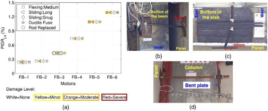
Damage to precast concrete cladding panels: (a) summary of the damage level for final five seismic input motions and three of the connection typologies installed at the fourth level, (b) example of moderate damage to the flexing rod connection with medium length rod (view from bottom), (c) example of moderate damage to a sliding connection with long rod (view from bottom) and (d) example of moderate damage to the ductile fuse (lateral view).
Flexing rod connections underwent moderate damage, corresponding to yielding and permanent bending of the connection rod only during the last two tests (Figure 4b). In contrast, the sliding connections with long rods observed moderate damage in the form of plastic deformation of the rod (Figure 4c) at the onset of the FB test phase, behavior that was expected due to the extreme length of the rod. The snug sliding rod connections remained undamaged throughout testing. The push-pull connections with a ductile fuse attained minor damage for the first time during test FB-3 in the form of small cracking of the panel close to the connection embed. Minor damage to the ductile fuse connection in the form of slight permanent bending of the connecting plate, was also observed after test FB-5. The damage level to the ductile fuse connections was elevated to moderate only during test FB-6: in some cases damage corresponded to larger cracks (≥0.5 mm) in the panel close to the ductile fuse connection embed, while in some other cases it consisted of considerable (≥20 mm) plastic bending of the plate, see Figure 4d.
INTERIOR ARCHITECTURAL COMPONENTS
Ceilings
Inspection teams observed ceiling damage from the floor level and by accessing the plenum space through the removal of select ceiling panels. Damaged ceiling tiles were replaced prior to subsequent seismic tests; however, ceiling t-bars or other fastening elements were not replaced between tests. Ceilings at all stories remained undamaged during the BI test phase. Moreover, the hospital-rated seismically designed ceilings at levels four, five and the penthouse, as well as the powder actuated fasteners and hangers supporting these ceilings remained undamaged throughout the FB testing phase (PFAroof ~ 1 g). It should be noted that generally the upper floors observed larger accelerations, with exception of the last two seismic input motions, when the PFAF# did not increase with the height of the building due to the highly nonlinear structural behavior.
Figure 5a correlates the damage states of the ceilings at the three lower levels to the peak vertical and horizontal (floor level) accelerations of the slab, which they were attached to. Current codes classify ceilings as acceleration-sensitive items and recent experiments have highlighted that they are particularly sensitive to vertical accelerations (Soroushian et al. 2012). Figure 5a indicates that an elevated damage state occurs with increasing PFAF#. It should be noted that the amplitude of vertical accelerations obtained were relatively small, since the shake table did not specifically intend to impose any vertical input motion. As a result, the recorded vertical accelerations resulted exclusively from the dynamic effects created by the movement of the building. Although the ceilings appear sensitive to accelerations, it is important to underline that the ceiling damage observed in these tests was created by the interaction of the boundaries of the ceilings with structural elements and balloon framing.
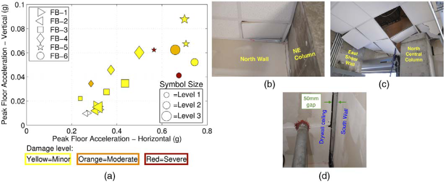
Damage to the ceiling at the three lower levels: (a) summary of damage states, (b) moderate damage at level one after test FB-4, (c) severe damage at level one after test FB-6, and (d) gap between drywall ceiling and balloon framing at level three (moderate damage) after test FB-6 (view from bottom). NE = northeast.
Ceilings at the first level were the most vulnerable to seismic damage since they lacked seismic bracing. The first minor damage to the ceiling at level one occurred during test FB-3. This damage corresponded to small buckling of the tees at two locations near the perimeter. During test FB-4, the damage at this level was elevated to moderate due to increased buckling of supporting tees near the perimeter and the incipient falling of a corner tile (Figure 5b). During the last two tests, the damage was classified as severe and involved collapse of approximately 20% of the ceiling tiles (Figure 5c). These failures were concentrated close to the corner areas.
Damage to the ceilings at levels two and three, which were designed according to modern seismic provisions, was initially observed following the first FB tests and remained mostly minor throughout testing. Damage was in the form of slight buckling of tees in the lay-in ceilings at level two and cracking of tape in the drywall ceilings at level three. In addition, a horizontal gap initiated between the ceiling and the balloon framing at the third floor at one location during test FB-2 (minor damage). This gap continued to widen during subsequent tests. After test FB-6, two locations presented this type of horizontal gap, with a maximum width of 50 mm (Figure 5d). The latter was classified as moderate damage due to the large width of the gap. It should be underlined that this gapping was a manifestation of the interaction between the ceilings and the balloon framing and it was classified as ceiling damage since it created a disruption of the horizontal plane of the ceiling.
Partition Walls
Damage to partition wall subsystems has consistently been observed at relatively low interstory drifts, with minor damage noted in component tests at quite low PIDRs of about 0.1% (e.g., Restrepo and Lang 2011, Restrepo and Bersofsky, 2011, Peck et al. 2012, Retamales et al. 2013). Observations following the seismic input motions imposed during this experiment are consistent with prior component tests in this regard. Figure 6a summarizes the damage states to the partition walls moving in the primary shaking direction during four select motions that imposed a varied level of interstory drifts to the structure.
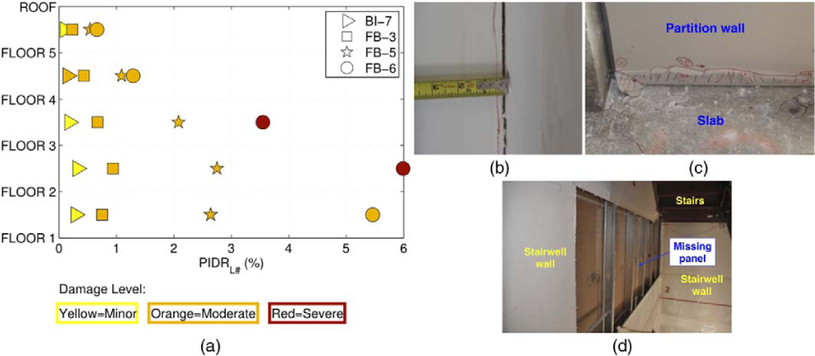
Damage to the partition walls: (a) summary of damage level for select seismic input motions, (b) opening of the gap between panels (moderate damage) after test FB-4, (c) gypsum board corner crushing (moderate damage) after test FB-5, and (d) fallen gypsum board in the stairwell (severe damage) after test FB-6.
This data shows that during the final BI test, mostly minor damage was observed at every level, particularly in the form of joint tape cracking. In addition, gypsum board crushing and damage to the screws around the bottom track (moderate damage) were initiated at the fourth level. During test FB-3, the damage state was elevated to moderate at each floor. Damage included extensive crushing of the gypsum boards and gap opening between gypsum panels (Figure 6b), especially in regions where interaction of the partition walls with other components was imminent, such as at the south side of the stairs, where pounding with the stair landing occurred. During test FB-5, cases of moderate damage (e.g., gypsum crushing at the bottom boundary, see Figure 6c) and severe damage in the form of pull through failure of the screws that caused separation of the CFS studs and gypsum boards were observed. During the last test, severe damage to the partition walls was observed at every level except for the fifth, where damage remained moderate. Severe damage included several instances of complete detachment of the gypsum boards from the CFS studs (Figure 6d).
Level 1: Access Doors
Operability of doors following an earthquake is essential for egress. Therefore, both visual and functionality checks of the access doors installed at the first level were performed during each inspection phase. No damage to the doors occurred up to test FB-4, even though the balloon framing, which the doors were installed onto, suffered moderate damage. Figure 7a correlates the damage states of the four doors with PIDRL1 for tests FB-4, FB-5, and FB-6. It should be noted that, since the balloon framing detached from the foundation early in the FB testing, the actual drift that the doors were subjected to via the balloon framing was less than the PIDRL1 presented in Figure 7a.
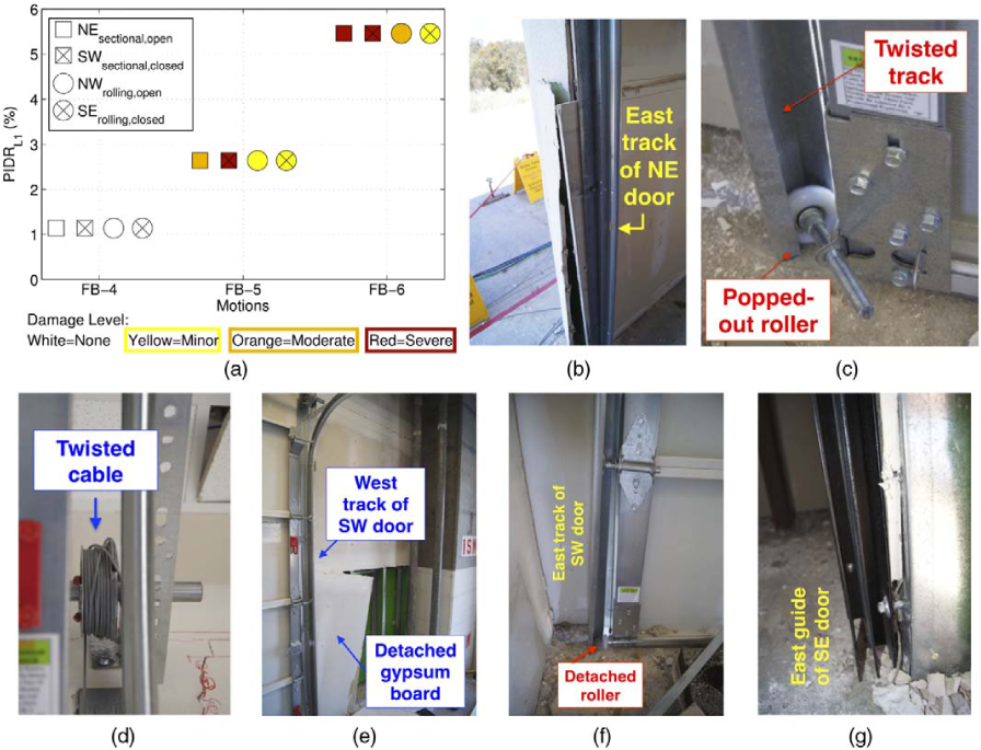
Damage to the doors at level one: (a) summary of damage level for the four doors, (b) east side of NE door jamb after test FB-5, (c) east track of SW door with twisted roller after test FB-5 (d) twisted cable on east side of NE door after test FB-6 (e) south wall at SW door after test FB-6, (f) east track of SW door after test FB-6, (g) east guide of SE door after test FB-6. NE = northeast, SW = southwest, NW = northwest, and SE = southeast.
During test FB-5, all four doors were damaged to varying degrees primarily due to their interaction with the interior gypsum panels of the balloon framing. The north-east sectional garage door that was staged open during testing (NEsectional,open) suffered moderate damage: the track shifted due to the interaction with the gypsum boards and because of this the door was not able to operate smoothly anymore (Figure 7b). The north-west steel rolling door staged open during testing (NWrolling,open) and south-east rolling door staged closed (SErolling,closed) underwent minor damage in the form of widening of the guide rails at the bottom (~10–20 mm). The south-west sectional garage door staged closed (SWsectional,closed) suffered severe damage and was inoperable due to twisting of its track and pop-out of its bottom roller (Figure 7c).
During the most intense test FB-6, both the NE and SW sectional doors were severely damaged and no longer operational. Damage to these doors manifested in the forms of twisting of the pulley cable (Figure 7d), loosening of the support anchors, detachment of the door track from the gypsum board (Figure 7e), and lower roller detachment (Figure 7f). Damage to the opened NW rolling door was moderate in the form of compression of the guiderails due to detachment of panels of the balloon framing. The closed SE roll-up door suffered only minor damage in the form of ~10 mm narrowing of the track at bottom and remained operational (Figure 7g). Severity of damage was more intense for the sectional garage doors and less impacted by the status of the door (fully opened versus closed).
SERVICES
Services were closely examined during each inspection phase. When applicable, functionality or pressure checks were also performed. The most significant observations include the following:
Heating, Ventilation, and Air Conditioning (HVAC): No damage to the HVAC installed at the third level was observed during testing (maximum PFAF4 ~ 0.7 g).
Electrical Distribution System: Remained functional throughout testing at all levels.
Fire Sprinkler System: No drop in hydrostatic water pressure was observed during testing, indicating that no leaks occurred. Minor damage in the form of loosening of the vertical riser during test FB-1 (Figure 8a and b) and displacement of the mineral wool at penetration locations during test FB-2 were observed (Figure 8b).
Gas piping: No pressure drop or damage to either of the two gas pipes was observed prior to test FB-6. Following this final test, pressure in the rigid gas pipe dropped to zero, while pressure within the flexible pipe remained at its pre-test value. The pressure drop was attributed to the fracture at the connection between the T-joint and the rigid pipe at level one (PIDRL1 ~ 5.5%) (Figure 8c).
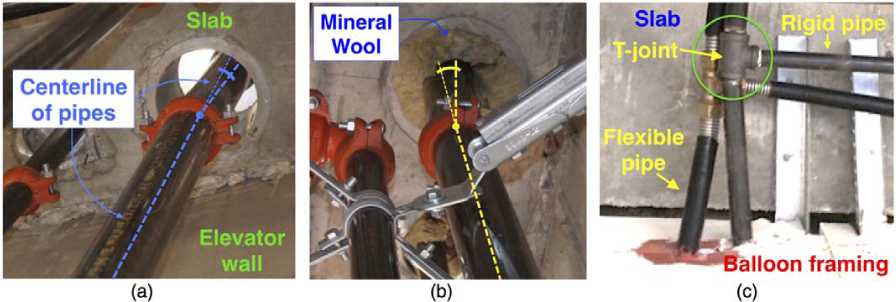
Damage to services (view from bottom): (a) rotation of the riser at junction after test FB-1, (b) nominal loss of the mineral wool at penetration after test FB-2, and (c) permanent bending of the steel pipe at level one after test FB-6.
EQUIPMENT
Level 2: Residential and Laboratory
During each inspection phase, permanent displacement of the equipment installed at level two was monitored and subsequently all the content was reorganized to the initial position. Figure 9a correlates the damage state of the restrained or unrestrained items to PFAF2 and indicates also the peak floor velocity at the second floor (PFVF2). This figure shows that no movement of the items installed at the second level was observed prior to test BI-7. During this test, an unsecured refrigerator in the northeast room displaced permanently ~150 mm. The restrained items did not move substantially up to this point. During the low level FB tests, restrained and unrestrained items underwent only small movements (<30 mm).
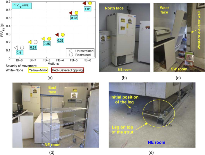
Damage to the second floor equipment and nonstructural contents: (a) summary of severity of movement for restrained and unrestrained items, (b) movement of the unrestrained refrigerator after test BI-7, (c) toppling of a bookshelf after test FB-4, (d) toppling of an unrestrained refrigerator after test FB-6 (excessive rotation of the unrestrained refrigerator can be seen in the right side background), and (e) leg of a piece of equipment on top of the restraining strut after test FB-6.
During test FB-4, the movement of the restrained items remained within the limits imposed by the restraints. The unrestrained bookshelf in the southwest room, however, tipped over (Figure 9c). Test FB-5 caused substantial dynamic and permanent movement of the unrestrained items (<120 mm) including toppling of a large refrigerator. During the final FB-6 test, permanent horizontal displacement of the unrestrained items were as large as 0.3 m and two of the items toppled, namely a bookshelf and refrigerator (Figure 9d). In contrast, during both tests FB-5 and FB-6, restrained items moved only within their limits, and failure of restraints was not observed. In one case, the legs of a large restrained piece of equipment jumped over its slab restraining strut (Figure 9e).
Level 3: Computer Servers
The two computer server units anchored to the third floor slab were closely monitored up to and including test FB-5, after which the servers were removed from the building. In addition to visual inspections, it was also possible to continuously monitor the functionality of one of the units during shaking via a high-speed Internet connection provided by the server manufacturer.
The non-functional unit, whose longitudinal direction was perpendicular to the primary direction of shaking, remained undamaged up to test FB-3 (PFAF3 ~ 0.35 g). Inspection performed following test FB-4 (PFAF3 ~ 0.37 g) revealed plastic yielding of the end plate of the horizontal connection strut (Figure 10a). During test FB-5, (PFAF3 ~ 0.71 g) screw pullout occurred at two locations (Figure 10b and c). Both types of damage can be classified as minor. The functional unit, placed with its longitudinal axis parallel with the direction shaking, experienced no damage throughout testing. In addition, although two errors in data transfer occurred during test FB-5, the unit was able to recover immediately; therefore run-time functionality was not compromised.
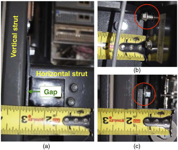
Damage to the non-functional computer server at level three: (a) yielding of the end plate of the horizontal strut during test FB-4, (b) and (c) screw pullout during test FB-5. (Note that the measuring tape indicates inches and not millimeters.)
Levels 4–5: Medical
During each inspection phase, permanent displacement measurements and functionality checks (when applicable) of the medical equipment installed at the fourth and fifth levels were performed. At the end of inspections, all pieces of equipment were staged back in their initial position. For clarity, physical observations of the medical equipment are presented separately for acceleration-sensitive and drift-sensitive items.
Figure 11a summarizes the damage states attained for select acceleration sensitive items installed on the fifth floor and their relationship to the PFAF5 and PFVF5 for the last four tests. Peak absolute velocities recorded at the fifth floor slab are also reported. Acceleration sensitive medical items that underwent damage include:
Patient care beds and stretchers: Two beds were installed at each of the upper stories. At each level, the bed parallel to the direction of shaking was left unlocked before testing while the one perpendicular to it was staged locked. The locked patient bed positioned perpendicular to the direction of motion at the fourth level did not observe significant permanent displacement (larger PFAF4 ~ 0.7 g, larger PFVF4 ~ 1.65 m/s), while the stretcher installed in this fashion on the fifth level toppled during each of the final three tests (Figure 11b). The unlocked units positioned parallel to the direction of shaking rolled during testing, with the amplitude of movement increasing from test to test. During the last two seismic input motions, their movement was so violent that it caused damage to other items. For instance, the impact of the rolling patient bed with a partition wall at the fourth level left a significant hole in the wall, while at the fifth level the patient bed impacted a wall mounted cabinet, damaging its door (Figure 11c).
Carts and shelves: Two rolling carts were installed at the forth level and two shelf units (not on wheels) at the fifth level. At each story, one item was restrained while one was free to move. Restrained carts and shelves at both levels did not move beyond the limits imposed by the restraints. However, the unrestrained cart on wheels placed on the fourth level exhibited movement from the first BI seismic input motion, with the range of its displacements increasing from a few centimeters to several meters during the final test. Movement of the unrestrained unit not on wheels placed on the fifth level was observed from test BI-6 (PFAF5 ~ 0.15 g, PFVF5 ~ 0.42 m/s). Subsequently, this item toppled during the last two seismic input motions (Figure 11d).
Ultrasound imagers: Three nearly identical ultrasound imaging machines were staged on the fourth level, one free to move, one with anchorage designed at half of code-level demand values, and one designed at full code design anchorage strength. The anchored ultrasound imagers remained undamaged, while the free rolling imager moved during all tests. During the last test, the impact of this item against a partition wall generated a large hole in the gypsum board.
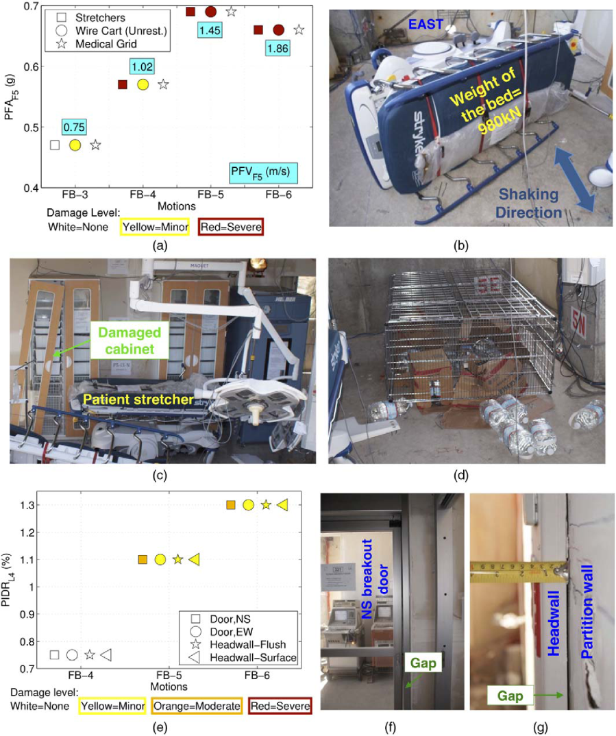
Damage to the medical equipment: (a) damage state versus peak floor acceleration (acceleration sensitive items on level five), (b) toppling of the patient bed at level five during test FB-4, (c) damage to the cabinet door caused by movement of the patient bed during test FB-6, (d) toppling of the wire shelving unit at level four after test FB-5, (e) damage state versus interstory drift (drift sensitive items on level four), (f) gap between the NS door and the door jamb observed during test FB-6, (g) gap between the headwall and the partition wall observed after test FB-6. NS = north-south and EW = east-west.
Figure 11e presents a summary of the damage states observed for select drift-sensitive items installed on the fourth level. Drift-sensitive items that underwent damage were:
Intensive care unit breakout door running east-west, in-plane with shaking direction: This door was staged open before testing and its functionality continually tested following each test. The east-west spanning door remained fully operational up to test FB-5, during which it observed minor damage: the door impacted violently against the door jamb bending slightly the closing mechanism. The breakout mechanism remained functional; however, it was more difficult to release. During test FB-6, the sliding panel derailed. This type of damage was classified as minor due to its ease of repair.
Intensive care unit breakout door running north-south out-of-plane with shaking direction: This door was staged open at the beginning of testing. During test FB-5, inertial forces were large enough to open the breakout mechanism and as a consequence the latch mechanism was inoperable. As the door remained open at the end of shaking, facilitating access to the intensive care unit, this damage was classified as minor. It can be speculated, however, that a failed latch mechanism with the door rendered closed at the end of shaking should be classified as severe, as access would be prohibitive. During the final test FB-6, the door was staged closed. Inspection following this test revealed that the sliding panel was no longer aligned to its track, resulting in a gap between the door and the jamb (Figure 11f). However, the door was easily realigned, suggesting that this damage was minor.
Headwall - flush mounted: This item was installed on the eastern wall of the northeast room at the fourth floor. A hairline crack between the flush headwall and the partition wall formed during test FB-5, and subsequently enlarged during test FB-6 (Figure 11g). This damage is classified as minor as it would not impede the operability of the headwall.
Headwalls - surface mounted: Two headwalls were installed on the southern wall of the northeast room at level four. Differential movements between the various elements of the eastern surface headwall were the primary type of damage observed during tests FB-5 and FB-6. In addition, permanent gaps between the headwall and the partition wall developed. Both types of damage can be classified as minor. No damage was observed on the western surface headwall.
The other pieces of medical equipment (overhead medical equipment support, patient lift, medical booms, surgical lights, etc.) did not undergo any damage throughout testing.
Roof: Penthouse, Air Handling Unit, Cooling Tower
Visual inspection of damage to the three roof-mounted equipment and functionality checks of the cooling tower were performed throughout testing. In addition, the amount of water loss in the cooling tower was also measured. It is noted that the PFAroof attained during tests FB-5 and FB-6 was 0.99 g and 0.90 g, respectively. Damage to the roof-mounted equipment was classified as follows:
Penthouse: The penthouse observed minor damage during the BI motions and the first FB tests in the form of hairline cracks in the gypsum boards and minor corner crushing. During test FB-4, slight gapping between the gypsum board panels developed and following the last two seismic input motions incipient screw pull-out was noted. The extent of this damage was classified as minor.
Air handling unit: This item remained undamaged during all tests.
Cooling tower: This piece of equipment remained functional throughout testing and only minor damage was observed. However, substantial water loss due to dynamic sloshing occurred during each seismic input motion, requiring a refilling prior to subsequent testing (maximum water loss ~30%). During the BI tests, tilting of the spring isolator supports was observed; however, this did not compromise the operability nor result in damage to the cooling tower. Additional observations regarding the performance of the cooling tower may be found in Astroza et al. (2015).
CONCLUSIONS
A full-scale five-story building fully furnished with a wide variety of nonstructural components and systems (NCSs), including those critical to facilitate operability, was tested in a base-isolated and fixed-base configuration on the George E. Brown, Jr. Network for Earthquake Engineering Simulation (NEES) Large Outdoor High-Performance Shake Table at the University of California, San Diego (UCSD). This landmark project emphasized testing a broad array of NCSs within a system environment to more realistically capture dynamic demands and interactions, supplementing knowledge gained from component tests. To the authors' knowledge, it is also notable that a number of the NCSs incorporated within this test program had yet to be tested on a shake table, including an operable elevator, cold-formed steel balloon framed facade, and passive fire systems. A companion paper (Chen et al. 2016) presents the description of the structural system, NCSs, test protocol and structural response, while this paper correlates the structural response with physically observed NCS damage states. Damage was classified as minor, moderate, or severe and correlated with either measured peak interstory drift ratio (PIDR) or peak floor acceleration (PFA).
Several NCSs in the test program demonstrated quite good performance, attaining design expectations and remaining functional despite the very large demands imposed upon them. These NCSs, which observed mostly minor damage throughout the test program, included the fire sprinkler system, seismically designed ceilings, roof mounted equipment, and restrained contents. In addition, the precast concrete cladding panels and the passenger elevator observed moderate or severe damage only during the last two strongest motions.
In contrast, select NCSs installed in the test building attained undesirably high levels of damage. These components were:
Stairs: Metal stairs arranged in a scissor assembly and designed to accommodate interstory drifts via an angle with a reduced area suffered damage, which render concern for its operability, at PIDRs as low as 0.8% - well below design interstory drifts of the test building. Such severe damage manifested in the form of separation between the flights and supporting building slabs, and in all cases was due to weld fracture.
Cold-formed steel (CFS) balloon framing overlaid with synthetic stucco: Three levels of the building were clad in a CFS stud “balloon framed” stucco-finished facade, the major components of which included its gypsum boards, CFS attachment clips, and the exterior finishing system. Damage manifested in the form of fracture of gypsum boards, tearing of corners of the stucco-finish and detachment of a large number of connection clips. The damage attained during the last two tests was classified as moderate since it did not constitute a threat to occupant safety. However, this type of damage could have been life-threatening given the potential for post-earthquake fire, as the compartmentation within the interior of the building is significantly diminished. In addition, repair would involve the complete demolition of the facade, an expensive and time consuming disruption to building functionality. Should these considerations be important, it can be inferred that the damage to the balloon framing after tests FB-5 and FB-6 may elevate to severe.
Medical equipment: Two levels of the building were designed to mimic the layouts of a surgery suite and intensive care unit, with equipment staged as either restrained or unrestrained and placed in a variety of common orientations. Dangerous toppling of several unrestrained pieces of equipment was observed at a PFA as low as 0.56 g, amplitudes below the design floor acceleration.
It should be noted that input motions during these tests were imposed along a single horizontal axis. It is highly likely that more severe damage may be anticipated under multi-axis earthquake scenarios. Nonetheless, the aforementioned conclusions are a highlight of the initial findings of this landmark test program. With more than 500 sensors, 80 video cameras, a global positioning system, and the efforts of academic-industry inspection teams following each test, the dataset collected from this experimental program will serve the earthquake engineering community for many years to come and lead to improvements in construction practices and design approaches of nonstructural components and systems.
Footnotes
ACKNOWLEDGMENTS
This project is a collaboration between four academic institutions (University of California, San Diego, San Diego State University, Howard University, and Worcester Polytechnic Institute), four government or granting agencies (the National Science Foundation, the Englekirk Advisory Board, the Charles Pankow Foundation, and the California Seismic Safety Commission), over 40 industry partners, and two oversight committees. A listing of industry project sponsors may be found on the project website: ![]() . Funding is also provided by the NSF-NEESR program, grant number CMMI-0936505. The above support is gratefully acknowledged. This work would not have been possible without the many hours of dedicated student contributions, in addition to those of the authorship, we thank: Consuelo Aranda, AJ Campanella, Elias Espino, Giovanni De Francesco, Jin-Kyung Kim, Diana Lin, Yujia Liu, Ceclia Luu, Steven Mintz (deceased), Yoshua Neuman, Hae-Jun Park, Francesco Selva, Christine Wittich and Richard Wood. We also express our thanks to Professor Brian Meacham, who was responsible for the fire tests and intimately involved in the planning and execution of the seismic tests as well. In addition, the technical support of NEES@UCSD and NEES@UCLA staff are greatly appreciated. Opinions and findings of this study are of the authors and do not necessarily reflect those of the sponsors.
. Funding is also provided by the NSF-NEESR program, grant number CMMI-0936505. The above support is gratefully acknowledged. This work would not have been possible without the many hours of dedicated student contributions, in addition to those of the authorship, we thank: Consuelo Aranda, AJ Campanella, Elias Espino, Giovanni De Francesco, Jin-Kyung Kim, Diana Lin, Yujia Liu, Ceclia Luu, Steven Mintz (deceased), Yoshua Neuman, Hae-Jun Park, Francesco Selva, Christine Wittich and Richard Wood. We also express our thanks to Professor Brian Meacham, who was responsible for the fire tests and intimately involved in the planning and execution of the seismic tests as well. In addition, the technical support of NEES@UCSD and NEES@UCLA staff are greatly appreciated. Opinions and findings of this study are of the authors and do not necessarily reflect those of the sponsors.