
Abstract
The earthquake performance of retrofitted clay brick masonry substation buildings was investigated from a multidisciplinary perspective that included structural, economic, and social considerations. One-hundred-fifteen single-story double-leaf clay-brick masonry substation buildings located within the wider Christchurch, New Zealand, region were investigated in detail. In the mid-1990s, these substation buildings were seismically retrofitted using a system of simple and cost-effective steel elements as part of a natural disaster improvement program, with an overall cost of N.Z. $6 million (approximately U.S. $4 million). Rapid assessment evaluation was conducted following the 2010/2011 Canterbury earthquakes with the determination that 82% of these clay-brick masonry substation buildings sustained minor damage, and 15% had moderate damage. Meanwhile, one substation building suffered significant damage, and two substation buildings experienced heavy damage. Investment in the seismic improvement program resulted in cost savings of approximately N.Z. $60 million (U.S. $44 million) and contributed to heritage building preservation.
Introduction
The rapid growth of Christchurch, New Zealand, in the late 1880s led to Christchurch City Council (CCC) expanding the electricity supply network by generating hydro-electricity from Lake Coleridge, which formally opened in 1914 (Hartrick 2003). The power distribution in Christchurch is operated mainly by two companies: (1) Transpower, which operates the high-voltage nationwide transmission system (220 kV and 66 kV); and (2) Orion New Zealand Limited (previously known as Southpower), the local distributor company. Orion conveys electricity from Transpower to supply 191,000 end user clients with low and medium voltage electricity (66 kV, 33 kV, 11 kV, and 400 V). The electricity is supplied via underground cables and an overhead distribution network (Fenwick and Hoskin 2011, Giovinazzi and Wilson 2012, Lamb 1997). Zone and local network substations act as platforms to transform the high-voltage electricity into low-voltage electricity before being distributed to customers. The zone substations feed 66 kV, 33 kV, or 11 kV from transpower substations before conveying 11 kV to the local network substation, which in turn provides a 230/400 volt street supply (Lamb 1997). Most of the zone substation buildings were constructed of either reinforced concrete (RC) or grout-filled RC block masonry that would likely be able to withstand a moderate seismic event. However, most of the local network substation buildings were constructed from the early 1920s using unreinforced clay-brick masonry (URM). These vulnerable URM substation buildings had the potential to be heavily damaged due to earthquake-induced shaking, potentially resulting in interruptions to the electricity supply.
Two devastating earthquakes that occurred on September 4, 2010, and February 22, 2011, struck the Canterbury region with moment magnitudes of Mw 7.1 and Mw 6.3, respectively (Carydis et al. 2012, Giovinazzi and Wilson 2012) and caused severe damage to both buildings and lifelines that served Christchurch. The power distribution network was severely affected due to the significant ground shaking and deformation, which generated damage to underground distribution networks. Approximately 150,000 customers were affected by major power outage due to loss of functionality of the power distribution system as a result of the 2010/2011 Canterbury earthquakes (Giovinazzi and Wilson 2012, Orion New Zealand Limited 2012, Stevenson et al. 2011). The damage from the February 22, 2011, earthquake had a much larger impact on the power distribution network than did the September 4, 2010, earthquake due to 50% of Orion's 66 kV cables suffering damage as a result of cumulative liquefaction and lateral spreading damage in the September 4, 2010, and February 22, 2011, events. Power was restored to 90% of customers in 24 hours following the September 4, 2010, earthquake and was restored in ten days following the February 22, 2011, event (Fenwick and Hoskin 2011, Kwasinski et al. 2014).
There were 314 substations (51 zone substations and 263 local network substations) operating in Christchurch prior to the 2010/2011 Canterbury earthquakes. In the mid-1990s, a program was initiated to enhance seismic resilience of the electrical network, and most of the substation buildings were seismically retrofitted using steel elements as part of a coordinated seismic improvement program. Out of the total of 314 substations, 115 substation buildings were constructed of double-leaf clay-brick masonry and were the focus of a multidisciplinary case study undertaken following the 2010/2011 Canterbury earthquakes as reported herein.
Social Impact
Large-scale disruption of power supply in the Canterbury earthquake sequence not only caused significant direct impact to society but also triggered disruption to other infrastructure systems (e.g., water supply, telecommunication services, transportation, hospitals, etc.) because lifeline systems are highly interconnected and mutually interdependent (Chang et al. 2007). Approximately 50% of Christchurch was without water on the day after the February 22, 2011, event, with the water supply being restored after approximately one month (Stevenson et al. 2011). Telecommunication services (landline and mobile) were also adversely affected due to power failures after the Canterbury earthquakes (Tang et al. 2014, Sutton 2012). As a result, vital communication between the authorities and community members was hindered.
Damage to the power utilities in the commercial sector reduced the ability of businesses to carry out day-to-day operations. Electronic spending transactions reduced by approximately 40% following the February 22, 2011, earthquake because most retailers were unable to connect to an electronic payment system (Parker and Steenkamp 2012). In an analysis of the performance of four hospital systems in Christchurch, Jacques et al. (2014) reported that the 24 hours of electricity loss due to damage to utility networks, and damage to non-structural components, had the most significant effect on the ability of hospitals to function as healthcare providers.
Characteristics of Substation Buildings
The 115-single-story double-leaf clay-brick masonry substation buildings investigated in detail as part of this study are located in the wider Christchurch region. The majority of the substation buildings have a minimum interior height of 3.65 meters (approximately 12 ft), which was required for switchgear, transformer equipment, and safety clearance. Foundation slabs placed high above ground level were implemented to accommodate cables and ventilation ducting, as well as to provide sufficient clearance height for a truck deck to enable equipment relocation (Hartrick 2003). The most common building footprint shape is rectangular, and most of the buildings were constructed as isolated structures (106 standalone buildings), with a small number of substation buildings being attached to other premises (nine row buildings; see Table 1).
Description of building typology
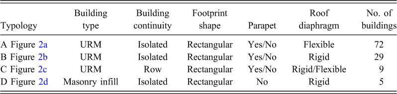
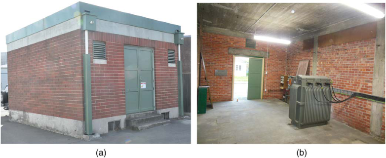
Of the 115 buildings, 110 buildings are clay-brick URM buildings that were erected between 1920 and 1960, and five buildings are clay-brick masonry infill buildings that were constructed after 1950. The majority of the 110 URM substation buildings are constructed of solid double-leaf brick walls, a concrete floor, and a flexible roof diaphragm (76 URM buildings) (Figure 1a), and 34 URM buildings have a rigid roof diaphragm (Figure 1b). Five types of masonry bond patterns were observed: Flemish stretcher bond (59); English garden wall bond (38); Flemish bond (8); running bond (3); and English bond (2). Most of the buildings were observed to contain a concrete perimeter bond beam at ground and eaves levels.
Examples of types of roof diaphragm: (a) Flexible (timber or steel trusses) and (b) rigid (reinforced concrete).
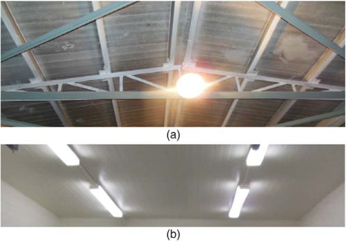
The presence of RC columns in combination with a RC roof diaphragm enabled the masonry infill buildings to be distinguished from the URM buildings, and the presence of air ventilation holes in walls and the use of a running bond pattern for the brickwork indicated whether the masonry infill buildings have cavity brick walls as opposed to solid wall construction. From the collected data, a total of 64 substation buildings were constructed with parapets, and 51 substation buildings have no parapets. The substation buildings were classified into four typologies (i.e., A, B, C, and D) in accordance with the building characteristics presented in Table 1. Figure 2 shows examples for each building typology.
Examples of masonry substation building typologies showing exterior and interior view of each building example: (a) Typology A; (b) typology B; (c) typology C; and (d) typology D.
Architectural Heritage
The substation buildings contributed to the architectural and social history of Christchurch, and some of the substation buildings are listed in the City Plan as Group 4 heritage buildings (Hartrick 2003) due to their age, pleasing appearance, and social significance. The traditional European decorative style that was brought to New Zealand from Victorian England (Hartrick 2003) had great influence on the architectural design of these buildings.
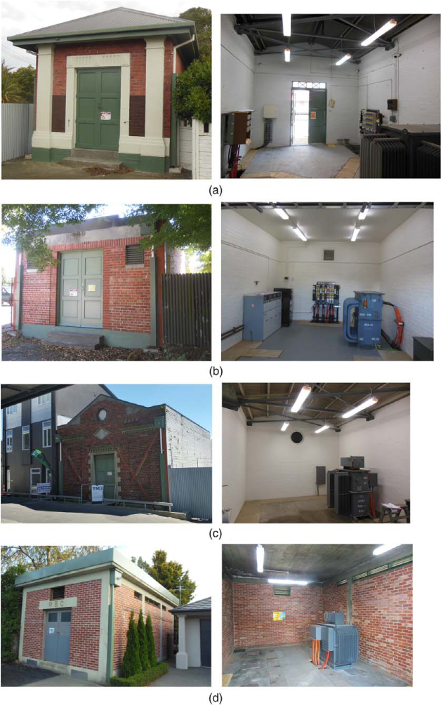
The substation building styles can be grouped into two construction periods: 1920–1940 and post-1940. The three main classical styles for the 1920–1940 building exteriors are: (1) neo-Georgian pavilion (Figure 3a); (2) the guise of the classical temple known as “Temples of Electricity” (Figure 3b); and (3) Art Deco (Figure 3c). A style influenced by Frank Lloyd Wright's Chicago was used for a small number of substations (Figure 3d). While the design of the 1920–1940 buildings focused on decoration and architectural appearance, the design of the post-1940 buildings emphasized seismic resistance. Most of these post-1940 buildings had an additional RC perimeter beam at eaves level. Christchurch experienced a significant loss of heritage following the 2010/2011 Canterbury earthquakes when the Canterbury Earthquake Recovery Authority (CERA) approved at least 104 heritage buildings for demolition (Heather 2011). Consequently, these substation buildings have since gained increased heritage status within the community.
Decorative styles of substation buildings: (a) Neo-Georgian pavilion; (b) Temples of Electricity; (c) Art Deco Moderne; (d) Frank Lloyd Wright's Chicago; and (e) Griffith's modernism (photos taken from Hartrick 2003).
Retrofit Schemes
The Risk and Realities improvement program, initiated in the early 1990s by the Christchurch Engineering Lifelines Group, led to the initiation of an ongoing seismic retrofit program for the substation buildings. This program commenced in 1996 and systematically progressed annually for 15 years (Fenwick and Hoskin 2011) with the objective of reducing exposure to risk from natural hazards. Measures to mitigate earthquake risk were undertaken by adding bracing and steel members at strategic locations within the building structure based upon engineering expertise and experience.
The steel retrofit systems that were added to the substation buildings acted as structural ribs and increased the out-of-plane and in-plane capacity of the substation buildings (Lamb 1997), with the use of steel elements found to be a cost-effective and reversible way to retrofit the substation building (Robinson et al. 2000). The recorded retrofit data were classified into the following groups: 67.8% (78) of the substation buildings received retrofits to both walls and the roof; 22.6% (26) received only wall retrofits; 1.7% (2) received only roof retrofits; 7.8% (9) received no retrofit system.
Walls
Seismic retrofit methods such as steel-braced frames and anchored-steel ties were used to retrofit the walls of the substation buildings. A steel-braced frame consists of vertical and diagonal steel members installed at the corners of the substation buildings either externally, internally, or as a combination of the two options. Substation buildings contain large amounts of electrical equipment, such as switch gears and transformers, and retrofit members were positioned in the most practical locations within the buildings. Priority was given to interior installation of steel members, but members were installed externally when internal access was obstructed. The use of vertical steel equal angles at the building corners with a typical size of 200 × 200 × 10 mm was common, and 150 × 10 mm diagonal steel plates were typically mounted at the entrance and on the rear walls (Figure 4) of the substation building in order to increase both in-plane and out-of-plane wall capacity. Intermediate vertically positioned flat steel plates (typically measuring 100 × 10 mm) were most commonly installed along longitudinal walls in order to improve the wall out-of-plane behavior. Vertical plates effectively acted as tension members to confine the masonry walls by being fixed to the foundation beam and holding down the perimeter bond beam at eaves level.
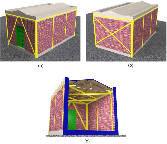
3D views of typical seismic retrofit of a substation building using steel elements: (a) Front view of a substation building showing the external steel retrofit members; (b) rear view of a substation building showing external steel retrofit members; and (c) cross section of retrofitted substation building showing interior retrofit steel elements.
Roofs
A combination of three methods was applied to seismically retrofit the roof elements of the substation buildings: (1) installation of steel bracing elements across a roof diaphragm (Figure 5a); (2) addition of roof diaphragm-to-wall connections (Figure 5b); and (3) mounting of steel plates around the perimeter of a building at eaves level (Figure 5c). Steel bracing was commonly observed in substation buildings with flexible diaphragms (Figure 5a), which provided a load path to transfer lateral loads from roof to walls. In addition, steel brackets were bolted to purlins in order to improve the roof diaphragm-to-wall connections of the substation buildings (Figure 5b). In buildings with rigid diaphragms (Figure 5c), steel plates were commonly installed around the building perimeter at the eaves level.
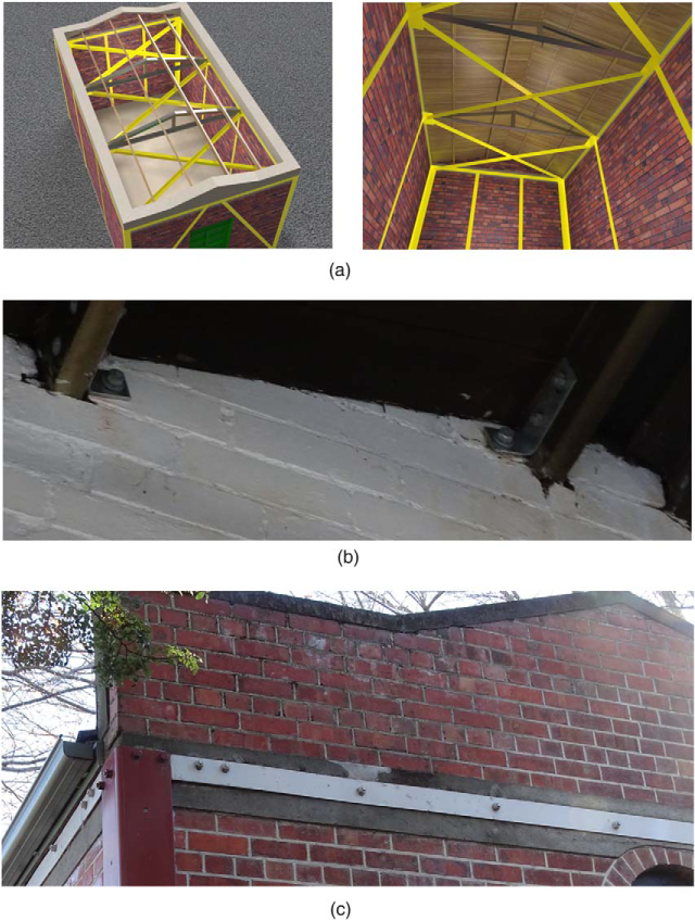
Seismic retrofit at roof level. (a) Flexible diaphragm roof bracing system showing views from above and below; (b) steel brackets bolted at purlin; and (c) steel plates on perimeter concrete beam.
Connections
The connections between the steel-braced frame members and the brick walls utilized 16-mm diameter steel bolts. Four steel bolts were commonly used to fix the vertical steel equal angles at the building corners, and equally spaced steel bolts typically having a spacing of approximately 750 mm were used along the steel plates (Figure 6a and 6b). The connections adopted for vertical intermediate flat steel plates placed across bricks utilized 10-mm diameter mid-bugle head screw that were countersunk into steel members and epoxied into the brickwork approximately 140-mm deep (Figure 6c).
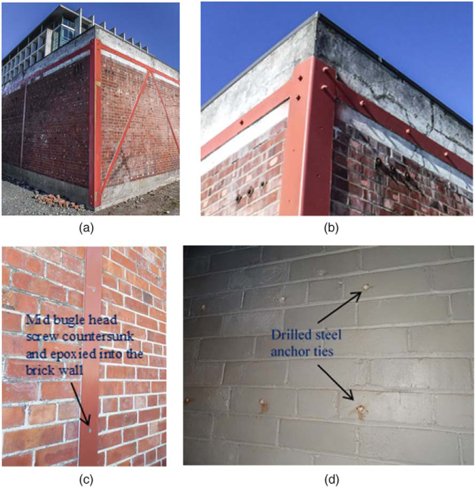
Types of connections used in the retrofitted substation building: (a) Steel element connections; (b) examples of steel angle and place connection with 16 mm steel bolts; (c) vertical flat steel plate connection to wall; and (d) expoxy steel anchor ties.
As discussed previously, most of the masonry walls of the substation buildings were constructed using two masonry leaves, with the leaves generally not adequately interconnected across the collar joint due to the adopted bond pattern. This lack of interconnection posed a potential risk of leaf delamination and premature wall collapse. To address this concern, anchored steel ties were used in some buildings to interconnect the individual masonry leaves and reduce the likelihood of out-of-plane failure. The anchored steel ties were epoxy set in the middle of an individual stretcher unit at spacing of approximately 350 mm both horizontally and vertically. More than 100 steel ties were used for a wall having representative dimensions. Figure 6d shows examples of walls secured with steel anchored ties.
Economic Appraisal
The seismic improvement program entailed a total of N.Z. $6 million (approximately U.S. $4 million) being spent over 15 consecutive years for the seismic retrofits of the substation buildings (an average of N.Z. $400,000 (U.S. $200,000) per year) as a step towards safety improvement of the Christchurch electricity network (Fenwick and Hoskin 2011). The estimated average cost to retrofit each building was approximately N.Z. $21,000 (U.S. $12,000), which included the cost of the retrofit materials and the labor costs. The result of the seismic improvement program is that Orion saved approximately N.Z. $60 million (U.S. $44 million) in direct asset replacement costs following the 2010/2011 Canterbury earthquakes (Orion New Zealand Limited 2012, Kwasinski et al. 2014).
Post-Earthquake Assessment
A post-earthquake assessment team was formed as an emergency response to the 2010/2011 Canterbury earthquakes to examine the substation buildings for safety and structural performance. In general, the building safety evaluations during a state of emergency require three phases of inspections, i.e., overall damage survey, rapid building assessment, and detailed engineering evaluations (NZSEE 2009). The overall damage survey phase was conducted by emergency services personnel and local authority staff, while professional engineers undertook the rapid assessments and detailed engineering evaluations. The detailed engineering evaluations were carried out only if required (NZSEE 2011).
Following the February 22, 2011, earthquake, the damage data for the substation buildings were collected using the overall damage survey and rapid building assessment evaluations. The rapid building assessment was conducted using Rapid Assessment Forms - Level 1 and Level 2 (NZSEE 2009). After the Level 1 rapid assessment, substation buildings were posted with short-term indication placards (i.e., green, yellow, and red). If a building was inspected and no safety issues were identified, the building was assigned a green placard. If there was a safety concern, a yellow placard was assigned, and the building could be entered only for restricted use. A red placard was assigned only if a building was deemed to be no longer safe, and no access was permitted (NZSEE 2009). 97% (112) of the substation buildings were tagged as green, 1% (1) was labeled with a yellow placard, and 2% (2) were marked as red.
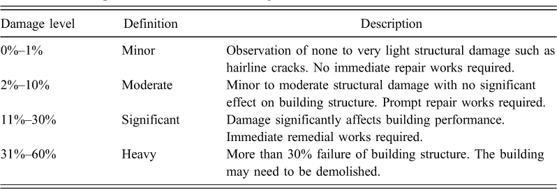
In the Level 2 rapid assessment, a percentage range was used to estimate overall building damage. The Level 2 rapid evaluation can be performed only by professional engineers with a broad experience in technical works. The observed substation buildings were rated with the extent of damage as described in Table 2. Of the 115 masonry substation buildings, 95 buildings were estimated to have minor (0%–1%) damage, 17 buildings experienced moderate (2%–10%) damage, one substation building in Simeon Quay had significant (11%–30%) damage, and two substation buildings, on Wakefield Avenue and St. Andrew Hills, suffered from heavy (31%–60%) damage. Figure 7 shows the location of the assessed substation buildings overlain on a peak ground acceleration (PGA) map, with analysis of observed damage to the substation buildings.
Description of the extent of damage
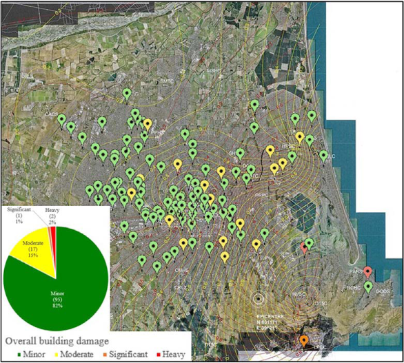
Location and damage levels of substation buildings showing PGA contours from the February 22, 2011, Christchurch earthquake.
The performance of the substation buildings according to the grouped building typologies is shown in Figure 8. Typologies A, B, and D with similar architectural features (one-story, isolated substation buildings with rectangular footprint; see Table 1) showed similar post-earthquake response where the in-plane failure mode was the most dominant for buildings having minor (86) and moderate (17) damage, which is thought to be due to the low axial loads acting on the walls. Buildings with significant (1) and heavy (2) damage experienced wall collapse due to out-of-plane failure, landslide, and boulder damage. There were no cases in which collapse of the parapet was observed, presumably because most parapets were constructed of reinforced concrete and had low aspect ratios, although one parapet that was constructed of clay bricks was slightly displaced as a result of earthquake-induced shaking (Figure 9). All row substation buildings (typology C) that exhibited minor damage (eight out of nine buildings in this typology) were situated at the extremity of a row.
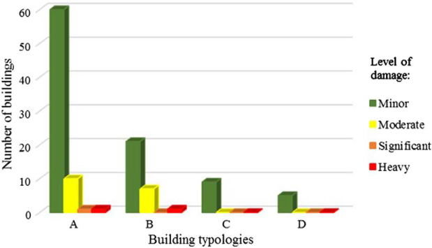
Damage level corresponding to building typologies.
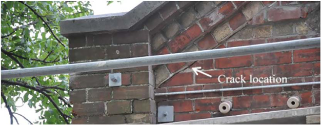
Displaced clay bricks parapet.
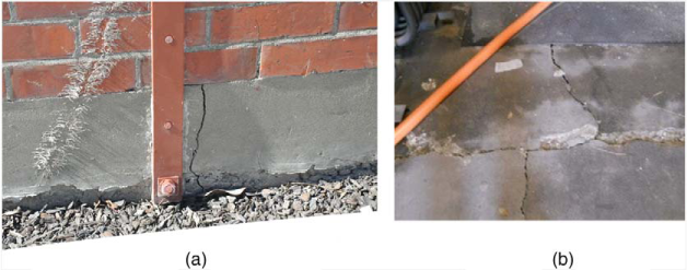
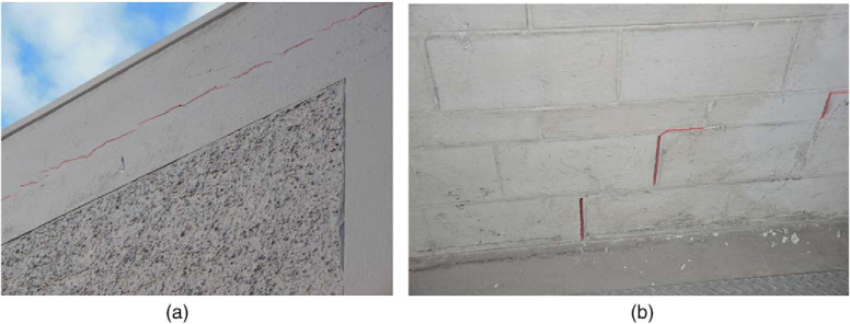
Buildings with a damage estimation of 0%–1% represented buildings with none to very minor damage (Figure 10), and these buildings could be immediately occupied, as no safety concerns were highlighted. 62% (59) of the 95 buildings with minor damage were labeled with green placards, G1 (no immediate further investigation required), while 38% (36) were tagged with G2 (repair work required).
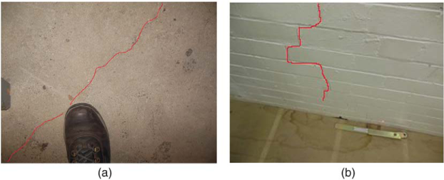
Observations of minor damage: (a) Hairline cracking on floor and (b) hairline cracking on masonry wall.
Buildings with minor to moderate damage had approximately 2%–10% estimated damage (Figure 11) and were labeled with green placards (3 and 14 buildings with G1 and G2 labels, respectively). Most of the buildings assessed with this damage level experienced ground movement or settlement that caused foundation settlement and floor damage, and re-levelling works had to be performed to buildings with noticeable foundation movements. Repair works for damaged or displaced parapets included the provision of addition steel rods to restrain the parapet from collapse.
Examples of moderate damage due to ground settlement: (a) Cracking on concrete foundation and (b) cracking on floor.
A substation building in Simeon Quay, which was located at the base of a clay cliff, suffered significant damage due to landslide from a nearby cliff face (Figure 12). The landslide damaged the rear part of the building and caused significant damage to the roof. The strengthened walls performed well with only minor damage being observed, and the substation remained operational.
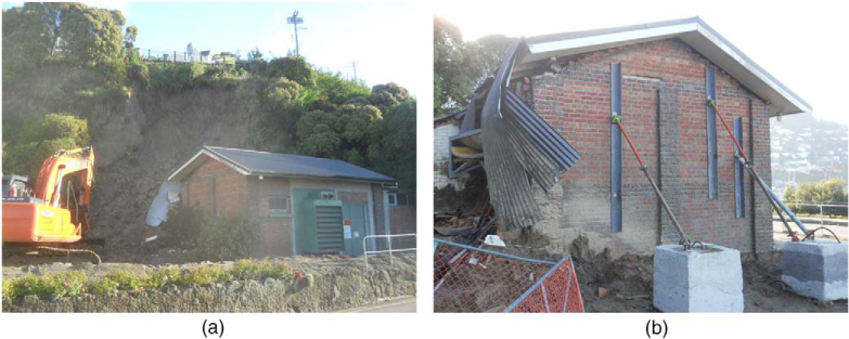
Significant damage to Simeon Quay substation building: (a) Landslide caused damage to the rear of Simeon Quay substation and (b) precautionary supports added to the Simeon Quay substation after severe landslide.
Two substation buildings in Wakefield Avenue and St. Andrew Hills suffered heavy (31%–60%) damage (Figure 13). Both buildings were located close to the epicentre of the February 22, 2011, earthquake and were subjected to an estimated PGA of 1.2 g. The damage to the Wakefield Avenue substation buildings was attributed to boulder damage (Figure 13a) that caused about 50% of the substation building to collapse, although the front portion of the building was able to remain intact due to the seismic retrofit. The substation building was decommissioned and bypassed as a result of the damage. The St. Andrew Hills substation building suffered diagonal shear failures and partial collapse of the north and east URM walls due to significant earthquake shaking (Figure 13b). Despite the damage, the seismic retrofit system continued to support the roof (Figure 13c), and the transformer remained operational while demolition work was undertaken. The building has since been demolished and replaced with a lightweight steel kiosk.
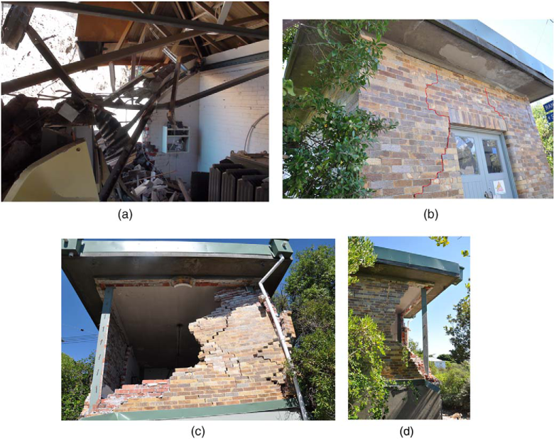
Heavy damage of substation buildings: (a) Damage due to boulder roll; (b) in-plane failure caused large diagonal shear crack of piers; (c) out-of plane failure of brick wall due to significant shacking; and (d) the vertical steel elements prevented full collapse.
Substation buildings that had both retrofitted walls and retrofitted roofs performed satisfactorily in the earthquake sequence, and a similar observation was drawn for substation buildings that had only retrofitted roofs or retrofitted walls. Overall, no significant differences in the proportions of damage were observed among the three sets of retrofit classifications (see Figure 14), although the retrofit of both walls and roofs is understood to provide the greatest seismic resilience to the substation buildings at a minor additional overall cost. Such cost-effective, simple, and practical seismic retrofit techniques could be adopted for other building typologies where the resulting somewhat ponderous appearance of the building is not of concern.
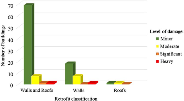
Level of damage corresponding to retrofit classification.
Case Study: Buildings with No Retrofit
Of the 115 substation buildings, nine substations had no seismic retrofit system (Figure 15), with three of the un-retrofitted buildings being identified as constructed of masonry infill with a rigid diaphragm (Figure 15b) and six being URM buildings with a flexible diaphragm (2) or a rigid diaphragm (4). The three masonry infill buildings and the two URM buildings with flexible diaphragms performed well and sustained only minor damage. Of the four URM buildings with rigid diaphragms, two sustained minor damage and two sustained moderate damage (Figure 16). No out-of-plane failure modes were observed for these un-retrofitted buildings, due mainly to the presence of an RC perimeter beam that provided good load distribution. Most of the observed damage was associated with in-plane related cracking.
Characteristics of substation buildings without retrofit: (a) Single story, small openings, and RC perimeter beam at roof and beam level; and (b) Masonry infill structure with RC roof diaphragm and rectangular footprint.
Examples of minor and moderate damage of buildings with no retrofit: (a) Cracking between parapet and bond beam and (b) diagonal shear crack at wall.
The date of construction and the location of buildings were parameters that influenced the good performance of the un-retrofitted substation buildings. All of the un-retrofitted substation buildings were constructed post-1940, and their designs incorporated earthquake-resilient details, with a RC perimeter beam being incorporated into each design. The un-retrofitted substation buildings were subjected to relatively low PGAs (0.2 g–0.3 g) in the February 22, 2011, event because they were located far from the earthquake epicenter. In comparison, the retrofitted substation buildings that suffered significant and heavy damage (Figures 12 and 13) were subjected to PGAs of up to 1.2 g during the February 22, 2011, earthquake and were located closer to the earthquake epicenter.
Case Study: Retrofitted versus Un-Retrofitted Urm Building
The benefit of the retrofit system can clearly be observed in a building shown in Figure 17, which illustrates a shared building consisting of two separate tenancy portions. One building portion was occupied by Orion and was seismically retrofitted, while the other building portion immediately adjacent (not occupied by Orion) was not retrofitted and experienced severe damage during the February 22, 2011, earthquake. Large ground deformation due to earthquake shaking caused moderate (Figure 17c) and significant damage (Figure 17b) to the retrofitted and un-retrofitted URM buildings, respectively. The steel elements installed on the retrofitted building minimized the building damage and resulted in only minor re-leveling repair works. The un-retrofitted buildings needed major repair works due to severe damage to the concrete floor and damage to the brick masonry walls of the building.
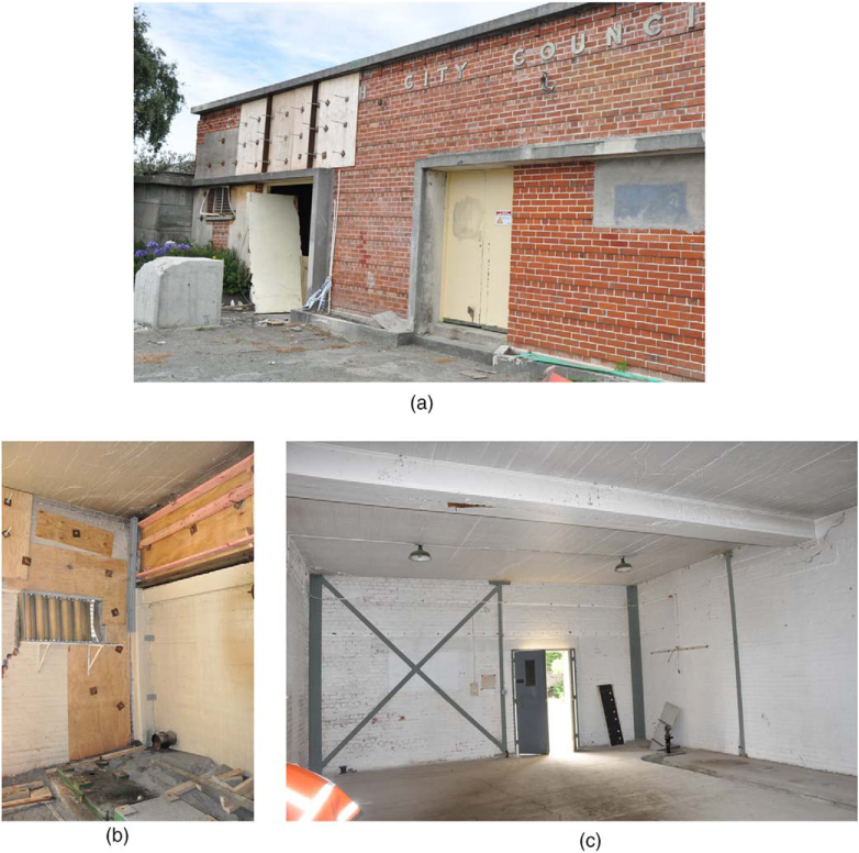
Example of retrofitted versus un-retrofitted URM buildings. (a) Performance of retrofitted (right) and un-retrofitted (left) URM building portions following the 22 February 2011 Earthquake. Note: The Extensive use of of plywood sheets with plate anchors to secure damaged masonry. (b) Severe damage to un-retrofitted building portion. (c) Internal view of retrofitted building portion showing structural elements and good seismic performance.
Summary and Conclusions
The overall performance of 115 clay-brick masonry substation buildings in the 2010/2011 Canterbury earthquakes was evaluated. This evaluation was based on multidisciplinary criteria that included the structural seismic performance of the substation buildings as well as social (heritage) and economic aspects of the retrofits. The typical characteristics of the substation buildings and the details of the retrofit schemes have been thoroughly discussed. Of the 115 studied buildings, 95 (82%) and 17 (15%) were rated as having minor and moderate damage, respectively, and only three substation buildings were classified as having significant or heavy damage. The provided steel-bracing system successfully restrained the substation buildings, thereby preserving these heritage buildings and minimizing the effects of power outages after the Canterbury earthquakes. The retrofit system was a financial success, with cost savings to Orion due to direct asset replacement of up to approximately N.Z. $60 million (U.S. $44 million) and the benefit to the Christchurch community of having the electricity network operating during the earthquake recovery being extensive. These substation buildings are now one of the most distinct remaining examples of Christchurch's architectural heritage after the demolition of most unreinforced masonry buildings in Christchurch following the Canterbury earthquakes (Moon et al. 2014).
Footnotes
Acknowledgments
The authors gratefully acknowledge the assistance of John O'Donnell, chief operating officer of Orion New Zealand Limited, and Eoin Richdale, director of Richdale Builders Limited. The financial support of the QuakeCoRE, a New Zealand Tertiary Education Commission-funded Centre, is thankfully acknowledged. This is QuakeCoRE Publication Number 0056.