
Abstract
Recent earthquakes in Pakistan demonstrated that the region is highly seismic. Masonry buildings constructed with stones, concrete blocks, and fired-clay bricks and concrete buildings were damaged during the 8 October 2005 Kashmir earthquake. This paper presents the seismic behavior of reinforced concrete and masonry buildings in northern part of the North-West Frontier Province (NWFP) and Kashmir during the earthquake. Most of the buildings were observed to be nonengineered or semi-engineered. The paper presents an overview of the 1937 Quetta building code and the 1986 and 2007 building codes of Pakistan. Lessons learned during the earthquake are also presented.
Introduction
On 8 October 2005, an earthquake of magnitude Mw =7.6 struck northeastern part of the North-West Frontier Province (NWFP) of Pakistan and southwestern part of Kashmir. It caused extensive damage to manmade infrastructure over an area of 30,000 sq. km in the districts of Manshera, Battagram, Abbottabad, and Shangla in NWFP, and Muzaffarabad, Bagh, Garhi Dubata, and Neelam in Azad Jamu and Kashmir (Figure 1). Balakot and Muzaffarad were the worst-hit cities because of their proximity to the epicenter of the earthquake. Masonry buildings constructed with stones, concrete blocks, and fired-clay bricks and concrete buildings were partially or severely damaged. The Kashmir earthquake resulted in more than 73,000 casualties, while 80,000 people were injured, and more than 3 million people were left homeless (ADB-WB 2005).
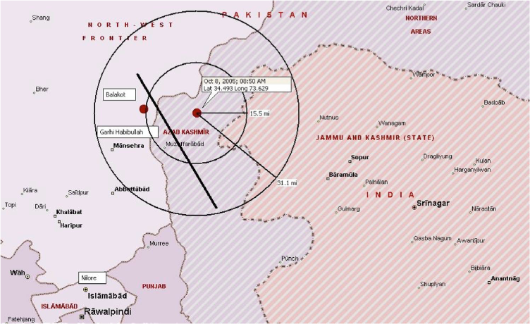
Earthquake-affected areas within radii of 25 and 50 km from the epicenter (map shows the cities of Muzaffarabad and Balakot, which were severely affected by the Kashmir earthquake, and Abbottabad, Murree and Nilore, where earthquake ground motions have been recorded.)
The Kashmir earthquake occurred on 8:50 a.m. local time (3:50 UTC). The epicenter was estimated at 34.49° N and 73.63° E and located about 10 km (6.2 miles) NE of Muzzaffarabad and 90 km north of Islamabad. The epicenter was estimated at a depth of 26 km (16.2 miles) (USGS 2005). The direction of the fault was estimated to be from N27E to N30E. The length of rupture was about 75 km (46.6 miles). The fault plane dips about 29° and the mechanism is mostly thrust. The average slip was observed to be between 2 to 5 meters (Bendick 2007, Jayangondaperumal and Thakur 2007).
The main shock of the Kashmir earthquake and the epicentral area lie in the Kashmir-Hazara syntaxis region, south of Himalaya (Jayangondaperumal and Thakur 2007) as indicated in Figure 2. The surface trace of the fault extends from Balakot to Muzaffarabad and further SE for a length of 52 km (32.3 miles) (Jayangondaperumal and Thakur 2007).
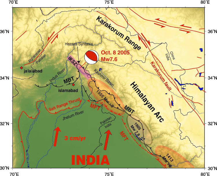
Tectonic settings of the Kashmir earthquake. Major active faults are indicated in red. Dashed lines indicate approximate locations of the blind thrust faults. MBT: Main Boundary Thrust, MFT: Main Frontal Thrust, IKSZ: Indus-Kohistan Seismic Zone. (Courtesy of Jean-Philippe Avouac 2006)
In this paper, a brief overview of regional tectonic settings and seismicity is provided. Seismic provisions of the country building codes of 1937, 1986, and 2007 are presented. The performance of buildings during the Kashmir earthquake is discussed in detail. On the basis of the building code, the tectonic setting and seismicity of the region, and lessons learned from the earthquake, conclusions are provided to mitigate hazards in the future. A brief discussion of the postearthquake research work is also presented.
Seismicity of the Region
Pakistan is situated in a region of high seismicity; two tectonic plates have their boundaries in this region. The Indian plate, moving northward at a rate of about 30 mm (1.18 in.) per year, is subducting underneath the Eurasian plate, resulting in the high peaks of Himalaya, Karakoram, Pamir, Hindu-Kush and Tibetan Plateau. The northward compressive movement of Indian plate has also resulted in the multiple thrust faults (Figure 2) of the Eurasian Plate, which consequently cause many earthquakes in the region. The main boundary thrust (MBT), main mantle thrust (MMT), main Karakorum thrust (MKT) are examples of thrust faults generated in this process.
Significant earthquakes that have occurred in the thrust zone are the 1555 Srinagar earthquake of Mw >6.7, 1897 Shilong earthquake of Mw =8, 1885 Kashmir earthquake of Mw =6.3, 1905 Kangra earthquake of Mw =7.8 (Bilham 2004), and 1974 Patten earthquake. The Shilong, Kangara, and Patten earthquakes resulted in the loss of 1,542, 20,000, and 6,300 lives, respectively. The recent earthquake clearly demonstrates that the region has the potential for producing major earthquakes. It is considered that only a small percentage of the stored energy in the active tectonic is released due to the Kashmir earthquake and is considered moderate in the context of earthquake-generating potential of the region. There is a possibility for the repetition of earthquake of magnitude Mw >8 in the region affected by the Kashmir earthquake (Avouac 2006).
Strong Ground Motion
The strong ground motion generated by the Kashmir earthquake was recorded at three locations—Abbottabad, Murree and Nilore—by a network operated by Pakistan Atomic Energy Commission under the Micro-Seismic Studies Program (MSSP). The closest instrument was located in Abbotabad, a city 52 km from epicenter. The instrument is installed in a small room constructed on an alluvial deposit (Maqsood and Schwarz 2008). The components of the accelerogram of the main shock recorded at Abbottabad are reproduced in Figure 3.
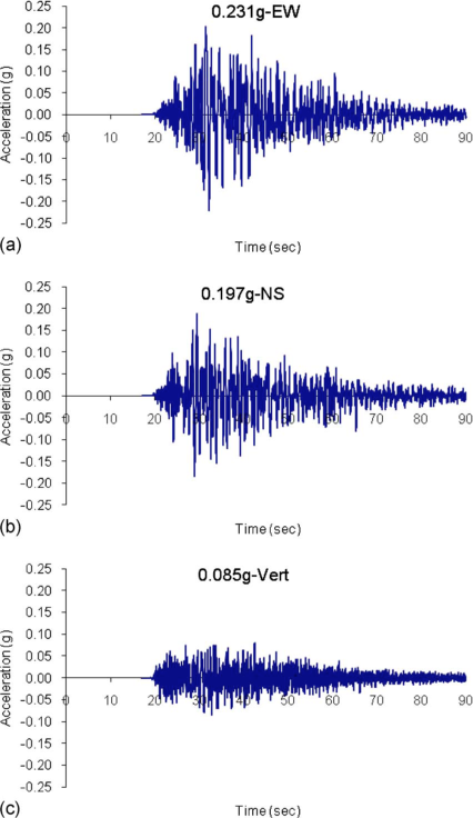
(a) East-west component (PGA=0.231 g), and (b) North-south component (PGA =0.197 g), and (b) Vertical component (PGA=0.085 g) of the accelerogram recorded at Abbottabad. (Courtesy of Pakistan Atomic Energy Commission 2005)
The 5% elastic response spectra for the east-west, north-south, and vertical components of the Abbottabad accelerogram are shown in Figure 4. The spectrum of the east-west component shows high amplification over a range from 0.5 to 1.5 sec with the highest amplification of about 4 sec. This high amplification could put high demand on medium to high rise buildings. If the design spectra of UBC 97, which is now part of the 2007 Building Code of Pakistan, is plotted for Abbotabad, corresponding to zone 3 and soil profile D, the flat portion of the spectra renders spectral acceleration values of 0.9 g (2.5×0.36 g =0.9 g) which is very close to the value given by the computed response spectra.
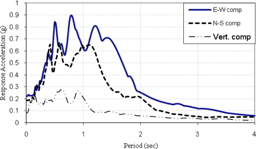
Elastic response spectra (with 5% damping) for east-west, north-south and vertical components of accelerogram recorded at Abbottabad.
As mentioned above, no strong motion data could be recorded near source, except at few locations away from the epicenter. Peak ground acceleration (PGA) values could be generated at different locations by using recorded data and attenuation relationships. The attenuation relationship could be selected based on source mechanism, magnitude, geology and local soil conditions. Keeping in view these criteria, Durrani et al. (2005) selected Ambraseys et al. (2005) attenuation relationship and utilized it to obtain estimates of the PGA values (PGA=0.237 for soft soil and 0.194 for stiff soil) for Abbottabad.
Building Codes in Pakistan
Although frequent earthquakes of moderate magnitudes have occurred in Pakistan, but no serious efforts have been made regarding the assessment of seismic hazard and the development and enforcement of a national seismic building code. Although city or regional bylaws are available for the regulation of architectural plans, they have no requirements regarding the structural analysis, design, and construction of buildings and other structures. In the absence of a national building code, foreign codes such as the American Concrete Institute (ACI) Code and Uniform Building Code (UBC) have been used.
The Quetta earthquake of 30 May 1935 flattened the city of Quetta and resulted in 60,000 casualties. The country's first building code, known as Quetta Building Code (1937), was developed and enforced in 1937 by the British Government within the municipal limits of Quetta city. Unreinforced masonry buildings were forbidden. Eight modular building designs were proposed for use in the different parts of Quetta. The first modular type, consisting of steel frame with reinforced concrete floor and reinforced masonry infill wall panels, was allowed to be used for buildings up to two stories high with a maximum height of 8.2 m (27 ft). Types 2 and 3 were reinforced brick masonry single-story buildings with reinforced concrete floors. Type 4 had a timber frame with infill panels of brick or other materials. Types 5 and 6 were also of timber frame but differ in other aspects from Type 4. Type 7 was of timber or steel frame with corrugated iron-sheet roofing, and Type 8 was rough ballie framework with Pise work. The first three types were required to be designed to resist lateral forces equal to 12.5% of the weight of the structure above the said horizontal plane of the building. It was also made mandatory for the first time to provide reinforced concrete bands 240 mm (9.5 in) in thickness with two 16 mm (5/8 in.) diameter steel bars at plinth, lintel, and roof levels (in case the roof is not reinforced concrete) in the masonry buildings. The minimum thickness of the brick masonry wall was specified to be 350 mm (13.5 in) and should be laid in 1:3 cement-sand mortar. Two 16 mm (5/8 in) diameter bars were required to be provided at all corners, at door and window openings and at horizontal intervals of 1.5 m (5 ft). Guidelines were also provided for connecting transverse masonry walls. Limits on the dimensions of building, height of parapet walls, chimneys and span of balconies were imposed. Specifications of building materials were also provided in the code.
The Quetta building code was developed on the basis of observed behavior of buildings and the engineering judgment of structural engineers. There are many similarities between the seismic and material provisions of this code and those of modern building codes (e.g., Eurocodes 6 and 8). Buildings constructed in Quetta in compliance with this code were put to the test during an earthquake of magnitude 7.1 in September 1941, and they performed extremely well (Jain and Nigan 2000). The Quetta building code was enforced at a local level and not extended to other parts of the country.
In 1986, Pakistan Building Code (1986) was developed by the Federal Ministry of Housing and Works. The seismic provisions of this code were based on the 1982 edition of the Uniform Building Code. The seismic zoning map of Pakistan of the 1986 Pakistani Building Code is shown in Figure 5. The map was based on the Geophysical Centre of Quetta's instrumental macro-earthquake data for the period of 1905 to 1979. The map could be applied for all structures except nuclear structures, large dams, and structures containing highly toxic chemicals. The area of Pakistan was divided into five seismic zones, i.e., Zone 0 through Zone 4. Zone 0 represents areas with negligible hazard (damage) while Zone 4 represents areas with significant seismic hazard (major damage corresponding to intensity VII and higher on the 1931 MMI scale). Almost all the areas affected by the Kashmir earthquake and Islamabad were placed in Zone 2 of the 1986 Pakistan Building Code. However, the Kashmir earthquake produced earthquake intensities of VIII and higher in all major cities of the affected region.
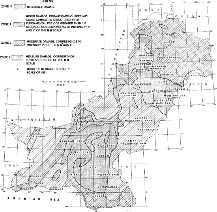
Seismic zoning map of Pakistan (PBC 1986).
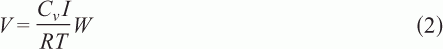
The code required all structures to be designed for the base shear, V, given by the following equation:

The 1986 Pakistani Building Code was an incomplete document as it lacked seismic provisions for concrete, steel, and masonry buildings. The code was not officially adopted by the federal, provincial, or city governments. The absence of a seismic building code resulted in substandard and deficient construction.
The Earthquake Rehabilitation and Reconstruction Authority (ERRA) was constituted immediately after the Kashmir earthquake by the federal government, with a mandate to regularize the design and construction of government and public buildings in the earthquake affected areas. Buildings were required to be designed in accordance with the provisions of UBC 97 until the development and implementation of a Pakistan Building Code.
The 2007 edition of Pakistan Building Code (2007), containing detailed seismic design parameters and criteria for seismic resistant design of buildings, was developed after the 2005 Kashmir earthquake. The new code is mostly based on the 1997 edition of the Uniform Building Code (1997), American Concrete Institute Code (ACI 2005), ANSI/AISC 341-05, and ASCE (1993). The code has been adopted by Pakistan Engineering Council (PEC) and other relevant federal and provincial departments.
An updated seismic hazard map is included in this code (Figure 6). All the buildings are required to be designed for a level of earthquake ground motion that has a 10% probability of exceedance in 50 years. The area of Pakistan has been divided into five zones (1, 2A, 2B, 3, and 4) based on the peak ground acceleration. Balakot and Muzaffarabad are placed in seismic Zone 4, while Abbottabad and Islamabad have been assigned to Zone 3 and Zone 2B, respectively.
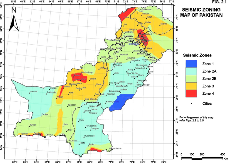
Seismic zoning map of Pakistan (PBC 2007).
The design base shear, V, is given by the following formula:
Upper and lower limits have been imposed on the design base shear. Near source effects have been considered in the determination of design base shear. In the recent version of the code, modifications have been made in the provisions regarding masonry structures involving requirements for minimum compressive strength of masonry units (8.25 MPa (1200 psi) for solid fired-clay bricks and 5.5 MPa (800 psi) for solid/hollow concrete blocks), mix proportions and compressive strength of mortar (4.10 MPa (600 psi)), and compressive strength of masonry. Limitations on the number and height of stories and minimum thickness of walls have also been specified. Because of the poor performance of stone masonry buildings in the Kashmir earthquake, use of rubble stone masonry is prohibited. In order to increase the integrity and to ensure better performance of unreinforced masonry buildings, use of reinforced concrete bond beams has been made mandatory at the plinth, door, and roof levels. Confined masonry has been introduced and detailed provisions have been specified in the Code keeping in view its good performance in other parts of the world.
The chapter on masonry buildings lack explicit analysis and design procedures for masonry buildings. The response modification factors which represent the energy dissipation capacity of the different masonry building systems have not been provided. Since Pakistan building code 2007 is a modified form of modern seismic building codes, extensive indigenous research is required to calibrate the provisions of the Code. Research is in progress to evaluate the performance of single- and double-story stone masonry buildings with different levels of confinement (Ali 2009), and shake-table testing of model unreinforced (Zakir 2009) and confined (Amjad 2009) brick masonry buildings is underway to determine the seismic performance and response modification factors for the respective class of buildings.
Design and Construction Practices Prevalent in Pakistan
Stone, concrete block, and solid fired-clay masonry units have been traditionally used as materials for the construction of single- and double-story buildings in Pakistan. Most masonry buildings were constructed with unreinforced masonry and were nonengineered, as explicit verifications of adequate resistance to seismic lateral forces were usually not carried out.
Description of Building Types
Adobe buildings have been the most common type of construction in the rural areas. In this type of construction, load-bearing walls, 400–450 mm (15.5–18.0 in) thick, were constructed from adobe brick or mud. The walls resisted high vertical loads of roof having 200–300 mm (8–12 in) of mud provided for insulation purposes. There was no proper connection between the orthogonal walls or between walls and roof. The heavy roof with weak walls made the building vulnerable to even low seismic excitations.
Single- and double-story unreinforced stone masonry buildings were the second most common form of building type adopted both in the urban and rural areas. Stone masonry up to three stories high could be seen in the cities of Abbottabad and Muzaffarabad. Building walls, usually 400–450 mm (15.5–18.0 in) thick, were constructed with mud or weak cements-sand (1:8 or 1:10) mortar. Most of the buildings were constructed of rubble stone masonry. Orthogonal walls and walls and floor were not properly connected. These buildings usually have 150 mm (6 in.) thick reinforced concrete floor and roof and 3.5–4.25 m (12–14 ft) story height. Wooden and steel truss with galvanized iron (GI) sheet were also used as the roofing system. Orthogonal walls and walls and floor were not properly connected. The corners and junctions of walls were liable to failure because of the lack of proper connection. The buildings were vulnerable to out-of-plane failure due to inclined roof and failure of external veneer because no band beams at roof level and through stones were provided.
Another common type of building was single- or double-story unreinforced concrete block masonry building. Single-leaf block masonry walls, usually 150–200 mm (6–8 in.) thick, were normally constructed with a weak cement-sand mortar (1:8). In these buildings, reinforced concrete slabs, usually 125–150 mm (5–6 in.) thick, were provided as floors and roofs. Typical story height was 3.0–3.5 m (10–11.5 ft). Concrete blocks were manufactured from cement, sand, and crushed stone in a semi-automatic machine. It was a common practice to produce 80–100 blocks from one bag of cement with a mix proportion of 1:6:12 or 1:8:14. The average compressive strength of concrete blocks collected from the earthquake affected area, immediately after the earthquake, was found to be 0.75 MPa (110 psi). Extremely low quality of materials (block and mortar) made the unreinforced block masonry more vulnerable to ground motion.
Unreinforced brick masonry system has been utilized for one- to three-story buildings. Double-leaf load-bearing walls were usually 230 mm (9 in.) thick, and the story height was typically 3.0–3.5 m (10–11.5 ft). However, no special arrangements were made for connecting orthogonal walls. The walls laid in English bond gave good connectivity. The workmanship in the brick masonry was comparatively better than the other types of masonry. Cement-sand mortar in the proportion of 1:6 or 1:8 was used. The floors and roofs were usually 125–150 mm (5–6 in.) thick reinforced concrete slab. The bricks were generally of good quality having an average compressive strength of 14.5 MPa (2100 psi).
Concrete-framed structures from two to five stories, on the other hand, were semi-engineered, in the sense that they were designed only for gravity loads. Structural designers used to model and design these buildings as skeletal structures ignoring the presence of masonry infill walls constructed from fired-clay bricks or concrete blocks. No separation or mechanical connection is provided at the interface of the unreinforced masonry infill walls and the reinforced concrete columns or beams.
Ground floors of commercial buildings are mostly used as shops, with wide openings in the front side and brick infill walls on the remaining three sides. Wide open spaces encompassing many bays are also common in these buildings. The upper floors of these buildings are used either as residential units or as stores for keeping goods for shops with a load in excess of 4.8 kN/m2 (100 lbs/ft2). This type of multiple occupancy of a single building, where ground floors have more open spaces compared to upper floors, and heavily loaded upper floors make the buildings more vulnerable to earthquake ground motions. The vulnerability of the RC buildings was also increased with the use of poor quality of concrete and poor detailing practice. Concrete mix was typically proportioned as 1:2:4 (cement-sand-coarse aggregate) with no control on the water-to-cement ratio. Vibrator for the compaction of structural concrete was seldom used.
The statistical overview of building stock in the earthquake-affected rural and urban areas is given in Table 1. The overall percentage distribution of building stock is also provided.
Statistical overview of buildings in the affected area
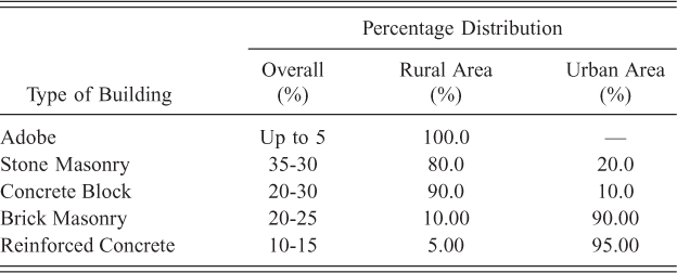
Figure 7 shows typical plans of brick and block masonry residential buildings adopted in the areas affected by the Kashmir earthquake. The rooms are provided in a single row or in L- or U-shaped arrangements. A veranda, supported by slender columns, is provided in front of the rooms (Figure 17). Building plans were being developed with no adherence to the guidelines for ensuring reliable seismic behavior resulting in buildings with much smaller strength and stiffness in one direction than the other. Vertical and plan irregularities were common in the buildings. Walls are not symmetric in the orthogonal direction. Symmetry was also not followed in the vertical direction for the walls and openings. Construction of unreinforced brick or block masonry on the existing stone masonry walls was also observed in Muzaffarabad.
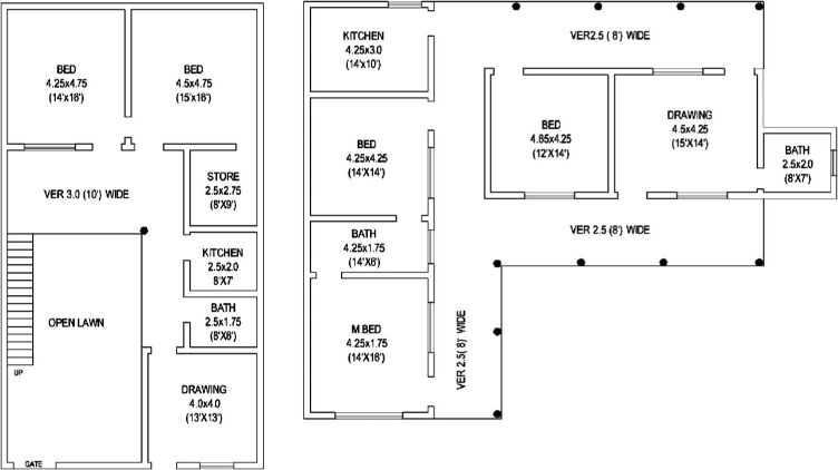
Plans typically used for residential masonry buildings.
Effect of Earthquakes on Built Environment
The buildings which were partially or fully damaged by this earthquake were estimated at about 450,000 (ADB-WB 2005) and includes buildings constructed with reinforced concrete and unreinforced stone, concrete block, and brick masonry. Buildings constructed with rubble stone masonry suffered the heaviest damage followed by concrete block masonry (Naseer et al. 2005). Almost 95% of the stone masonry buildings in the earthquake-affected region were severely damaged. Damaged block masonry buildings were estimated to be 60–65%. Brick masonry buildings performed comparatively better with only 5% buildings collapsed and 35% were severely damaged. In reinforced concrete buildings, 50–60% was partially or severely damaged.
In the following sections, damages to both reinforced and concrete buildings and their causes are discussed.
Reinforced Concrete Buildings
Reinforced concrete buildings (RC) could be categorized as semi-engineered because they were usually designed for gravity loads only. These types of buildings also suffered heavy damages in the cities of Abbottabad, Manshera, Batagram, Balakot, and Muzaffarabad. The causes of failure could be attributed to a combination of the poor design and construction practices. Lack of proper confinement in columns, insufficient lap length, strong beam-weak column, short column, and soft story were among the poor design practices observed from the damaged buildings. Poor construction practices, including improper compaction of concrete, construction joint, and notching of concrete column for door and window lintel beam, were also observed to be responsible for damages to concrete buildings.
Poor Detailing Practice
Because of the absence of a national seismic building code and its effective enforcement, buildings were poorly designed and detailed. This can be observed from the damaged buildings in Figures 8 and 9. This includes the lack of proper confinement in the column, insufficient lap splice length and its location in the beam and column, use of plain bars, and stirrups and ties with improper hooks. The ties in the column were uniformly provided at a spacing of 300 mm (12 in.) or more, irrespective of the structural demand or code requirements; according to UBC 97 code, for moment resisting frames in seismic Zones 3 and 4, the maximum tie spacing should be the minimum of either one-quarter minimum member dimension or 100 mm (4 in). The lap splice in the columns, 240–720 mm (6–18 in.) in length, was normally provided at the base of the floor. However, according to UBC 97, the lap splice for concrete frames located in seismic Zones 3 and 4 should be provided within the center half of the column and should be proportioned as tension splice. Because of the lack of confinement at the highly stressed zones (near beam-column joint) and insufficient lap length, stresses in the reinforcing bars could not be developed which consequently resulted in the failure. These detailing deficiencies have been observed in almost 90–95% of reinforced concrete buildings in the cities of Abbottabad, Mansehra, Balakot, and Muzaffarabad.
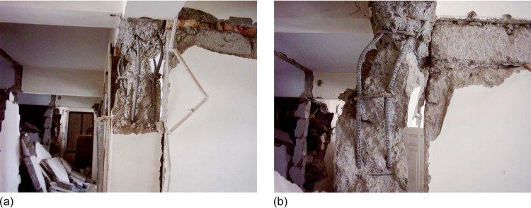
Failure due to insufficient confinement of concrete at beam-column joint. (Ties were provided at 12 in. spacing in 9 in. ×18 in. concrete column of a commercial building in Muzaffarabad).
Failure of building columns in Abbottabad due to insufficient lap lengths.
Strong Beam-Weak Column
The least dimension of the column was commonly selected as equal to the dimension of the infill masonry unit (230 mm (9 in.) with fired clay brick and 203 mm (8 in.) with concrete block) so that the column would not be projected outward from the wall. The desire to have maximum space in the horizontal direction usually resulted in fewer columns with smaller cross sections. Also, most of the concrete structures were designed for gravity loads only. Probably because of these reasons, buildings with strong beams and weak columns were constructed. The weak nonductile columns suffered damage because of the lateral seismic demand, which could further be aggravated by axial forces from the elastic beams. The example of buildings damaged having strong beams and weak columns are illustrated in Figure 10.
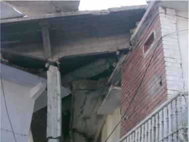
Collapsed building due to strong beams and weak columns.
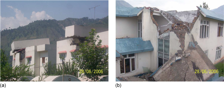
Soft-Story Effect
The soft-story effect was more evident in commercial buildings than residential because the ground floor is typically has more open spaces for shops and parking vehicles. This type of structural deficiency puts more deformation demand on the flexible lower story columns and because of the insufficient energy dissipation capacity of the columns, it resulted in the failure of lower stories. The buildings damaged by soft-story mechanism could be seen in the cities of Abbottabad, Manshera, Batagram, Balakot, and Muzaffarabad as shown in Figure 11.
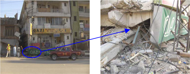
Building failure due to soft story.
Construction/Workmanship Problem
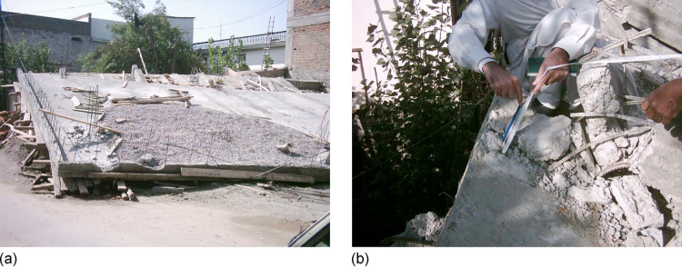
The construction-related problems, including improper compaction of concrete and improper treatment of construction joints, could not be ruled out as causes of failure in reinforced concrete buildings. Figure 12 shows poorly compacted concrete in columns. Vibrators are rarely used for the compaction of concrete in columns. The concrete strength estimated by Schmidt hammer test during the reconnaissance survey in both private and public buildings rarely exceeded 13.75 MPa (2000 psi).
Poorly compacted column concrete.
Notches were formed (Figure 13) in the concrete columns for accommodating lintel beam over door and window opening, making the concrete section more vulnerable to damage. Improper treatment of construction joint resulting in sliding failure was also observed in Muzaffarabad and shown in Figure 14.
Reduction in column cross section due to notch created to accommodate lintel beam.

Damage at construction joint in Boys Hostel, Muzaffarabad.
Masonry Buildings
In-Plane Damages
Diagonal Shear Failure of Wall Piers
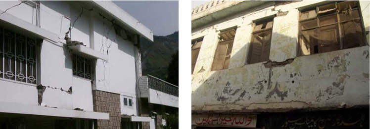
For heavily loaded masonry wall piers with low aspect ratios, in-plane shear forces of the wall causes diagonal shear failure in the form of X-cracks. This type of failure does not endanger the gravity load-carrying capacity of a wall unless cracking becomes severe or out-of-plane movement takes place. The diagonal shear failure is also associated with in-plane shear sliding of the masonry wall. Figure 15 shows building walls cracked in diagonal shear during the Kashmir earthquake. This type of failure could be seen throughout the affected area.
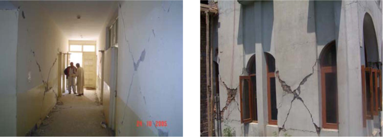
Diagonal shear failures of masonry wall piers.
Flexure Failure of Pier
Piers with large aspect ratios fail in flexure under alternating bending moments caused by the cyclic nature of the seismic forces. This type of failure manifests itself in the form of horizontal cracks at the top and bottom ends of the pier. The cracked pier moves as a rigid body having no lateral-load resisting capacity (Bruneau 1994). Figure 16 shows the flexure failures of wall piers in residential buildings.
Flexural failures of masonry wall piers.
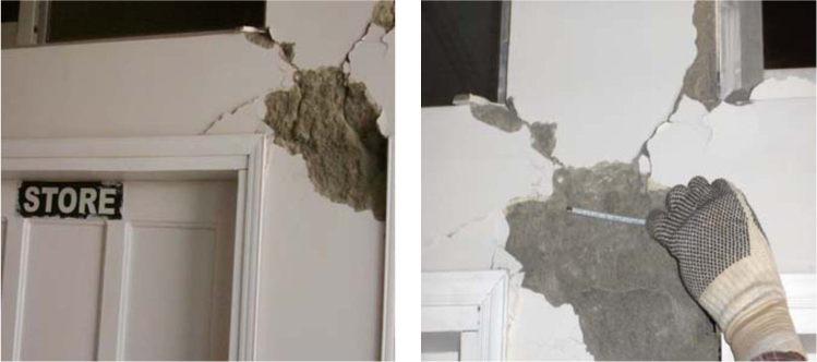
Combined In-Plane and Out-Of-Plane Effects
Masonry walls with openings are more susceptible to bidirectional (in-plane and out-of-plane) effects of ground shaking. In-plane shear cracks occur first which reduces the strength of walls in the out-of-plane direction. This type of failure may be dangerous in the case of out-of-plane sliding of the wall. Figure 17 shows combined in-plane and out-of-plane failure of the masonry walls.

Combined in-plane and out-of-plane effects.
Out-Of-Plane Damages
Lateral Thrust from Inclined Roofs
Walls supporting an inclined roof experience lateral thrust in their out-of-plane directions. During strong ground shaking produced by an earthquake, this thrust may be large enough to cause the walls to collapse in the out-of-plane direction or get seriously damaged. In the absence of reinforced concrete beams at the roof level, the building fails to produce a box-type behavior resulting in greater vulnerability of masonry walls in the out-of-plane direction. Figure 18 illustrate some failures of the buildings caused by the lateral thrust of the inclined roof. This type of failure is responsible for the collapse of a large number of masonry buildings in Gari Habibullah, Balakot, and Kashmir.
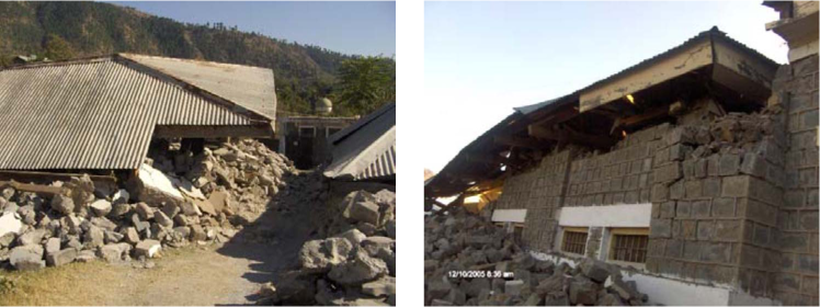
Collapse/damage of masonry walls due to lateral thrust from inclined roofs.
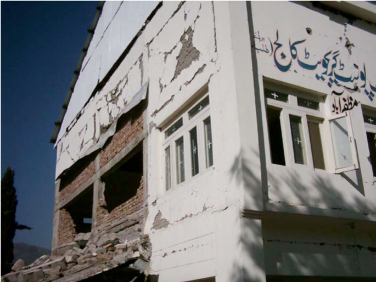
Failure of Building Corners
The corners of walls supporting roofs inclined in both directions are damaged due to the lateral thrust applied by the roof in addition to the inertial forces. The in-plane rotation of the rigid diaphragm also induces this type of failures at the corners. The lack of proper connection between walls and between walls and floor make the corners more vulnerable to cracking. Figure 19 illustrate this type of failure.
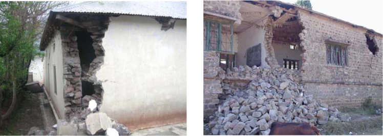
Damaged corners of buildings in Muzaffarabad.
Separation of Orthogonal Walls
Due to the lack of connection between orthogonal walls, separation of walls occurs due to out-of-plane vibration. The resistance offered by the in-plane walls to the bending of out-of-plane walls depends on the tensile strength of masonry. Separation of orthogonal walls occurs whenever this tensile strength is exceeded. Shear stresses due to flange-action make the wall intersections more susceptible to cracking. Figure 20 shows separation of walls at intersection with other walls and floor.

Separation of walls due to lack of connection between orthogonal walls (left figure shows the damages due to main shock and was taken during building inventory survey in Muzaffarabad).
Damages at Walls Adjacent to Roof
In many buildings, ventilators are constructed adjacent to floor slab with small length of wall in between them. Because of the out-of-plane vibration, these short piers get severely damaged. In some instances the piers get completely collapsed and the floor settled down. Figure 21 shows damages to short piers adjacent to roofs in Muzaffarad, Gari Habibullah and Mansehra.
Damage at walls adjacent to roof (left figure shows the damages due to main shock and was taken during building inventory survey in Muzaffarabad).
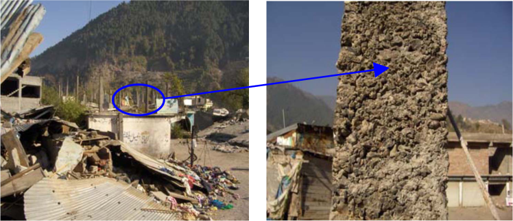
Collapse of External Veneer of Masonry Walls
The rubble stone masonry constructed in weak mortar and without providing through stone are liable to fail at very low level of seismic excitation. The external veneer usually fails first in the out of plane direction. This type of failure (Figure 22) was more prominent in Gari Habibullah, the old city of Muzaffarabad, and the rural parts of the affected area.
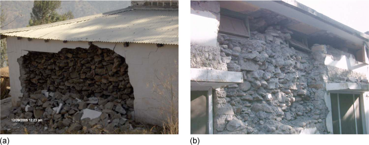
Collapse of external veneer of stone masonry wall.
Out-Of-Plane Failure of Gables
The collapse of gable walls was observed in many buildings of Muzaffarabad. Absence of vertical loads and adequate connection between gable wall and roof, the gable walls are more vulnerable to failure in the out-of-plane direction. Figure 23 shows collapsed gabled walls of two buildings in Muzaffarabad.
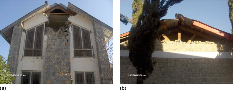
Out-of-plane failure of gables.
Nonstructural Masonry Elements
Out-Of-Plane Failure of Infill Walls
Brick or block masonry have been commonly used in the construction of infill walls in concrete framed buildings. After the construction of columns and beams, masonry in-fill panels are constructed with no separation between walls and columns while the gap between walls and beams are filled with mortar. Due to the lack of proper connection between walls and beams/columns, the infill walls are more susceptible to out of plane failure even for low level of ground shaking. Figure 24 shows out of plane failure of infill walls.
Out-of-plane failure of infill walls.
In-Plane Failure of Infill Walls
The concrete-framed buildings have typically been analyzed and designed as skeletal structures without any masonry infill walls. On the other hand, buildings are constructed in such a manner that no separation is left between walls and beams/columns, resulting in a composite structure in which both concrete frame and infill masonry walls resist together the seismic demand of the earthquake ground motion. Consequently, the infill walls fail in in-plane action and redistribution of loads occur, putting demand on the column (Bruneau 2002). The infill walls of many concrete framed buildings were found damaged in diagonal shear throughout the affected area. Crushing of masonry unit (concrete blocks) was also observed.
Failures of Appendages Supported on Unreinforced Masonry
It has been a routine practice to build large water tanks at the top of the building, and they are supported on vertical masonry elements. In concrete-framed structures, the water tanks are mostly simply supported on concrete columns. During ground shaking, supporting elements could not resist the increased structural demand resulting from inertial forces of the large mass of water. Consequently, dislocated water tanks severely damaged the buildings. Figure 25 illustrates the falling water tanks.
Failure of appendages supported on unreinforced masonry elements (figures show the damages due to main shock and were taken during building inventory survey in Muzaffarabad).
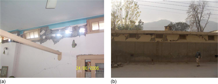
Failure of Boundary and Parapet Walls
Normally, the boundary and parapet walls are constructed of single-leaf masonry wall. Boundary walls are 1.5 to 2.0 m (5 to 7 ft) in height, whereas parapet walls are 0.75 to 1.5 (2.5 to 5 ft) high in the residential buildings of the affected area. The boundary and parapet walls throughout the affected area were either collapsed or severely damaged because of the strong ground motion. Figure 26 shows damaged boundary walls.
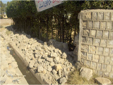
Failure of standing walls in Abbottabad.
No evidence of liquefaction or failure of buildings due to foundation failure was found. However, the details of slope failure could be found elsewhere.
Conclusions
Despite the fact that Pakistan is situated in a seismically active region, no serious efforts had been undertaken for the assessment of seismic hazard and development of a seismic building code prior to the Kashmir earthquake. Buildings designed according to 1937 Quetta building code performed well during the 1941 earthquake. The 1986 Pakistan building code did not address the analysis and design of either concrete or masonry structures for lateral loads. Seismic zoning maps given in the code underestimated the seismic hazard of the area affected by the Kashmir earthquake. The 2007 Pakistan Building Code, developed after the Kashmir earthquake, is mostly based on the 1997 Uniform Building Code. Indigenous research is required to evaluate analysis and design parameters specific to materials and structural systems used in Pakistan.
It was observed during the reconnaissance surveys that most of the buildings were nonengineered or semi-engineered. The stone masonry buildings that comprised 30–35% of the building stock were severely damaged because the use of rubble stones, mud mortar, or weak cement-sand mortar (1:8 or 1:10) and lack of connection between walls and walls and floor.
Concrete block masonry buildings were the second most damaged buildings. The damages could be attributed to use of very low strength blocks, lack of confinement of unreinforced block masonry wall panels and poor workmanship. Brick masonry buildings performed relatively well due to better workmanship and material properties. However, the damage in brick masonry buildings could be attributed to the lack of confinement of wall panels and poor configuration.
Reinforced concrete buildings were mostly designed for gravity loads. However, it was observed that reinforcement detailing did not even comply with code requirements for gravity load design. Improper confinement of the column joints, insufficient lap splice length and lap location, soft story effect, and the use of extremely weak concrete may be attributed to the damages observed in the concrete buildings.
It is important to carry out risk and loss assessment of the major cities. Low-cost retrofitting guidelines should be developed. Lastly, a strategy for the enforcement of a seismic code throughout Pakistan should be devised.