
Abstract
The Mw 7.0 earthquake that struck Haiti on 12 January 2010 exposed deeply rooted weaknesses of the built environment. Numerous factors contributed to the severity of this disaster, including building materials, design, construction, and oversight, all of which were deficient and represent a lower bound condition. Yet despite poor quality, some structures were undamaged. A minor change in construction sequence resulted in an altered load path and a drastically different outcome for some buildings. Infilled frame systems performed poorly and account for the majority of structural collapses. Buildings assembled in a manner similar to confined masonry, however, performed well and experienced little damage. Damage assessments conducted around Port-au-Prince reveal that 20% of the housing stock was completely destroyed and 27% was significantly damaged. These assessments illuminate Haiti's vulnerability to future and repeated devastation, since the remaining damaged and brittle structures could likely not sustain additional excitation.
Introduction
On 12 January 2010, a Mw 7.0 earthquake struck the southern region of Haiti, 16 km from the populous capital, Port-au-Prince. The number of reported fatalities varies widely: the government of Haiti estimated 316,000 were killed while an unpublished 2011 report commissioned by the U.S. Agency for International Development estimated the death toll was much lower, between 46,000 and 85,000 (Associated Press 2011). A year after the earthquake 810,000 remained displaced (USAID 2011). Damage assessment studies reveal that 20% of structures in the Port-au-Prince region were severely damaged or destroyed and another 27% require major repairs (UNOPS 2011). Total damages and losses are estimated to be 7.8 billion USD, equivalent to 120% of Haiti's 2009 GDP (UNEP 2011). In 35 seconds of shaking, this modest seismic event became one of the deadliest and costliest natural disasters in modern history.
Approximately 90% of the building stock in the Port-au-Prince metropolitan region is residential housing (ImageCat 2010). Nearly two thirds of these buildings, across all economic classes, are one-story single family dwellings constructed in a homogeneous manner with reinforced concrete frame elements infilled with unreinforced masonry (IHSI 2003). Housing was the single most affected sector as a result of the earthquake: repair and replacement costs compose 40% of the total estimated losses (2.3 billion USD).
The authors traveled to Port-au-Prince and surrounding areas in the weeks following the event as members of the Earthquake Engineering Research Institute's reconnaissance teams. A primary reconnaissance objective was to document the performance of Haiti's nonengineered low-rise structures, the vast majority of which are residential. Building use, methods of assembly, material quality, and structural performance were closely observed. While a detailed technical study was not conducted, our informal observations matched closely with robust statistical studies conducted pre- and post-earthquake.
According to damage survey results, over half of residential homes remained unscathed, yet the quality of building materials and construction techniques for these buildings did not vary significantly from those that had collapsed. The authors’ observations confirm these data. Undamaged houses were constructed immediately adjacent to others of nearly identical construction that were completely destroyed. This manuscript attempts to explain how these drastically different outcomes resulted.
Historically, traditionally assembled confined masonry has performed well in global earthquakes with little documentation of collapse. Thus, capturing failure mechanisms of these systems was a prime motivation for reconnaissance. Field observations revealed that buildings assembled similar to confined masonry, with the masonry wall erected prior to the frame, did not have load bearing walls. This is an important characteristic of confined masonry which affects the load transfer mechanism. Nonetheless, these systems still performed well. The staggering of masonry units within the column cavity and concrete adhesion resulted in increased bond and continuity between the wall panels and adjacent columns. Construction materials and craftsmanship were of such poor quality, however, that small deviations from this assembly technique resulted in structural failure similar to infilled frame structures. Traditional infilled frame systems lack a bond between the masonry walls and frame elements. These systems performed poorly in the earthquake and account for the majority of structural collapses and fatalities.
Pre-Earthquake Housing Situation
The predominant structure type seen in Haiti is a low-rise, nonengineered building constructed of unreinforced masonry walls framed by slender concrete columns. Hollow concrete block is the primary masonry unit used; other types, including fired clay brick were not observed. Heavy concrete slabs are used for floors and roofs. Other roofing methods include sparse wood frames overlaid with lightweight corrugated metal and concrete blocks cast within the slab. The latter exploits the voids of concrete block, reducing the volume of concrete used.
Most buildings are one to three stories and are used for single family dwellings or small businesses. Apartment buildings did not appear prevalent; most families reside alone in one house regardless of income. Most homes are designed and constructed by the owner or a local mason. Because residences are commonly constructed over time as funds are acquired, construction is inconsistent and haphazard. Load paths are frequently discontinuous and member sizes insufficient, particularly columns when additional floors are later added. For these reasons, Haiti's archetypical construction is referred to as “nonengineered.”
In 2001 and 2009, the Government of Haiti commissioned housing and infrastructure surveys of a combined 9,200 citizens in rural, urban, and metropolitan regions of the country. The results of these surveys confirm our observations of the housing stock in Port-au-Prince and surrounding municipalities (IHSI 2003, Lunde 2009):
One-story, single family dwellings comprise 63% of the housing stock in metropolitan Port-au-Prince and 72% in surrounding urban areas. Roughly 60% of all residential structures in Haiti are regular one-story dwellings, regardless of economic class. Other housing types include: multistory house or apartments (10%); “taudis/ajoupa” or slums (14%); “kay até” or mud houses with joined roof and walls (6%); and other (7%). Regular one-story houses are predominantly constructed with concrete, block, or stone (76%), as categorized by the survey. Nearly all multistory dwellings are built with these materials (97%). Regular one-story houses are usually built with concrete floors (64%); the remainder use compacted earth (31%). Multistory dwellings are also normally built with concrete floors (69%) with most of the remainder reported as tile or wood board.
As Port-au-Prince became the dominant economic center of Haiti over preceding decades, uncontrolled housing developments grew around the city. Known by the French term bidonville, these unauthorized settlements are dense and lack formal planning, notably for natural hazards. A 1997 study revealed that two-thirds of the urban population around Port-au-Prince resided on just 22% of the inhabited land (PDNA 2010). Most of these settlements evolved on the steep hillsides above the city center, usually by means of squatting (Figure 1). Two-thirds of Haitians claim ownership of the land and house they reside in (IHSI 2003). Home ownership acquisition is reported predominantly as “construction” (84%), rather than purchase (6%) or inheritance (8%).
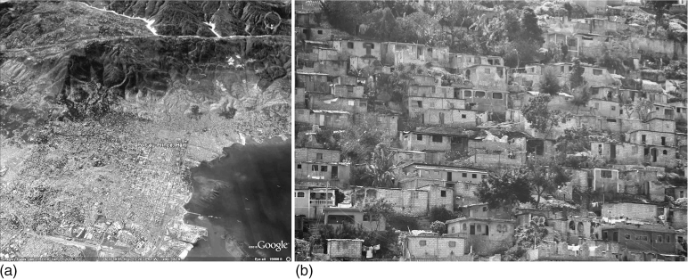
(a) Bidonville housing developments surround Port-au-Prince in the steep foothills (Google Earth). (b) Typical low-rise, nonengineered housing development on hillsides (Photo courtesy A. Lewis).
Building Materials
As outlined above, the building materials and assembly methods of Haiti's housing stock are homogeneous, suggesting that construction quality is also of a similar level throughout the country. The January 2010 earthquake, therefore, unbiasedly affected the entire population. Understanding Haiti's conformative building practices illuminates this condition and subsequent reasons for the widespread damage.
Concrete Materials
Cement
Based on the authors’ observations of active construction sites and interviews with builders and suppliers, Type I Portland cement is used exclusively for all concrete elements, including hollow concrete blocks, columns, beams, roof and floor slabs, and mortar for foundations and wall panels. All cement is imported into Haiti; in-country production ceased following the privatization of the public cement company, Cimint d'Haiti in 1997.
Sand
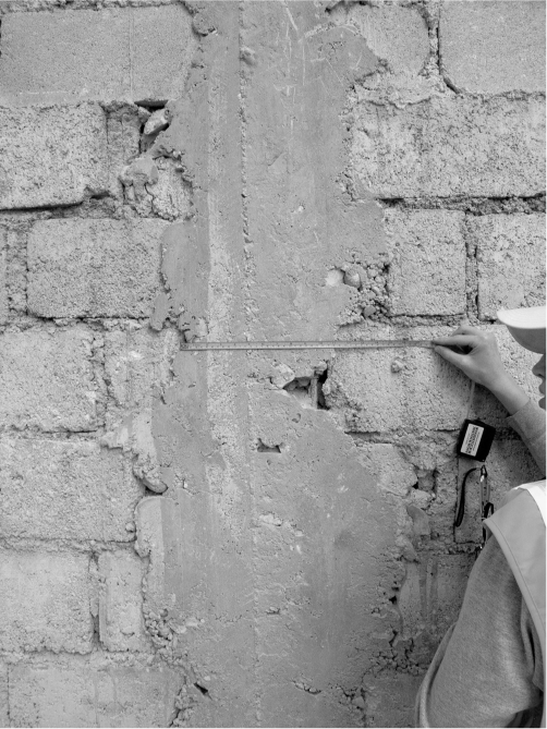
Unwashed beach sand was regularly used in concrete mixes in the past. The high salt content facilitates corrosion of steel reinforcement and can lead to complete loss of tensile strength. A past campaign by the government to discourage the use of beach sand appears to have been successful. Residents are aware it is an objectionable building material and its use appears to have ceased and been replaced with river sand. Unfortunately, most buildings subjected to the January 2010 earthquake had been constructed with beach sand. Among other reasons, corroded reinforcement contributed to structural failures because of a loss of tensile capacity of the reinforcement (Figure 2).
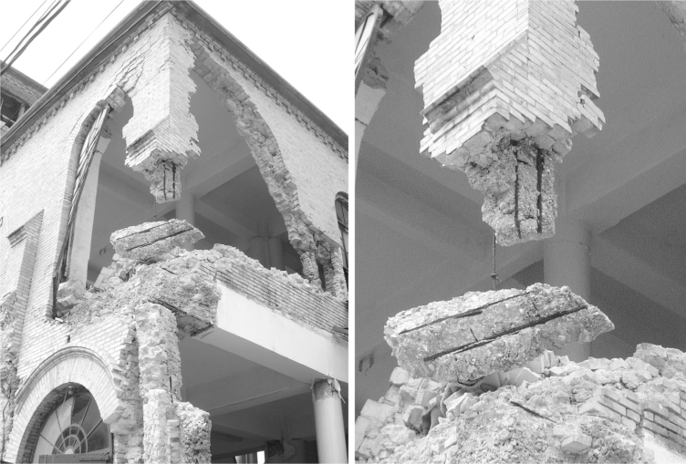
Corrosion of steel reinforcement from the use of beach sand contributed to the failure of the Sacred Heart church in Port-au-Prince.
While river sand is a good alternative to beach sand, aggressive mining of it comes with environmental consequences. Its removal reduces the amount of sediments transported to river mouths and beach estuaries, diminishing natural coastal barriers (Cambers 1998).
Aggregate
Haiti has large natural deposits of limestone throughout the country. Because of its abundance, limestone is commonly used for both small and large aggregate. It is quarried from the hills above Port-au-Prince, the largest of which, “La Boule,” produces a light colored weak chalky limestone. According to past USGS investigations, limestone from this area contains rudists, tubular mollusks from the Cretaceous (Woodring 1964). The shells of these organisms are composed of calcite and aragonite, forms of calcium carbonate that compose limestone. A USGS cement specialist hypothesized that if these shells are fragile, then they are the likely cause of the weak chalky characteristics (Van Oss 2010). Alternatively, the sedimentary environment in which the limestone formed may have prevented natural cementing of the material.
Haitian builders take advantage of limestone's natural cementing properties by using less cement in concrete mixes in place of more limestone aggregate. This practice is particularly common in concrete block manufacturing. The combined decreased quantity of cement and increased quantity of limestone, which has a lower compressive strength than rock, reduces the overall compressive strength of typical concrete in Haiti. A month after the earthquake, Haiti's public works ministry prohibited the use of La Boule material for construction. They instead recommended using sand and rocks from river beds. Despite this decree, piles of limestone aggregate were frequently seen at construction sites during reconnaissance (see Figure 3).
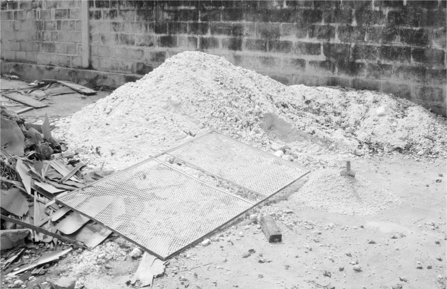
La Boule limestone aggregate gradated at a construction site.
Although river rock has a higher compressive strength than limestone, its smooth surface diminishes bond strength with the cement matrix. Exacerbating this is the use of very large river rock; 3 inch to 6 inch rocks and larger were commonly seen during reconnaissance. Crushed granite, typically ¾ inch in the United States, was only observed at the national material testing laboratory. The removal of river rock was observed in select locations where it had been intentionally placed for scour protection of bridge foundations.
Proportions and Placement
Along with poor quality aggregates and insufficient cement, concrete mix proportions were frequently observed to have high water content in order to ease workability and generate more concrete volume, thus lowering costs. As was commonly observed, the concrete bond strength was incapable of fracturing through large rock aggregate (see Figure 4). For larger construction projects that require delivery of concrete by mixing truck, the mixes also tend to have high water content because of evaporation and transportation delays. Conversely, water content can also be too low if water is difficult to obtain or transport. In general, mix proportions and technique were not observed to depend on the intended use of the concrete, including for mortar, structural frame elements, or concrete blocks.
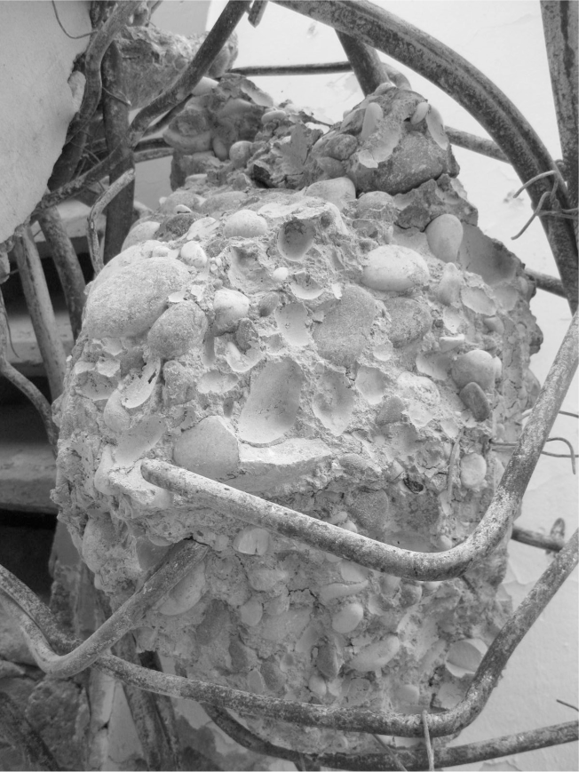
Weak concrete bond is evident by the lack of fracture through large aggregate.
As was frequently observed, concrete is commonly mixed on the ground at construction sites resulting in heterogeneous batches and inconsistencies between batches. The concrete is shoveled directly into formwork or block molds with no vibration or consolidation effort to remove air voids (see Figure 5). Large voids were commonly seen as big as a softball in finished construction. In larger or higher-end projects, a small mixer or concrete truck was observed with a bucket brigade transferring the concrete for placement. Again, no observed effort was made to consolidate.
Examples of poor quality concrete, including excessively large rock aggregate, discontinuous pour, lack of consolidation, and poor reinforcement detailing (photo (a) courtesy A. Irfanoglu).
Concrete blocks are commonly produced at or near construction sites. The blocks are formed, extracted, and dried rather than cured. The drying process generally occurs in a large open area with no cover, resulting in limited hydration of the concrete. Typical block dimensions are 15.75 inches × 7.0 inches × 6.0 inches (see Figure 6). Shell thickness is approximately 1 inch. Grouting of concrete blocks was never observed.
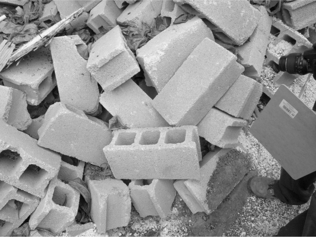
Typical concrete masonry blocks.
Strength Properties
In an effort to quantify the strength of commonly used concrete and concrete block construction materials, EERI reconnaissance members secured numerous samples for strength testing. Eight concrete blocks were taken in-situ and tested in compression. Average peak strength was 1,638 psi with a standard deviation of 365 psi. Typical concrete block strength in the United States is 1,900 psi. Two fresh concrete samples were collected in cylinders from active construction sites and tested in compression. Both samples were sealed for transport to the United States where they were wet-cured before testing. Peak 28 day compressive strength of the first specimen was 1,260 psi. Peak 28 day strength of the second sample was just 410 psi. A third forensic concrete sample was collected from the Hotel Montana compound. It was cut into a rectangular prism and tested in compression; peak strength was 1,754 psi. For seismically resistant design in the United States, minimum specified concrete strength is 3,000 psi.
Steel Reinforcement
Steel reinforcement in Haiti is imported in large, tightly bound coils approximately 3 feet in diameter. The coils are straightened and sold in lengths of 30 feet; these pieces are then bent in half for transportation (see Figure 7). Once on site, the reinforcement is cut and re-bent into workable geometries. All told, steel reinforcement may undergo three large deformations before placement (Anonymous 2010). Most of the reinforcement is sold as “ungraded,” although Grade 60 rebar can be specially ordered. According to interviews with builders, when the price of steel increased globally in 2008, diameters of ½ inch and
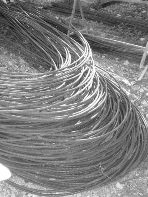
Commonly used ungraded reinforcement bent for transport (Anonymous 2010).
Historically, many of Haiti's low-rise structures were assembled with smooth reinforcement. The availability of smooth bar for purchase ended in 2000. Although deformed rebar is the only option for new purchase today, reinforcement of any kind, including smooth, was seen meticulously extracted from destroyed buildings to be used for rebuilding following the January 2010 earthquake (Figures 8 and 9).
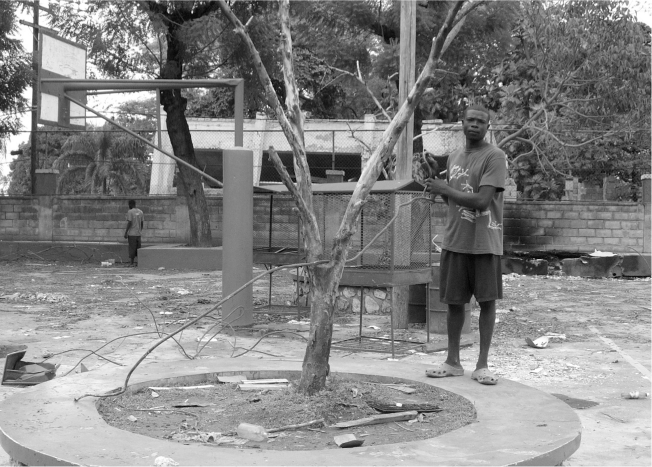
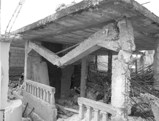
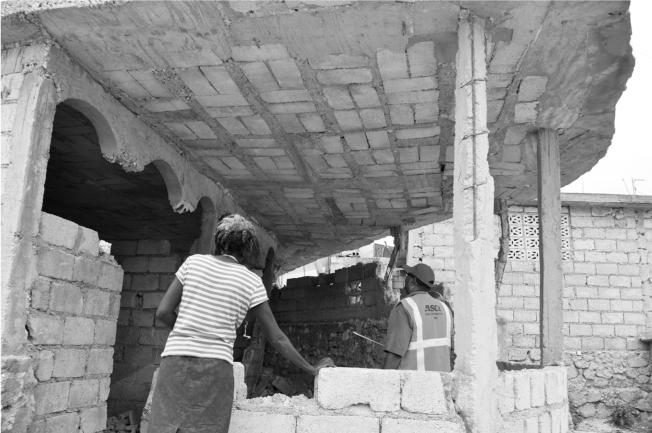
Straightening rebar that had been removed from a collapsed building to be reused in reconstruction.
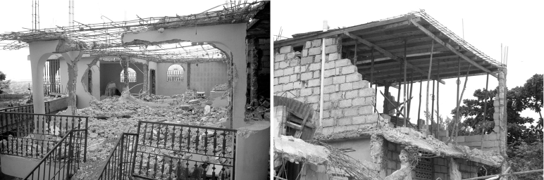
Rebuilding in the same configuration. (a) Concrete is meticulously removed from around steel reinforcement of the roof slab. (b) A damaged residence is prepared for pouring.
Strength Properties
To quantify the strength of steel reinforcement used in common construction, numerous samples were secured for strength testing. The first set of specimens included six smooth and deformed bars of various sizes that were representative of reinforcing used in nonengineered construction. Bar sizes ranged between #2 and #5. Yield stresses were between 43 ksi and 57 ksi; ultimate strengths were between 66 ksi and 82 ksi. These results are typical of Grade 40 or 60 reinforcing steel.
A second set of rebar specimens was secured and tested by MCEER and highlight the adverse effect of repeated bending. Three nominal ½ inch bars were tested in tension; two had been bent and one had not. Ultimate tensile strength did not vary significantly between the bent (98 ksi and 111 ksi) and unbent (108 ksi). However, the effect of pre-bending the rebar on performance is highlighted by the tensile strain results. Ultimate tensile strain of the unbent bar was 22%, two to five times greater than the bent specimens (4% and 11%).
These testing results suggest that the problem of structural performance is not attributable to the strength of available steel reinforcement. Instead, strain capacity, insufficient area ratios, use of nondeformed bars, and poor detailing were the primary contributors to structural failures. More details on the material testing can be found in Marshall (2011).
Observed Construction Methods
Typical building construction consists of lightly reinforced concrete columns spaced at 7 to 12 feet along perimeter and interior walls. Typical story height is 8 to 10 feet. Reinforced concrete beams or a thick slab spans between columns; the latter is more prevalent. Detailing at the beam-column or slab-column joint is limited to longitudinal bars passing through the joint; additional transverse ties are not commonly added. Beams are frequently excluded altogether as gravity carrying components. Their use appears dependent on slab thickness, column spacing, and architectural intent. When they were seen during reconnaissance, beams lacked concrete and reinforcement continuity across the beam-slab interface. This prohibits the development of a standard T-beam mechanism and thus vertical load transfer (see Figure 10).
Discontinuity between beams and slabs prohibits the beams from carrying vertical load.
Floor and roof slabs are constructed in one of two ways: solid or voided. A solid slab is lightly reinforced with a single layer of bidirectional steel spaced at roughly 9 to 12 inches. Voided slab construction utilizes masonry blocks to reduce the volume of concrete. In this case, the blocks are placed in a grid and form a bidirectional system of reinforced concrete beams nested within the blocks (see Figure 11). Block placement can be haphazard and lack regularity. Slab reinforcement was occasionally observed to span through the block voids. Typical slab thickness for this type of system exceeds the block width or height (7 inches) in order to provide a finished surface. In addition to concrete slabs, light gauge metal with timber or steel trusses is also a common roofing method.
Example of voided slab construction with blocks arranged in grids to facilitate bi-directional beams (Photo courtesy A. Irfanoglu).
Column dimensions are roughly 7 to 12 inches in the wall direction and the width of a masonry block (7 inches) in the perpendicular direction. Four #3 or #4 longitudinal bars were most commonly observed in columns (see Figure 12), providing a typical reinforcement ratio between 0.005 and 0.016. Smooth and deformed bars are often used interchangably in the same structure and within the same column. Typical transverse reinforcement in the columns is #2 smooth ties spaced at 6 to 12 inches. There were no observed instances of tighter tie spacing in expected hinge regions. An overlap of 2 inches was typically seen at tie ends. In some cases, this overlap occurs at the column corner around a longitudinal bar, providing an insufficient 90 degree hook. However, in many cases the overlap was also observed between longitudinal bars, resulting in no bent hook and even less confining capacity. No observations were made of 135 degree ties typical of seismic resistant construction.
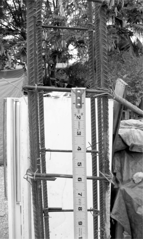
Typical longitudinal and transverse steel reinforcing for a column (Photo courtesy of P. Coats).
Unreinforced masonry walls have a single wythe staggered block arrangement. No mechanical connection to other structural elements, such as concrete slabs or columns, was seen. Horizontal bed joints are commonly ¾ inch thick. Vertical joints vary between 0 and ¾ inch. In some cases a thin coat of mortar material is applied to the wall face to produce a smooth finish. Observed openings in walls included large windows (commonly 3 feet square); patterns of missing blocks (i.e., every other block excluded in a row); or decorative blocks to allow light penetration. These openings are commonly positioned immediately below the slab above, thus utilizing the slab as a lintel. Reinforced concrete bond beams were also commonly seen, positioned over window openings and running the length of a wall or encompassing a building, as seen in Figure 13.
Example of a bond beam that spans over the second-floor window openings and wraps around a portion of the building.
When future expansion of a building is planned, longitudinal reinforcement from columns below is extended through the slab. While this provides modest continuity between existing and future columns, detailing in the lap region does not meet ACI-318 provisions, including 2 inch transverse tie spacing (based on bar diameter) and lapping within a potential hinge region (ACI-318 2002).
Overview of Infilled Frame and Confined Masonry Systems
Traditional infilled frame construction consists of reinforced concrete frames with masonry infill walls. The frame elements—columns, beams, and slabs—are poured and finished before masonry is placed. This construction type is identifiable by a clean delineation between masonry walls and columns. Under well engineered circumstances the frame is moment resisting, designed to carry all vertical and lateral forces. The masonry wall panels are normally considered non-structural elements and are not included in capacity analysis, despite well documented evidence of their influence on structural response. Infilled frame construction results in a lateral force resisting mechanism composed of two independent systems: a shearwall and a moment resisting frame. Dissimilar stiffnesses of the two systems commonly results in localized damage to the columns and wall during in-plane action (see Figure 14). Out-of-plane, toppling of the wall panel is common.
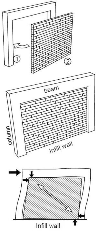
Infilled frame construction sequence and lateral force resisting mechanism (Brzev 2010).
Confined masonry structures resemble infilled frames but with a reversed construction sequence, resulting in a significantly different structural response. The masonry walls are first assembled then used as formwork for the surrounding frame elements, including columns, beams, and slabs. This seemingly minor construction difference from infilled frame systems results in vertical load bearing on the wall and larger friction force development among the masonry units. Unlike infilled frame construction, confined masonry resists in-plane lateral loads with the combined mechanism of a moment frame and shearwall. In-plane loads are transferred to the masonry wall by frictional contact at the column-wall and beam-wall interfaces (see Figure 15). Regarding the former, the staggering of masonry units in a saw-tooth manner within the column cavity produces a mechanical connection similar to multiple shear keys. Because the masonry wall is used as formwork, the column boundary is prescribed by the saw-toothed pattern. A research effort is underway by the primary author to quantify the effect of this interface on lateral load transfer.
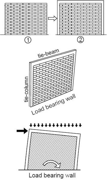
Confined masonry construction sequence and in-plane lateral force resisting mechanism (Brzev 2010).
Confined masonry also performs well in out-of-plane loading particularly in comparison with infilled frame construction. Vertical load bearing on the walls improves force transfer across the beam-wall and column-wall interfaces. The increased compressive stress reduces tensile stress and strain across the wall panel and facilitates two-way bending (see Figure 16). Arching action is achieved because of the mechanical saw-toothed connection at the column-wall interface.

Two-way bending mechanism of load bearing confined masonry walls subjected to out-of-plane forces (Brzev 2010).
Infilled Frame and Confined Masonry Systems in Haiti
As highlighted in previous sections, Haitian construction practices are haphazard and of poor quality. Builders often use different column and reinforcement sizes and construction techniques on the same building, unaware of any subsequent effects on performance. Specifically, erecting the masonry wall first or building the frame first does not result in a significant change in appearance. The two techniques use the same materials and in similar quantities; to an untrained individual, there's little discernible difference.
In order to distinguish between construction sequences and subsequent performance, the terms “column-first” and “wall-first” are used herein to describe those construction practices in Haiti which are similar to infilled frame and confined masonry systems, respectively. While the terms “infilled frame” and “column-first” can be used interchangeably, the terms “confined masonry” and “wall-first” cannot. Significant differences exist between traditional confined masonry and the wall-first systems that exist in Haiti. Properly constructed confined masonry results in vertical load bearing on the masonry wall panels. Common building practice in Haiti, however, results in a gap between the top of the wall and the beam or slab above, prohibiting vertical load transfer (see Figure 17). Subsequently, two-way bending cannot develop across the wall. The benefit of erecting the walls before the columns is therefore restricted to arching action alone. For this reason, true confined masonry construction was not observed in Haiti and is instead referred to as “wall-first” construction.
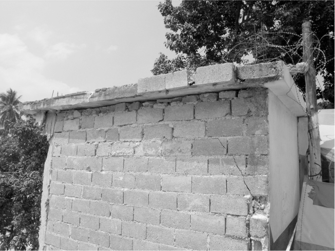
Masonry walls are built short of the roof slab for all types of masonry construction; block debris is added to fill in the gap.
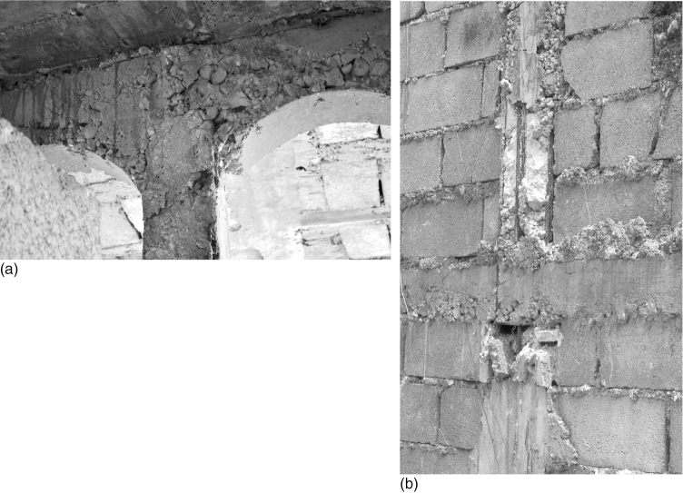
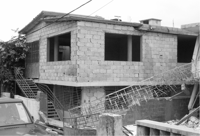
Wall-first and column-first construction appeared to be equally prevalent in Haiti. During reconnaissance, column-first construction was easily identifiable because of delineation or even a gap between the wall panel and the adjacent column. Wall-first construction was identifiable by the absence of this division and the presence of concrete oozed around individual masonry units. Evidence such as that shown in Figure 18 strongly indicates that the wall was in-place prior to pouring of the column.
Wall-first construction is identifiable by the oozing of the column concrete around the masonry blocks.
Performance of Nonengineered Structures during the January 2010 Earthquake
Infilled Frame/Column-First Buildings
For those structures assembled with a column-first technique, observed performance during the January 2010 earthquake was poor and consistent with the expected behavior of infilled frame systems. Initially, masonry walls contributed to and increased the lateral stiffness of the surrounding frame system. Once the masonry cracked and deformation demands increased, interaction between the wall panel and columns resulted in localized damage to both. Lacking out-of-plane resistance, masonry infill frequently toppled out-of-plane (see Figure 19), leaving the adjacent slender columns unsupported. Ultimately, insufficient beam-column joint detailing led to joint damage and the formation of sway mechanisms. This damage progression and failure mode were likely the most common means of collapse of low-rise, nonengineered buildings in Haiti and were responsible for the majority of fatalities. Inadequate transverse reinforcement of the columns also resulted in frequently observed shear failures, compression failures, and column bar buckling.
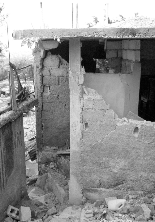
Infilled frame construction is distinguishable by clean lines between columns and walls. Typical failure is out-of-plane toppling, as shown.
Wall-First Buildings
As previously discussed, construction of a masonry wall prior to the frame results in a modest bond or saw-toothed connection between the columns and masonry wall. For this reason, wall-first buildings constructed with a significant column-wall bond experienced little to no damage from the earthquake (see Figure 20). The extent of damage observed in this case was limited to minor cracking around window and door openings. However, Haitian construction is of such poor quality, and in fact represents a lower bound condition, that this seemingly minor change of assembly technique defined the difference between adequate force resistance and collapse during the 2010 earthquake.
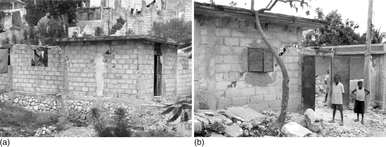
Wall-first construction in Haiti, similar to traditional confined masonry. (a) Typical building on a rock rubble foundation. (b) Damage around openings from the January 2010 earthquake. This was the most severe damage observed to these building types. (Photos courtesy S. Brink)
Based the authors’ observations, the distance that the staggered masonry units extended into the column cavity appeared to directly affect the amount of damage. As the column-wall interface became more flush and more closely resembled infilled frame construction, performance diminished even despite the wall-first construction sequence (see Figure 21). Frequently, a completely flush interface with no brick staggering was observed between the masonry wall and column. In this case, only contact adhesion existed between the concrete and the masonry wall; no shear key action could develop. Nonetheless, the authors speculate that even this lower bound interface may have helped mitigate or delay collapse, as numerous undamaged or slightly damaged buildings were observed with this negligible bond.
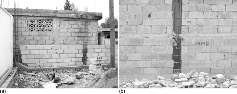
Wall-first construction. (a) Proper staggering of blocks within the column cavity. (b) The lack of block staggering results in behavior similar to infilled frame (Photo courtesy D. Ballantyne).
Several examples of out-of-plane U-shaped wall failures were observed for buildings assembled with a wall-first technique, for which masonry units remained attached to the columns. The presence of these units indicates that the column-wall bond was not the weak link, but that the displacement capacity of the wall was reached.
Despite the successful performance of wall-first construction in Haiti, poor quality design and craftsmanship are pervasive. The use of a wall-first or column-first construction technique is inconsistent; a wall may be bookended by a column at one end and unsupported at the other. This gross lack of redundancy and consistency in the design and assembly of Haitian houses frequently facilitated the rapid escalation from a single component failure to global structural collapse. Residents should not assume that because their house withstood the earthquake that it was built properly and is safe from future seismic events.
Damage Overview: Perception and Statistics
Hundreds of buildings were observed during earthquake reconnaissance, from which the authors made a broad observation that the performance of Haiti's houses during the earthquake appeared to be bimodal: they seemed to either survive intact with little to no damage, or they were completely destroyed. Buildings with a moderate level of damage indicating energy dissipation or ductility capacity, such as shear wall “X” cracks, moment failures, and permanent displacements, were not frequently observed. This lack of moderate damage, in light of the short duration of the earthquake, is a testament to the brittle nature of Haiti's housing stock.
As discussed, variations in construction technique contributed significantly to the severity of damage of a structure. Other factors, including topographic and soil amplification effects, also resulted in concentrated areas of severe damage. Yet even in these areas some structures remained intact and undamaged. Anecdotally, two hillside residential communities are considered with similarly constructed homes. One of these communities suffered extreme damage: of roughly 62 homes considered, 45 were completely destroyed and the remaining 17 appeared undamaged (73% collapse rate). The second community is located just 1 km away. Of roughly 70 homes surveyed, there were no collapses and just three instances of isolated out-of-plane wall failures. The difference between these two communities not only highlights the significant impact of ground conditions, but also the generalized observation of bimodal structural performance.
Several damage assessment surveys were conducted in the aftermath of the January 2010 event to quantify the number of destroyed buildings and the damage grade distribution. Data collection began within days after the earthquake to serve rapid assessment and response needs and continued for over a year to estimate total losses and establish a framework for recovery. The results of three of these surveys are presented to highlight the widespread and unbiased destruction and to illuminate the authors’ perceived bimodal performance.
Post-Earthquake Damage Assessment Surveys
Imagecat/Geo-Can
Immediately following the January 2010 earthquake, the World Bank partnered with ImageCat and the Global Earth Observation Catastrophe Assessment Network (ImageCat/GEO-CAN) to generate building damage estimates. Aerial and satellite imagery was taken of locations throughout Port-au-Prince and select cities that coincide with areas visited by EERI reconnaissance members. High resolution (50 cm) satellite imagery and very high resolution (VHR; 15 cm) aerial imagery was used to examine structures from a vertical-only perspective. Analysts were asked to identify only buildings which they could confidently classify as very heavily damaged or collapsed, in accordance with the European Macroseismic Scale 1998 (EMS-98) Grades 4 or 5, respectively (see Figure 22). A total of 29,056 destroyed buildings were identified by means of observed debris fields and skewed roof lines. When damage was ambiguous or difficult to determine the buildings were excluded from the database. For this reason, there is very high reported confidence of accurate damage assessment for individual buildings (76% confident for Grade 4 and 90% for Grade 5; ImageCat 2010).
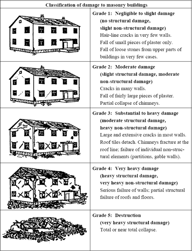
Damage classification grades of masonry buildings based on EMS-98 (Grünthal 1998).
To put the counted number of Grades 4 and 5 buildings in context, ImageCat/GEO-CAN researchers used field surveys to approximate the total number of buildings that had been considered in the course of their analysis, including damaged and undamaged. Four field surveys were conducted around Port-au-Prince that represented different land use or occupancy types: residential high density, residential low density, shanty/informal, and commercial/industrial/downtown. Damage level proportions from these surveys, in combination with the actual number of Grades 4 and 5 buildings assessed from imagery, were used to estimate the total number of Grades 1, 2, and 3 buildings. This was done for each land use category. The results are shown in Table 1, where the number of counted Grades 4 and 5 buildings identified from vertical imagery are shown in boldface for each land use occupancy type. The corresponding number and percentage of Grades 4 and 5 buildings identified from field assessments is shown in italics.
Damage level distributions from ImageCat ground surveys (
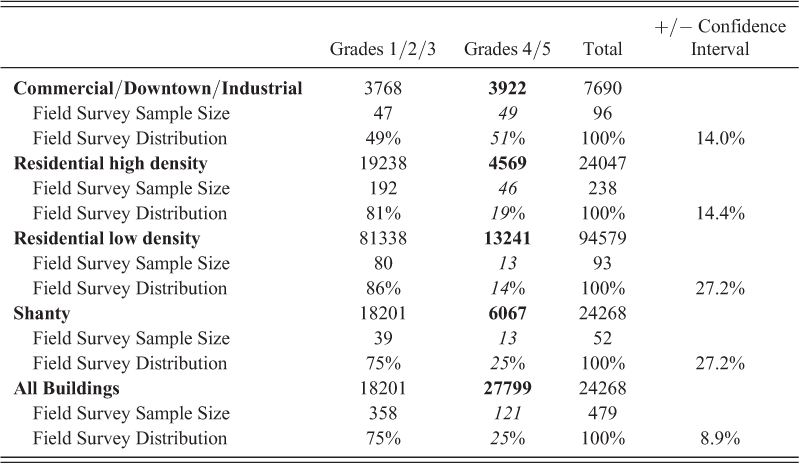
The process by which building counts were extrapolated for lesser damage grades employed small sample sizes relative to the populations represented, resulting in diminished confidence of accurate damage assessment. As shown in Table 1 under the All Buildings category, the overall sample size of 121 Grades 4 and 5 field surveyed buildings represents a population of 27,799 identified from vertical imagery. This representation results in a confidence interval of nearly 9% for a 95% confidence level. Thus, these data indicate that the percentage of severely damaged or collapsed buildings in Haiti could be as high as 34% instead of the 20% estimated by the Post Disaster Needs Assessment commissioned by the Government of Haiti (PDNA 2010)PDNA 2010.
Earthquake damage assessments are notoriously subjective. The ImageCat/GEO-CAN effort utilized over 600 volunteers, most with engineering expertise but with limited training in vertical imagery damage assessment. Variation in damage categorization is to be expected. ImageCat/GEO-CAN volunteers were instructed to grade only those buildings for which they had a high level of confidence of accurate assessment. Inevitably, by excluding structures that analysts were less confident about, many buildings were excluded from the count which should have been included. As an example, a two-story house observed by the authors sustained little wall damage, including no out-of-plane or in-plane failures. Yet the roof slab was rotated and precipitously supported on slender columns. Vertical imagery would have revealed no debris field and may not have been resolute enough to reveal the slab rotation. The structure was vulnerable to pancake collapse at the slightest perturbation. It is plausible that a building in this condition would not have been classified as Grades 4 or 5. Subsequently, the ImageCat/GEO-CAN damage assessment results could be a conservative representation of the actual damage distribution.
Pictometry
In order to gauge the accuracy of their results, the ImageCat/GEO-CAN team requested that a two part validation study be conducted using ground observations and Pictometry, aerial imagery taken at an oblique angle. This perspective allows for viewing of the sides of damage structures, resulting in a more accurate damage assessment than the vertical imagery collected by ImageCat/GEO-CAN. Pictometry can capture story collapses unlike vertical imagery, thus resulting in more Grades 4 and 5 assignments. Lesser damage, Grades 2 and 3, can also be identified in some cases. The most significant limitation of Pictometry is line-of-sight obstruction due to foliage.
The first part of the validation study compared damage assessments of 1241 buildings made by both ImageCat/GEO-CAN and Pictometry (Spence 2010). Results reveal that Grades 4 and 5 damage proportions were similar between the two methods. Damage assessment made by Pictometry resulted in 9.3% and 16.4% for Grades 4 and 5, respectively. ImageCat/GEO-CAN analysis resulted in 8.0% and 15.6% damage at Grades 4 and 5, respectively.
The second part of the validation study compared damage assessments made by both ImageCat/GEO-CAN and Pictometry against detailed ground observations (Spence 2010). A sample size of 124 buildings was used for this validation study. Results from this comparison study are striking and loosely support our observation of bimodal performance, as well as highlight the significant vulnerability of Haiti's building stock to future earthquakes. Ground observations reveal that 46% of structures suffered severe damage (Grades 4 and 5) during the January 2010 event. This is a significantly larger percentage of destroyed buildings than either ImageCat/GEO-CAN (17%) or Pictometry (29%) estimated. Further, the Pictometry method estimated that 50% of buildings were undamaged, yet ground observations suggest just 25% were undamaged. Subsequently, this validation study reveals that more buildings experienced Grades 2 and 3 damage than estimated by the ImageCat/GEO-CAN or Pictometry methods.
Although the authors’ perspective of bimodal performance is not clearly supported by these damage assessment results, the damage level proportions revealed by the field validation study may suggest an even more dire situation than expected. Ground surveys reveal that a significant percentage (29%) of structures experienced light to moderate damage, Grades 2 to 3, during the earthquake. While this percentage discredits the notion of a bi-modal performance, it instead alludes to the great vulnerability of Haiti's housing stock to future seismic events and subsequently to increasing damage levels. The brittle structures that sustained moderate damage during the January 2010 earthquake now have a greater likelihood of being destroyed in future events.
Unops Field Assessment
The Haiti Ministry of Public Works requested the assistance of the United Nations Office for Project Services (UNOPS) to conduct a large scale damage assessment. Over 400 Haitian engineers were trained to rapidly assess building damage into three categories in accordance with ATC-20: green, yellow, and red (ATC 1989). The green designation indicates the building is secure and does not present a structural risk. Yellow indicates the building should not be occupied but may be accessible if repairs are made. Red indicates that the building constitutes a risk and should not be occupied. These categorizations roughly correspond to the EMS-98 damage scale of Grade 1 (green), Grades 2 and 3 (yellow), and Grades 4 and 5 (red). The UNOPS ground assessment was conducted over the course of 12 months in Port-au-Prince and neighboring municipalities. As of January 2011, over 390,000 buildings had been assessed, of which 53% were green, 27% were yellow, and 20% were red.
The UNOPS effort presents the most comprehensive view of damage distribution as a result of the January 2010 earthquake. These data support the unfortunate trend first identified through the Pictometry ground validation surveys: given the brittle nature of Haitian construction, those buildings that experienced light to moderate damage and were identified as yellow (27%) are now more vulnerable to complete destruction given another seismic event. With 20% of the housing stock already destroyed and another 27% at high risk, nearly half of Haiti's housing is uninhabitable.
Conclusion
The January 2010 earthquake revealed the great frailty of Haiti's built environment to the world. The factors that contributed to the devastation had been in place for decades before the event. Haitians have lacked access to quality materials, knowledge of proper building techniques, and an awareness of their seismic risk. The lack of governance, in the form of building codes and enforcement, facilitated these causes.
Considering the realities, it is remarkable that any structure withstood the earthquake, let alone emerged undamaged. Knowledge can still be gained from this lower-bound scenario. What determined success of a structure was oftentimes a minor construction sequence change that resulted in a different load resistance mechanism. Infilled frame or column-first buildings performed poorly during the January 2010 earthquake. Conversely, those buildings for which the walls were assembled before the columns, reminiscent of confined masonry, generally performed well. This wall-first technique resulted in a modest column-wall bond which was generally sufficient to resist lateral demands. Significant differences exist, however, between properly assembled confined masonry and the wall-first technique typical in Haiti, notably the lack of load bearing masonry walls. This results in decreased in-plane shear resistance and prohibition of two-way bending across the panel. Subsequently, the wall-first construction technique in Haiti successfully resisted lateral loads by in-plane shear resistance and out-of-plane arching action alone. This modified behavior has not previously been associated with successful confined masonry performance.
The authors do not advocate that a wall-first construction is sufficient to meet seismic demands. There are numerous and significant deficiencies of Haitian construction that a wall-first technique cannot overcome. It is the intent of presenting our observations to highlight small distinctions which delineated collapse from success. Simply because a structure remained intact or lightly damaged after the January 2010 earthquake does not suggest it is well constructed and can survive another. In fact, another seismic event could reveal with more fervor the brittleness of Haiti's housing stock.
Footnotes
Acknowledgements
For reconnaissance support, the authors are grateful to the Earthquake Engineering Research Institute and the Learning From Earthquakes program, National Science Foundation, Applied Technology Council, and the U.S. Geological Survey. In-country assistance was provided by U.S. Southern Command (SOUTHCOM), Joint Task Force Haiti, the U.S. Embassy, and the U.S. Agency for International Development.