
Abstract
Level of Evidence: V, Expert Opinion
INTRODUCTION
Proper assessment of hindfoot alignment is required by the orthopaedic surgeon to restore or optimize hindfoot position. Correct hindfoot alignment is necessary to help patients obtain or maintain appropriate gait, function, and pain relief. This assessment is particularly important when performing fracture reductions or arthrodeses of the hindfoot. This article presents one method to assess hindfoot alignment through an ankle mortise view. The mortise hindfoot view is versatile and effective in that it can be readily used intraoperatively and in the clinic setting, it is expedient and technically easy to perform, it provides information about other surrounding structures that may impact treatment options and patient outcomes, and it is reproducible.
TECHNIQUE
This technique employs the use of the ankle mortise view. A proper mortise view, with the ankle internally rotated 15 to 20 degrees and demonstrating the entire ankle joint space without overlap, must be obtained in order to assess hindfoot alignment through this method accurately. This view must also be obtained with the patient weightbearing (i.e., in the clinic setting) or with a pseudo-weightbearing force applied across the subtalar joint (i.e., intraoperatively).
In the office setting, imaging of the hindfoot requires adequate exposure of both the ankle and the hindfoot. To perform this while maintaining a weightbearing stance, an one-inch block is placed under the heel of the patient. This block elevates the level of the hindfoot relative to the midfoot and forefoot to allow for exposure of the necessary anatomic structures (Figure 1).
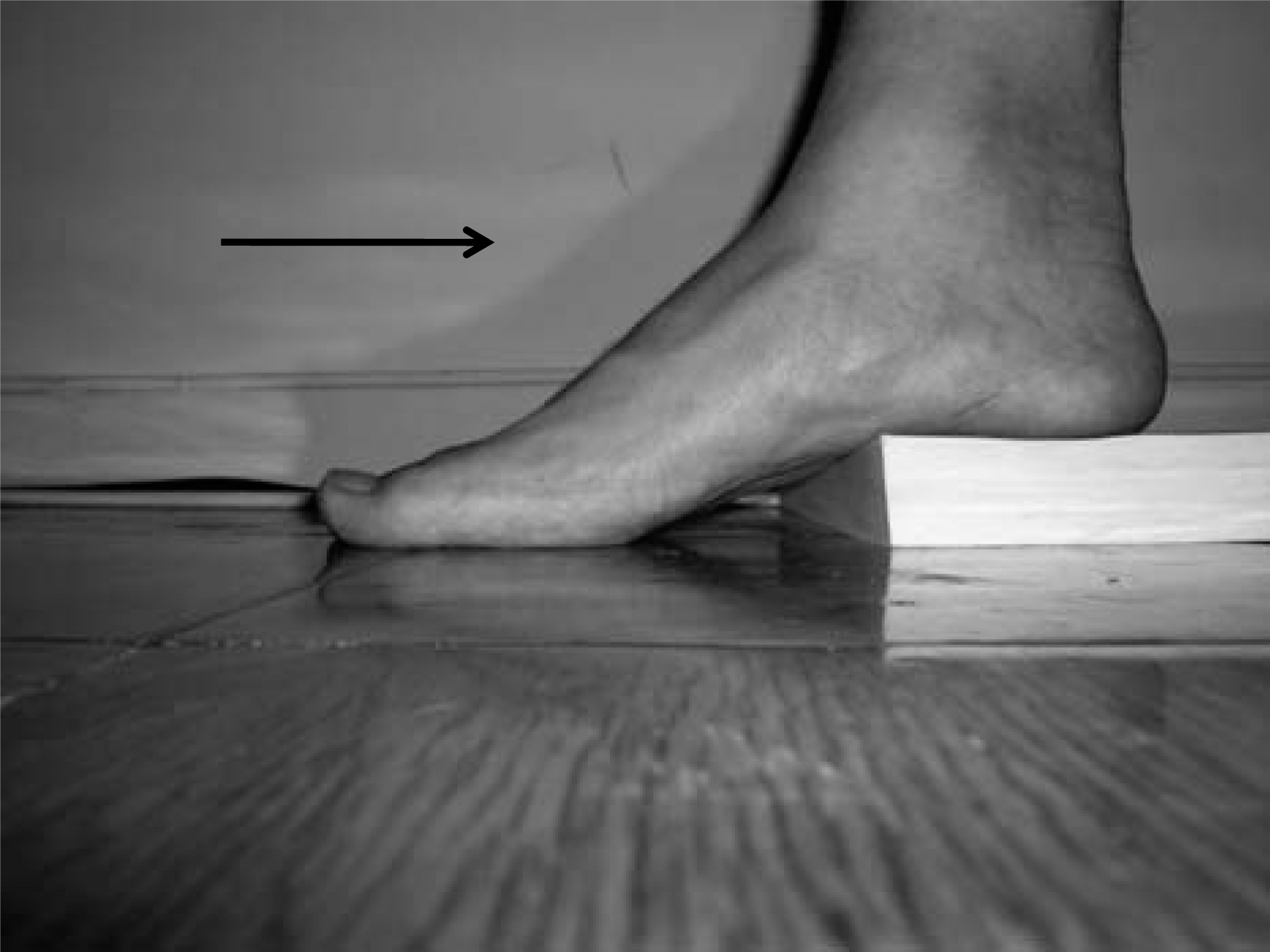
Obtaining the mortise hindfoot view in the office setting, using a heel block. The plantar position of the midfoot and forefoot relative to the hindfoot allows for an unobstructed mortise view of the hindfoot complex. The arrow indicates the direction of the X-ray beam.
In the operating room, fluoroscopy is used with the patient in the supine or prone position. Simulation of the weightbearing forces across the hindfoot and subtalar joint is accomplished by use of a Plexiglas (Rohm, Darmstadt, Germany) platform or an operative mallet. Either one of these devices is pushed against the plantar aspect of the heel in line with the tibia (Figure 2). In cases where displacement of fracture fragments may be of concern (i.e., calcaneus fractures), gentle pressure can be exerted that can still simulate the alignment that weightbearing forces will generate. We prefer the mallet as it is readily available.
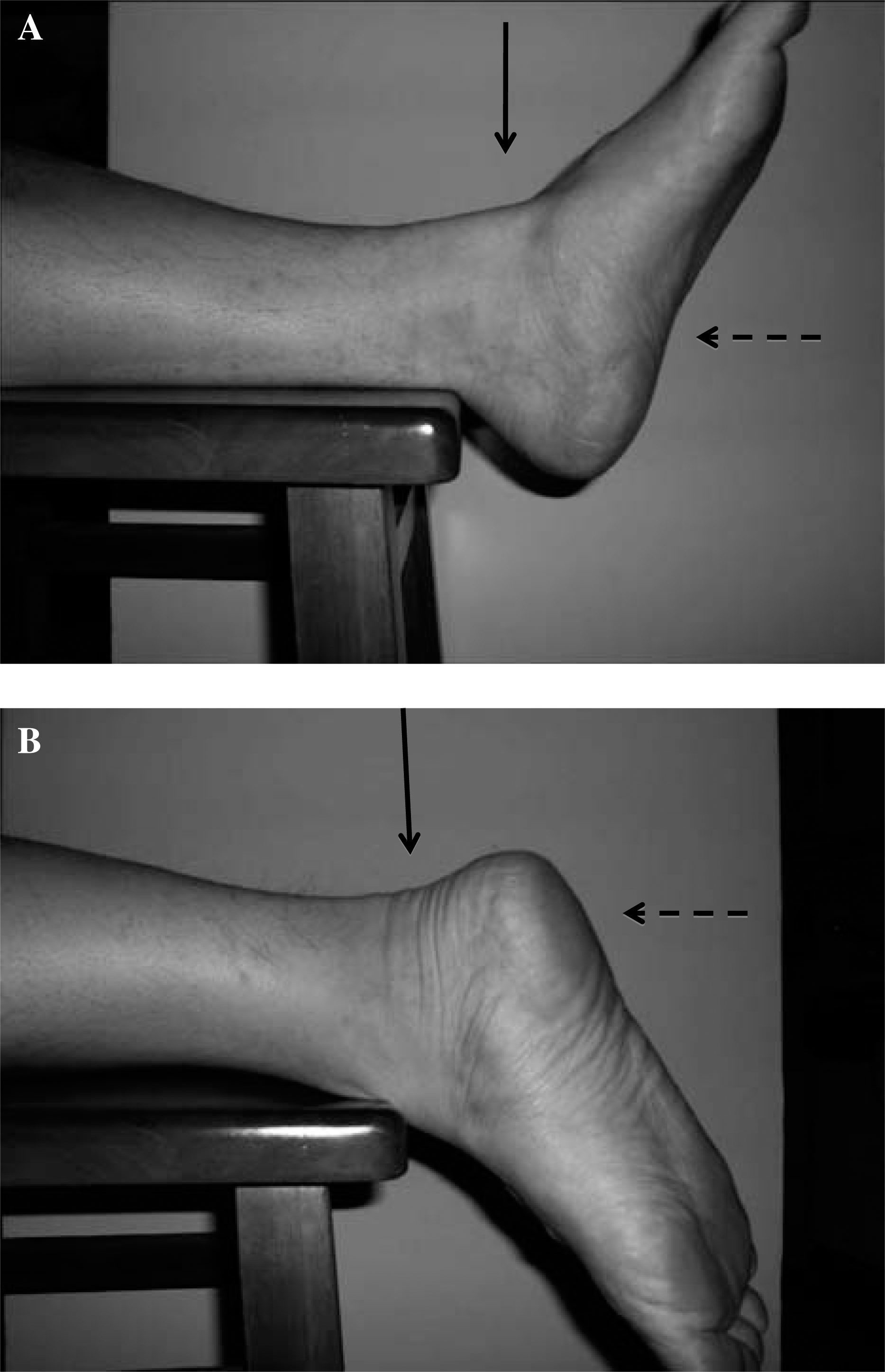
Obtaining the mortise hindfoot view intraoperatively, in the supine (A) and prone (B) positions. The plantar position of the midfoot and forefoot relative to the hindfoot allows for an unobstructed mortise view of the hindfoot complex. The solid arrows indicate the direction of the X-ray beam; the dashed arrows represent pseudo-weightbearing simulated forces across the hindfoot complex.
By either of these methods, a mortise view of the ankle joint is obtained with the forefoot and midfoot positioned plantarly relative to the hindfoot and ankle. Assessment of hindfoot alignment is determined by the position of the medial process of the posterior calcaneal tuberosity relative to the “plumb line” which is made perpendicular to the ankle and is collinear to the anatomic axis of the tibia. The plumb line simulates the mechanical axis of the lower extremity, and is the reference line to which hindfoot alignment is determined. The appropriate position of the plumb line is determined by the “reference line”, which is the line which bisects the base and body of the calcaneus and is perpendicular to the subtalar joint. The point radiographically where the reference line meets the tibial plafond determines the position of the plumb line (Figure 3).
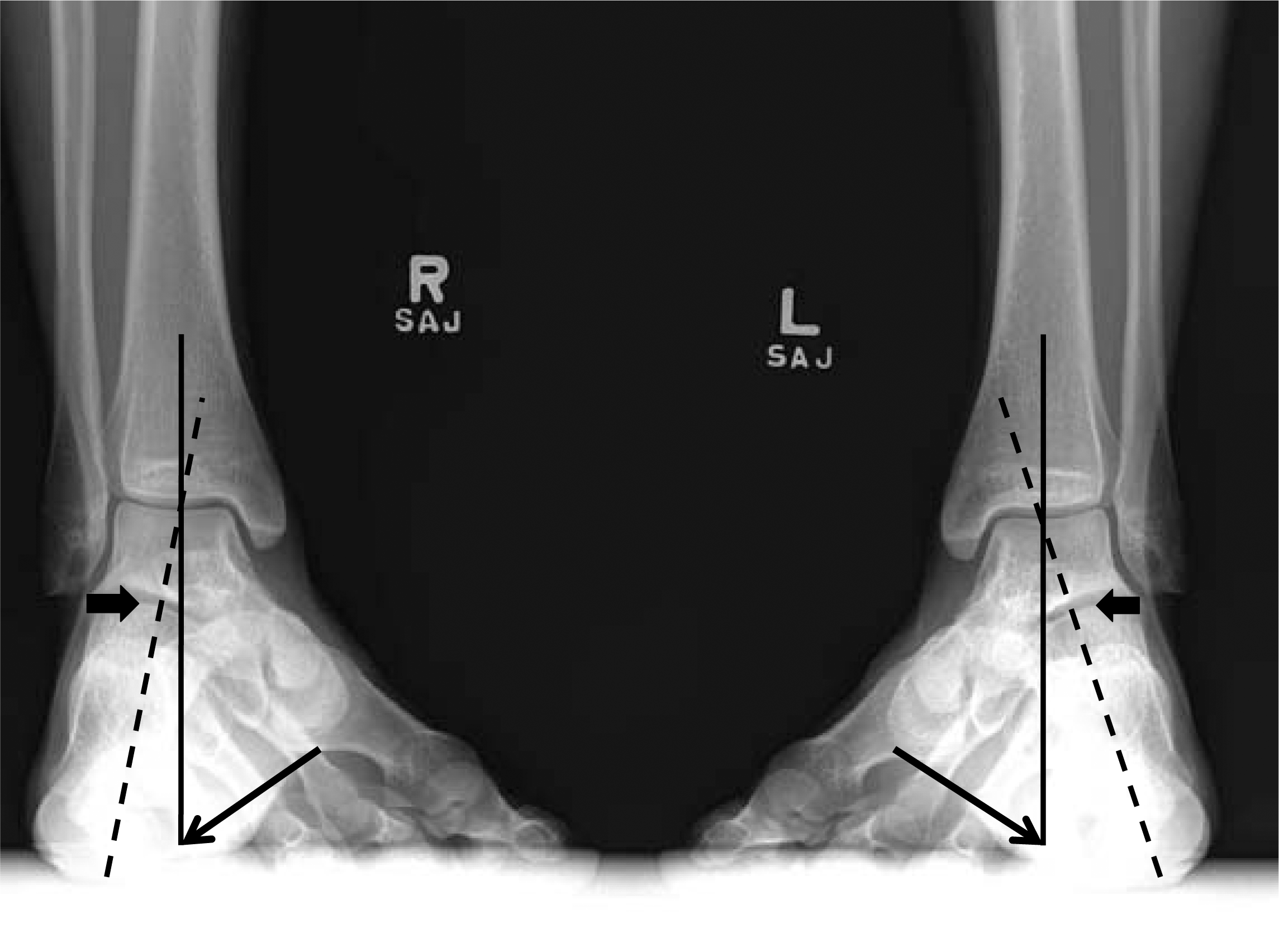
The mortise hindfoot view, demonstrating both hindfeet aligned in neutral; the medial process of the posterior calcaneal tuberosity is tangential to the plumb line (solid line) in both feet (indicated by the line arrows). The reference line (dashed line) bisects the calcaneal base and calcaneal body and is perpendicular to the subtalar joint (block arrows).
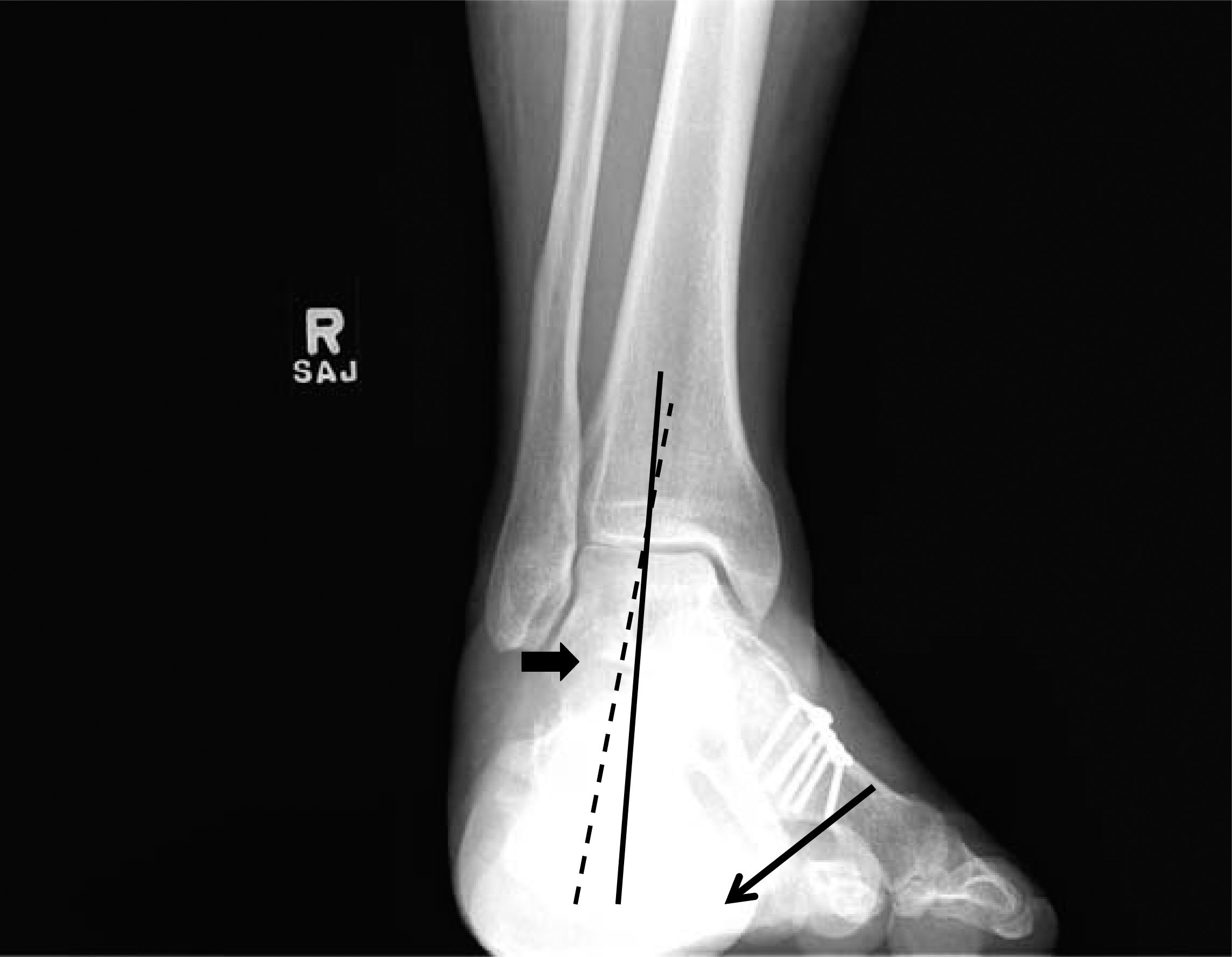
In neutral hindfoot alignment, the medial process of the posterior calcaneal tuberosity should be tangential to this line (Figure 3). If the medial process of the posterior calcaneal tuberosity is medial to this line, then the hindfoot is in varus (Figure 4); if lateral, valgus (Figure 5). An example demonstrating the correction of varus hindfoot alignment to neutral is shown radiographically in Figure 6. Clinically, the correction of the patient's varus hindfoot alignment to neutral was also appreciated.
The mortise hindfoot view, demonstrating a hindfoot aligned in varus; the medial process of the posterior calcaneal tuberosity is medial to the plumb line. Solid line, plumb line; dashed line, reference line; line arrow, medial process of the posterior calcaneal tuberosity; block arrow, subtalar joint.
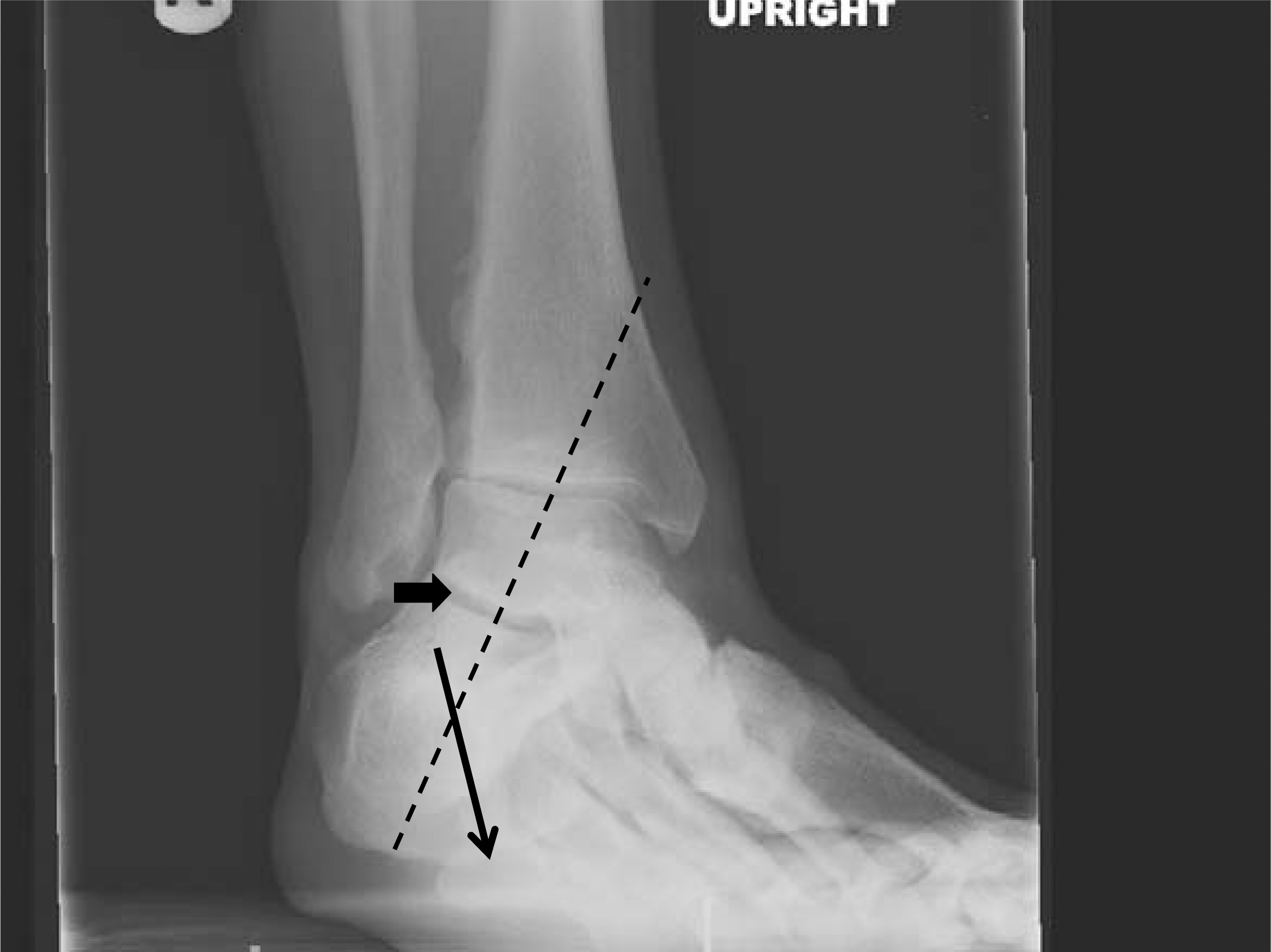
The mortise hindfoot view, demonstrating a hindfoot aligned in valgus; the medial process of the posterior calcaneal tuberosity is lateral to the plumb line. Solid line, plumb line; dashed line, reference line; line arrow, medial process of the posterior calcaneal tuberosity; block arrow, subtalar joint.
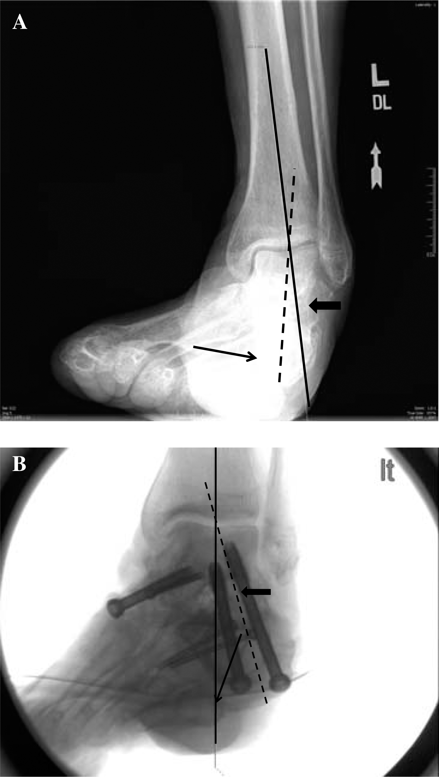
Clinical example of a varus hindfoot (A) corrected to neutral (B) with osteotomies and triple arthrodesis. Solid line, plumb line; dashed line, reference line; line arrow, medial process of the posterior calcaneal tuberosity; block arrow, subtalar joint.
DISCUSSION
Assessment of hindfoot alignment is crucial during treatment of associated pathologies to minimize pain, maximize functionality, and improve outcomes. Positioning of the subtalar joint into varus can generate a supinated forefoot and transfer weightbearing stresses abnormally along the lateral aspect of the foot and ankle. Similarly, valgus hindfoot alignment may lead to posterior tibial tendinopathies, gastrocsoleus contractures, arthritis of the lateral weightbearing surface of the tibiotalar joint, and medial metatarsalgia.
There have been numerous articles describing various methodologies for obtaining and assessing hindfoot alignment. Earlier techniques for studying the weightbearing heel were developed by Harris and Beath 3 and later refined by Kleiger and Mankin. 6 Their posterior tangential or suro-plantar views image the subtalar joint by having the patient stand on the cassette with the X-ray beam angled from behind at 45 degrees. However, because the beam is not perpendicular to the cassette, a distorted view of the calcaneus usually results, and an accurate assessment of subtalar function is not possible. 2 Furthermore, the techniques described by Kleiger are unable to demonstrate any change in the relative positions of the talus and the calcaneus with hindfoot inversion and eversion.
In response, Cobey described another method of assessing hindfoot alignment relative to the tibia.2,5 In his article, the hindfoot alignment view was obtained with the patient standing on an elevated platform with the X-ray beam posterior to the heel and angled 20 degrees caudal from the horizontal plane. The cassette was placed in front of the patient and oriented perpendicular to the beam (thus 20 degrees off the vertical plane). The midline of the calcaneus should normally lie lateral to the mid-diaphyseal axis of the tibia.
A variation of Cobey's method was used by Saltzman and El Khoury 7 , where the weightbearing axis of the leg (represented by the midlongitudinal axis of the tibia) was compared to a point on the most inferior aspect of the calcaneus. The perpendicular distance between this midlongitudinal axis of the tibia and the lowest calcaneal point was obtained and defined as the “apparent moment arm”. These values were given a positive sign if the weightbearing axis of the leg fell medial to the most inferior point on the calcaneus (valgus calcaneus) and a negative sign if the weightbearing axis fell lateral to the most inferior point (varus calcaneus). Saltzman's method differs from Cobey's in that the latter uses the calcaneal wall to define hindfoot alignment.
Variations in foot rotation, inconsistent bony landmarks, and beam positioning could lead to changes in measured hindfoot alignment using Cobey's technique. This concern led Johnson et al. to evaluate and develop a modified radiographic view where the standing patient must position their foot perpendicular to the cassette while maintaining the natural base of support. 4 Likewise, Saltzman and El Khoury's method 7 attempted to account for differences in hindfoot measurements that could arise from variations in the amount of foot rotation. Unlike Johnson et al.'s study, Saltzman found no differences in their apparent moment arm values with various foot rotation positions provided that they all assumed a standing natural position. This discrepancy was explained by the fact that both views rely on the posterior calcaneal anatomic landmark, which was unaffected by rotation. Therefore, correct anatomic referencing and/or proper foot rotational position are still prerequisites for obtaining a true coronal assessment of hindfoot alignment. While our view can be affected by the rotational position of the lower extremity, obtaining a precise mortise view (along with weightbearing) standardizes the landmarks that we use to determine hindfoot alignment.
Our technique addresses the concerns of Saltzman and Johnson by examining hindfoot alignment on a fixed radiographic position (the mortise view) and a fixed anatomic referencing point (the medial process of the posterior calcaneal tuberosity). The mortise view is easy to reproduce and familiar to most orthopaedic surgeons. Additionally, our technique also allows the clinician to evaluate the posterior facet of the calcaneus along the subtalar joint on the mortise view. This view becomes particularly helpful during operative fixation of an intraoperative calcaneus fracture, as the surgeon can note both intra-articular reduction and hindfoot alignment on one view.
While Cobey's hindfoot alignment view is an excellent method of assessing hindfoot positioning, and the methods by Saltzman and El Khoury and Johnson et al. are more accurate renditions of its predecessor, it does require a weightbearing patient to stand on a special mounting box to angle the radiographic plate. An alternative radiographic technique that obviates these two requirements is the long axial view. A line drawn on the vertical axis of the midbody of the calcaneus should be parallel and approximately one centimeter lateral to the mid-diaphyseal line of the tibia. 1 However, weightbearing is an important component in the determination of hindfoot alignment, as it eliminates any variability in measurements introduced by an unlocked subtalar joint. 7 Our technique can be obtained both in the standing and non-standing positions. While an accurate assessment of hindfoot alignment does require weightbearing forces across the subtalar joint, a sterile Plexiglas platform or a mallet can be used to simulate loading.
While the methods of Saltzman and El Khoury and Johnson et al. rely on a reproducible anatomic landmark (the posterior calcaneus), we rely on a reproducible radiographic positioning (the mortise view) to determine the hindfoot alignment. Furthermore, our technique is capable of demonstrating changes in the relative positions of the talus and the calcaneus with hindfoot inversion and eversion.