
Abstract
Due to the high rotational speed, the permanent magnet of surface-mounted high-speed permanent magnet generator is easily damaged by the centrifugal force. So a high strength alloy sheath is installed to protect the permanent magnet. The material, thickness and eddy current loss of the composite sheath of the high-speed permanent magnet generator with rotor strength constraint is studied thoroughly in this paper. Generator rotor strength under different limit conditions is calculated by numerical analysis method based on the thick-cylinder theory of elastic mechanics. Various methods have been used to reduce the eddy current. The composite sheath of high-speed permanent magnet generator on the basis of rotor strength constraint is presented. Change of the material, thickness of each layer of the sheath is determined by calculation of stress and eddy current loss and optimized design of composite sheath with reasonable stress distribution and lower eddy current loss. Strength test of prototype rotor is carried out.
Keywords
Introduction
High speed permanent magnet electrical machines are increasingly fasted in the industry due to their high-power density, compact size, high efficiency. Consequently, they are widely used in flywheel, aircraft engines, micro-turbine and so on [1,2]. Some rotor structures such as surface-mounted permanent magnet machines are easily damaged by the large centrifugal force because of the increase rotational speed. It often uses nonmagnetic alloy or carbon fiber sheath to protect permanent magnet [3].
In order to work in a safe mode, rotor strength analysis is an important part of the rotor design of a high speed PM machine [4]. Some authors have studied the properties of carbon-fiber sheath and permanent magnet block, the influence of filled blocks between magnetic poles, high temperature state and the analytical formulae for rotor strength was analyzed and the analytical solution was validated by the finite element method [5,6]. Although carbon-fiber sheath has a high strength to weight ratio and low electrical conductivity which lead to very low eddy-current loss, the thermal conductivity of the carbon-fiber material is very low that makes the cooling of the magnet very difficult, which may cause irreversible demagnetization of magnets [7]. A high-speed permanent magnet generator can be made much smaller at the same power level but it is difficult to cool machine. Many authors have studied the properties of nonmagnetic alloy sheath because of alloys have much better thermal conductivity [8–10]. But the higher electrical conductivity of all alloys sheath usually leads to much higher eddy-current loss by the space harmonics and time harmonics [11]. Therefore, it is necessary to find out the effective measures to reduce the rotor eddy current loss. Segmenting circumferential or axial grooving sheath, segmenting PM can split eddy current path [12,13]. Optimizing air gap length, special magnetization patterns and small slot openings of the stator core can reduce air gap harmonics [14–16]. Another method is added a copper shield between the sheath and magnet [17–19].
In recent years, a hybrid sheath such as composed alloy and carbon fiber, composed carbon fibre and glass fibre are presented and analyzed [20–22]. Most of these studies are either focused on rotor strength analysis or reducing eddy-current loss individually. It is lack of an integrated and comprehensive study in the area. Therefore, it is necessary to carry out a fundamental study to find out an optimized solution. In this paper, a 1.8 kW, 60000 rpm high-speed permanent magnet generator (HSPMG) is designed and under development. The rotor strength of the HSPMG is studied under extreme conditions using the theory of thick-walled cylinders of elastic mechanics, including integrated thickness, material and temperature. With strength as a constraint, a simple composite sheath topology is proposed to reduce the rotor eddy current loss.
Methodology
Subsection
Prototype design: structure and parameters
A prototype HSPMG is designed and its structure is shown in Fig. 1. The stator of the prototype is manufactured with 0.2 mm silicon steel sheet. The rotor has two poles and some surface-mounted permanent magnets that has a ring structure. The interference fit exists between the nonmagnetic alloy sheath and the permanent magnet, the inherent stress to counteract the centrifugal forces on permanent magnet. However, the interference fit is increasing with rotating speed and the yield stress of sheath material is restricted. Because the thermal expansion coefficient of permanent magnet material and sheath material is different from each other, an appropriate interference fit is required to make both maximum PM stress and the maximum sheath stress under the permitted value. The design parameters of the prototype are shown in Table 1.
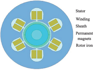
Illustration prototype of generator structure.
Design parameters of the prototype
The traditional double-sided mover of the PMLSM for an electromagnetic launcher is composed of a yoke plate and permanent magnets with their N and S poles arranged alternately. To obtain a higher acceleration under the same electromagnetic thrust, a new DSMM-R-PMLSM mover structure is proposed, as shown in Fig. 2. This structure employs an aluminum-alloy plate of low density to support of the whole movement part, and permanent magnets are fixed on both sides of this plate. In order to close the magnetic-flux loop, two auxiliary stators made of silicon steel sheets are added to each side of the double-sided mover. The width of the auxiliary stator is the same as the height of the main stator yoke.
For surface permanent magnet, the PM thickness is related to the sheath thickness by:
The rotor strength is analyzed by 3D finite element method. The interference between the sheath and the permanent magnet is 0.008 mm. The 3D illustration of prototype of rotor structure and rotor material properties is shown in Fig. 2 and Table 2.
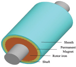
Illustration of prototype of rotor structure.
Rotor material properties
A stress model of the cylinder structure of PM and sheath is set up, which is a simplified planar stress model.
According to the theory of elastic mechanics, when the axial strain is ignored, the equilibrium equation of rotating cylinder is:
Considering the effect of temperature rise of the rotor, the relationship between strain and stress can be expressed as:
Where ϵ r and ϵθ denote radial strain and tangential strain, 𝛽 is thermal expansion coefficient of the materials, ΔT is the temperature difference. E is the material Young’s modulus, 𝜐 is the material Poisson ratio.
The geometric equation is:
The material properties of the prototype rotor are shown in Table 2. According to the rotor mechanical strength design criteria and the rotor material properties, assumptions are made as follows:
(1) The maximum Von-Mises stress of the nonmagnetic alloy sheath is less than the yield stress of the material;
(2) The maximum tensile stress of the permanent magnet is less than the yield stress of the material;
(3) Displacement between rotating shaft and permanent magnet are equal;
(4) The expansion displacement of the shaft is not considered.
The boundary included in the radial stress of PM and the sheath equations are:
In order to verify the validity of the reliability of rotor, a prototype generator is manufactured. The stress experimental operating platform is shown in Fig. 3.
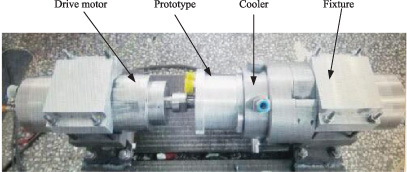
Stress test operating platform.
The strength of high-speed permanent magnet generator rotor is related to static interference, speed, temperature, thickness of permanent magnet and sheath, material and operating conditions. With the increase of speed, centrifugal force increases gradually, and permanent magnet materials are vulnerable to damage in this process. In the process of starting the motor, when the rated speed is reached cold state (the speed of 60000 r/min and the operation temperature of 22 °C) from static state (the speed of 0 r/min and the operation temperature of 22 °C), the permanent magnet has under large tangential stress; in the process of the motor reaching steady state (the speed of 60000 r/min and the operation temperature of 160 °C), the temperature rise of the motor increases continuously, and the permanent magnet is very easy to lose its magnetism. In this paper, based on the finite element method, the strength of the rotor is calculated under static, cold and limit steady state respectively, which 160 °C is set as the steady thermal limit condition for convenience of calculation.
Stress distribution of static state (the speed of 0 r/min and the operation temperature of 22 °C)
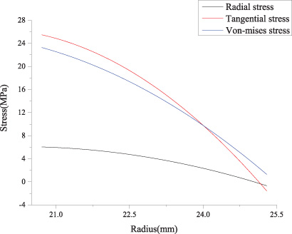
Figure 4 shows the Stress distribution cloud-picture of sheath and permanent magnet under static state. Figure 5 shows the stress distribution of sheath under static state. Figure 6 shows the stress distribution of permanent magnet of static state.
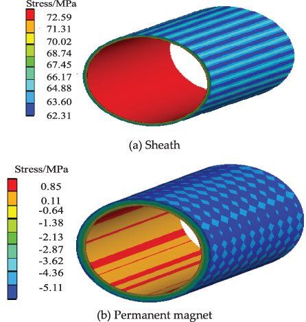
Stress distribution cloud-picture of sheath and permanent magnet under static state.
Stress distribution of sheath under static state.
Stress distribution of permanent magnet under static state.
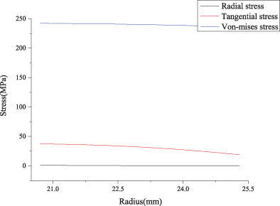
From the figures, it can be seen that the maximum Von-Mises stress of the sheath is 72.596 MPa and the largest stress is in the sheath inner diameter. The radial stress and tangential stress of the permanent magnet are less than zero, the PM is in compression. With the decrease of the thickness of the permanent magnet and sheath, the stress distribution of the sheath and the permanent magnet decreases.
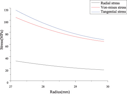
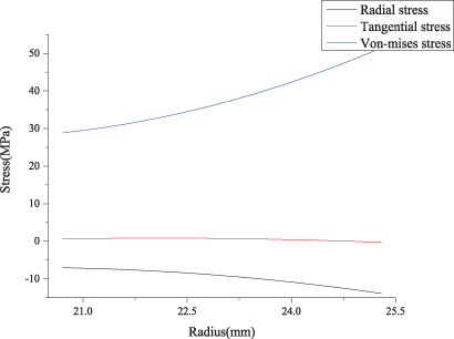
Figure 7 shows the stress distribution cloud-picture under cold state running. Figure 8 shows the stress distribution of sheath under cold state running. Figure 9 shows the stress distribution of permanent magnet under cold state running.
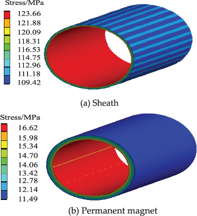
Stress distribution cloud-picture of sheath and permanent magnet.

Stress distribution of sheath under cold state running.
Stress distribution of permanent magnet under cold state running.
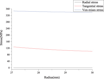
As can be seen from these figures, compared with static state, the equivalent Von-Mises stress of the sheath increases with the increase of rotating speed. The maximum stress is also at the inner diameter of the sheath, the value is 123.66 MPa and is less than the yield stress of the material. At the speed of 60000 r/min, the interference between the sheath and the permanent magnet decreases, so the contact pressure decreases. It shows that tangential stress of the permanent magnet is tensile stress, the highest is 16.623 MPa, and it is also lower than the yield stress of the material.
Stress distribution cloud-picture of sheath and permanent magnet under high temperature state running.
Stress distribution of sheath under high temperature state running.
Stress distribution of permanent magnet under high temperature state running.
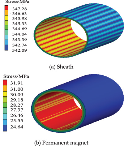
Figure 10 shows the stress distribution cloud-picture under high temperature state running. Figure 11 shows the stress distribution of sheath under high temperature state running. Figure 12 shows the stress distribution of permanent magnet under high temperature state running.
Considering the constraints of temperature on permanent magnet, 160 °C is taken as the extreme operation temperature. From Figs 10 to 12, the influence of temperature on the tangential stress and Von-Mises stress of permanent magnet and sheath are obvious. In the figures the maximum equivalent Von-Mises stress of the sheath is 347.28 MPa, the maximum tangential stress of the permanent magnet is 31.913 MPa. Because the coefficient of thermal expansion is different, it causes the contact pressure between the sheath and the permanent magnet to increase.
Under all conditions, the influence of the radial stress of permanent magnet and sheath are not obvious. Both with the rotating speed and temperature increase, the tangential stress and Von-Mises stress of PM and sheath gradually increases. When the temperature varies from 22 °C to 160 °C, the rotating speed varies from 0 to 60000 r/min, the tangential stress of PM increases from −5.11 MPa to 31.91 MPa, the Von-Mises stress of the sheath increasing from 62.31 MPa to 347.28 MPa, and the radial stress change is very small.
Based on the above FEM analysis, a rotor with composite sheath is designed in order to reduce the eddy current loss with rotor strength constraint. Nonmagnetic alloy sheath is normally used to protect permanent magnet and the sheath thickness is inversely proportional to eddy current loss because the eddy current loss in the rotor increases with the growing of sheath thickness [22]. Further FEM analysis was carried out to evaluate the effect of composite sheath added to the rotor.
Generally high-speed permanent magnet generator has a larger effective air gap because of lowering stator core loss, so air gap flux density usually set to be about 0.5 T. Considering electromagnetic design, nonmagnetic alloy sheath thickness limited by the air-gap flux density, thickness of PM and air gap length. If larger the thickness of the nonmagnetic alloy sheath, the magnetic resistance of the main magnetic circuit of the motor increases in the sheath, causing the operating point of the permanent magnet to decrease, and the lower the excitation effect and the decrease of the output flux.
The composite sheath is designed with the strength of the rotor as the constraint, and the eddy current loss of the rotor is reduced as much as possible on the premise of guaranteeing the strength. Sheath thickness of surface mounted high-speed permanent magnet motor is estimated by the following formula:
According to the theory of combined thick-walled cylinder, the composite sheath is divided into bilayer and they are assembled together by interference fit. If their maximum stresses are the same, the composite sheath becomes thinner than the original. Consider the process, the original sheath of 1 mm was reduced by 20%. Different materials and thicknesses are given respectively, the different composite sheath and the maximum equivalent Von-Mises stress of the sheath is shown in Table 3.
Von-Mises stress of composite sheath
Any case in Table 3 can not achieve the unity of the strength of inner and outer sheath, and the sheath strength of different materials is not unified, it may damage the sheath because of the material difference. Base on elastic mechanics unified strength theory, if the inner and outer layers are different materials and when the stratified radius is (r
o
∕r
i
)1∕(n+1) (n is number of layers), composite sheath strength will be unified. If the inner and outer layers are the same materials, When the stratified radius is
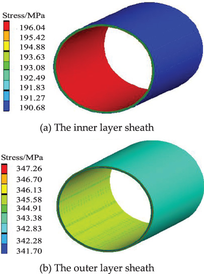
Von-Mises stress cloud-picture of the same material composite sheath.
Figure 13 shows that the strength of Ti6A14V composite sheath is unified, which is far less than the original sheath strength, the layer would be damaged. The bilayer Inconel718 composite sheath is closer to the original sheath strength, when the rotating speed and temperature change. It can be seen as a unified sheath. Moreover, the stress distribution is more evenly. The bilayer Inconel 718 composite sheath that the inner layer should have the same value as the outer layer is optimal scheme.
Two kinds of rotor eddy current loss is calculated in the 3D model by finite element method. The distribution cloud-picture of rotor eddy current density of original sheath and composite sheath are shown in Figure 14.
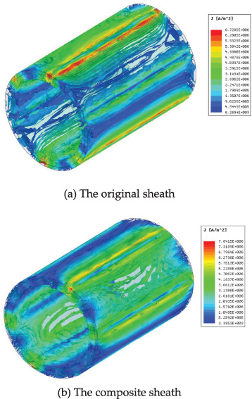
Eddy current density distribution cloud-picture of rotor sheath and composite sheath.
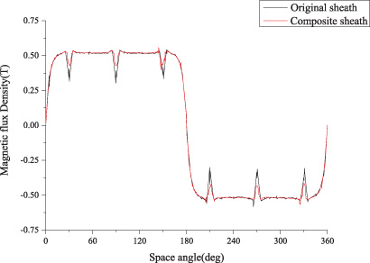
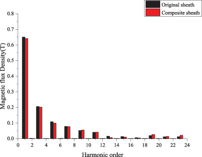
It can be found from Figure 14, the composite sheath rotor eddy current density smaller than that of single layer. After the thickness of the sheath is reduced, the magnetic resistance of the main magnetic circuit decreases, which lead to the operating point of the permanent magnet and the flux of the main magnetic circuit increase, thus the space harmonics of air gap decrease. Two kinds of the air gap flux density waveform and FFT are shown in Fig. 15 and Fig. 16.
Air gap flux density waveform of two kinds of sheath.
FFT results of the air gap flux density of two kinds of sheath.
Figure 15 shows that the air gap flux density of two kinds of sheath are almost the same excluding parts of waveform distortion. Figure 16 shows that the main of harmonic orders are reduced in the composite sheath generator.
The main loss and efficiency of two kinds of rotor generator are shown in Table 4.
Main loss and efficiency of generator
Due to the air gap harmonics decrease, the stator core loss is decreased by 9.2 W, compared to the original sheath; and the eddy current loss is reduced by 10.2 W. Meanwhile the generator efficiency is increased by 1.1%, which is beneficial to the heat dissipation of the generator.
Based on the outcomes from the above analytic study, an experiment is carried out on the platform (in Fig. 3), the results of comparison of experimental data are shown in Table 5.
Comparison of experimental data
Comparison of experimental data
According to the Table 5, the high-speed generators are driven by a high-speed motor, the test results show that both rotors can operate safely at rated speed.
From the study, the following conclusions can be drawn:
Firstly, based on the thick wall rotating cylinder theory of elastic mechanics, rotor strength is analyzed in different extreme working condition. The result shows that with the rotating speed and temperature increase, both tangential stress and Von-Mises stress of the permanent magnet and sheath change largely. Because of the coefficient of thermal expansion difference, the influence of temperature are obvious apart from radial stress.
Secondly, based on the combined thick wall cylinder theory of elastic mechanics, it is found that the rotor strength is very close to both sheath when the composite sheath average divided into 0.4 mm with same materials.
Finally, with rotor strength constraint, the thickness of sheath decreases by 20%, the rotor eddy current loss decreases 10.1 W, and the stator core loss is decreased by 9.1 W. The generator efficiency is increased by 1.08%. The composite sheath is beneficial to heat dissipation of the generator.