






Abstract
In this paper, a high-energy density electromagnetic buffer (EMB) is studied and analysed for the violent acceleration and high velocity of intensive impact loads. First, the design requirements of the EMB are proposed to select reasonable structure and magnetic circuit parameters. The equivalent current model is used to introduce the primary eddy current affected by demagnetization effect and the induced secondary eddy current. The magnetization process is studied by dividing the conductor tube into the approach end and the departure end. Considering the nonlinear damping and eddy current interaction between primary and secondary, a primary-secondary eddy current loss coupled nonlinear time-step finite element model (FEM) is established to obtain the spatiotemporal distribution characteristics of eddy current. Finally, a test experiment with weak impact, medium impact and intensive impact was carried out. The measured displacement, velocity, damping force, and time nodes responses during buffering are consistent with the established time-step FEM results. The proposed high-energy density EMB can effectively complete the impact buffering process. It is reasonable to obtain the eddy current loss and its magnetization law from the established FEM which is suitable for shock buffering with different impulse strength.
Introduction
The concept of eddy currents has been investigated by many researchers for different uses of dynamic systems, such as vibration suppression, braking systems, since the late 1800s [1]. There are two ways to generate eddy currents. They are generated either by the motional electromotive force since the movement of the conductor in a static magnetic field or induced electromotive force due to the conductor being in a time-dependant magnetic field [2].
The interaction of the induced magnetic field because of eddy currents and the external magnetic field causes a braking force [3–5], called as eddy current damping, against the relative motion. For damping applications, the electromagnetic buffers (EMBs) produce damping forces without contact different from almost any other passive damping mechanisms [6–8]. Since there is no additional stiffness and friction, this is advantageous as the EMB introduces little or no impact on the dynamic response of the overall system [9]. Nowadays, many researchers have carried out detailed research on the eddy current loss, magnetic field distribution and damping characteristics of the permanent magnet EMB.
Edwards et al. [10] investigated the analytic model of the eddy current distribution and braking force of the permanent magnet linear EMB, together with an approximate treatment of end effects, based on an equivalent volume current representation of the permanent magnets and the stratification theory. J. Jang et al. [11,12] introduced the two-dimensional analytical model of permanent magnet array linear EMB, and compared the air-gap magnetic field and the eddy current with magnetic field velocity of Halbach magnetization, horizontal magnetization and vertical magnetization. According to the Biot–Savart law, Bae et al. [13] derived the expression of eddy current density and air-gap magnetic density of the permanent magnet cylindrical linear EMB without considering the surface current. However, the armature reaction and skin effect caused by eddy current are not taken into account. Ebrahimi et al. [14–16] obtained the eddy current distribution and braking force of the conductor tube under the premise of considering the skin effect and the eddy current boundary effect, which verified the accuracy of the low speed model. But the armature reaction is still ignored. Lee and Park introduced the magnetic Reynolds number into the rotating permanent magnet EMB to study the armature reaction caused by the eddy current magnetic field, but the calculation of the eddy current still does not consider the influence of the eddy current magnetic field [17–19]. Additionally, EMBs have been widely used in vibration control [20,21], magnetic levitation [22,23], aerospace [24] and other fields. The eddy current distribution law is analysed by equivalent volume current method and stratification theory, and the like.
For the velocities in the past range of engineering applications, damping force is proportional to the velocity of the permeant magnetic source, which is expressed as viscous force [25]. However, the intensive impact load still exists in the fields of impact, non-contact impact of submarines, landing of space shuttles, etc. The generated violent acceleration and high velocity will cause distortion of the spatiotemporal distribution of the eddy current loss in the conductor. Generally speaking, in the past, there were few studies on the magnetization of eddy currents, and the relationship between eddy current and magnetization under intensive impact load was not established. At the same time, the eddy currents in the EMB are not all advantageous. The eddy currents of the permanent magnet and the iron pole have non-negligible effect on the damping characteristics.
This article aims to explore the spatiotemporal distribution of the eddy current loss and its magnetization effect of various parts under strong impact load by introducing a permanent magnet cylindrical EMB. The accuracy of the established finite element model (FEM) and the reliability of the results were verified by three shock experiments.
Electromagnetic damping
EMB design requirements
Effective buffering for the violent acceleration and high velocity can significantly improve reliability and life of the EMB. Therefore, the design considerations at this time are to increase energy consumption density, damping force peak and critical velocity. The cylindrical structure is effective in reducing magnetic leakage without lateral end effects. The usage of NdFeB permanent magnets can avoid power supply requirements of the working magnetic field and failure after electrical outage.
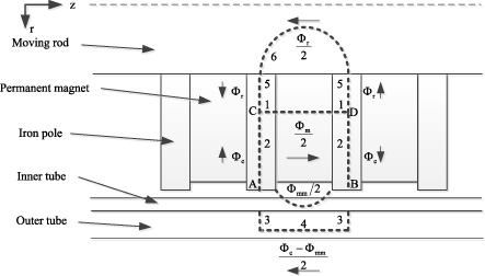
Partial schema of the studied EMB and the equivalent magnetic circuit.
Figure 1 illustrates the partial two-dimensional half-section structural schematic about the axis of symmetry z of the permanent magnet cylindrical linear EMB. The studied EMB mainly consists of two parts: (1) the primary part, which consists of a moving rod combined with a sequence of ring-shaped, axially magnetized permanent magnets separated by pure iron poles, and (2) the secondary part, which consists of an outer tube and an inner tube. The primary and secondary relative motion occurs under the intensive impact load, which causes the induction of the eddy currents in the outer tube and inner tube. According to the Lorentz force law, eddy currents produce a magnetic flux that opposes the external magnetic flux density, resulting in a damping force. There are many ways to arrange permanent magnets. Document [15] demonstrates that the axial arrangement increases the damping coefficient by three times as much compared with that of the radial arrangement. With the N–S pole adjacent arrangement, most of the magnetic field lines does not enter the conductor tube through the air-gap. Once iron with sufficient thickness is inserted between the permanent magnets of the same polarity facing each other, the two sides of the iron are magnetized respectively. The magnetic field lines are squeezed into the conductor by the iron. The iron pole and the permanent magnet are attached together by the generated magnetic force. Air-gap is an important parameter for the improvement of damping force. The smaller the air-gap, the larger the air-gap magnetic field and damping force will be obtained. However, it is very difficult to process composite thin-walled long tube with small air-gap. Therefore, the value of the air gap is 0.5 mm. In order to obtain a reasonable air-gap magnetic field, in addition to reducing the air-gap, the effect of other buffer parameters is also necessary to explore through magnetic circuit analysis.
The purpose of the structural design is to obtain an effective magnetic circuit with high magnetic field flux utilization under the volume limitation. According to the equivalent magnetic circuit of the EMB shown in Fig. 1 and the Kirchhoff’s law of magnetic potential difference, the magnetic circuit relationship can be obtained as
By solving Eq. (1) to Eq. (7), the magnetomotive force between points A and B is given by
Therefore, the gap magnetic density including the magnetic flux leakage and the eddy current magnetic field is expressed as
Equation (10) is transformed to obtain the following expression
It is observed that increasing the magnetomotive force of the permanent magnet, weakening magnetomotive force of the eddy currents, and reducing the thickness of the iron pole can effectively enhance the air-gap flux density. Obviously, reducing the reluctance of the second to fourth segments, the air-gap, the conductor tube, and improving the reluctance of the fifth and sixth segments and the permanent magnets can also heighten the magnetic flux density. It is worth noting that increasing the reluctance of the permanent magnet, that is, improving rate permeance of the external magnetic circuit, leads to an increase in the slope of the load line and the working point then the magnetic flux density.
As shown in Fig. 2, r i , r o , r d , R i , R o , C a are the internal radius of the inner cylinder, the external radius of the inner cylinder (the internal radius of the outer cylinder), the external radius of the EMB, the internal radius of the permanent magnet, the external radius of the permanent magnet, integral path for solving eddy current magnetic field, respectively. The thick bold arrow indicates the direction of the field line inside the ring-shaped permanent magnet.
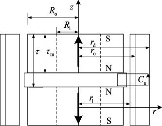
Configuration of the primary and secondary.
In the electromagnetic buffering process at low velocity, the secondary eddy current can be assumed to be generated by permanent magnets at quiescent point. First, the equivalent magnetic volume current density and equivalent surface current density proposed by Furlani [26] can be used to replace a cylindrical permanent magnet.
The radial component of the net flux density at (r, z) is calculated by Craik [27] as follows:
The net magnetic induction radial component of the ring permanent magnet B
02 can be expressed as the flux density difference of two cylindrical permanent magnets with outer radii R
o
and R
i
. The net flux density radial component produced by the upper and lower ring permanent magnets at (r, z) can be simplified as the sum of the flux densities at (r, z) and (r, τ − z), and is defined as B
0.
The motional electromotive force and eddy currents are generated in the conductor moving in the constant magnetic field. With the continuous action of the intensive impact load, the weakening effect of the eddy current field on the original field is gradually enhanced, that is, the demagnetization effect. Therefore, the magnetic induction of induced eddy current in the conductor tube is obtained by using the Ampere circuital theorem for the loop C
a
in Fig. 2.
The eddy currents surround the conductor tube in an annular manner. The induced magnetic field on the primary magnetic field is different at different positions. Therefore, a magnetic Reynolds number (R
m1) with a correction coefficient is proposed to estimate the net magnetic induction as follows
High-velocity also results in the skin effect at the edge of the conductor tube. The eddy currents are essentially alternating current induced by a traveling wave field in the secondary generated by permanent magnets. The current density at the surface of the conductor tube is stronger than that of tube body, and the penetration depth is used to indicate this non-uniformity. The penetration depth is defined as the depth below the conductor surface at which the current density decreases to 1∕e of the current density at the surface, which is obtained from
The eddy current frequency is the ratio of the traveling wave field velocity to the same pole spacing. The penetration depth is inversely proportional to the conductivity and the permeability of the conductor tube. The current density in a conductor tube decreases exponentially with depth d from the surface, which is modified to accommodate the skin effect, represented by
Since the induced magnetic field of the eddy currents acts on the primary during the buffering process, eddy current losses still occur in the permanent magnet and the iron pole. The induced electromotive force can be calculated by the third Maxwell’s equation (Faraday’s law).
The coupling process of the eddy current magnetic field of the outer tube and the axial magnetization field generated by the single permanent magnet is mainly divided into three stages: the axial magnetization field enters, undergoes and exits the outer tube, respectively. The outer tube on both sides of the iron pole is divided into two parts: the approach end and the departure end.
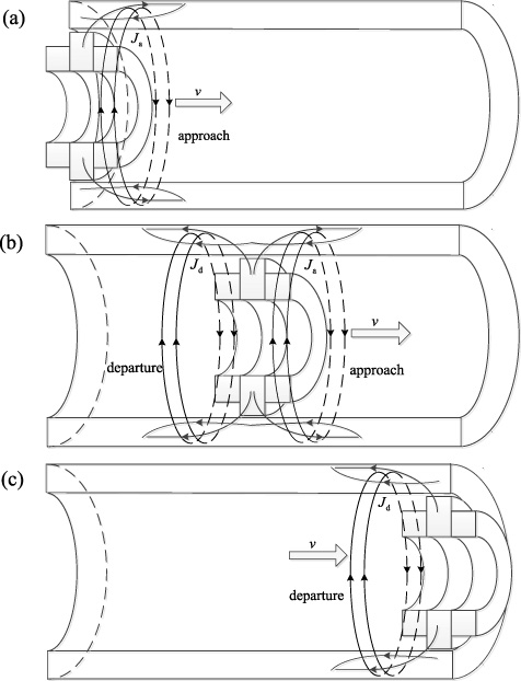
Principle of eddy current magnetization at (a) tube head, (b) tube body, (c) tube tail.
In the process of the axial magnetization field entering the outer cylinder, first, the approach end is coupled with the axial magnetization field. According to Lenz’s law, the direction of the eddy current field in the approach end is opposite to that of the axial magnetization field. This weakens the axial magnetization field and produces the demagnetization effect, so that the degree of magnetization of the outer cylinder is reduced, as observed in Fig. 3(a). As the permanent magnet undergoes the outer tube, the tube body is coupled to the axial magnetization field. The flux of the axial magnetization field generated by the permanent magnet passes through the iron pole to enter both the approach end and the departure end. In these two ends, eddy currents of the same direction are generated. The direction of original axial magnetization field is opposite to that of the eddy current field in the approach end and the same as that of the eddy current field in the departure end. As a result, the degree of magnetization is reduced in the approach end, and increased in the departure end, as demonstrated in Fig. 3(b). When the permanent magnet moves to the tail of the tube, the direction of the eddy current magnetic field induced only in the departure end is the same as that of the axial magnetization field, so that the degree of magnetization increases, as illustrated in Fig. 3(c).
For the real simulation of the buffering mechanism of intensive impact loads, a nonlinear time-step FEM considering the coupling of primary-secondary eddy current loss is established. In view of the fact that the EMB studied is of the plurality of rotating bodies, the cylindrical about z solution in the 2D module of the low-frequency electromagnetic field software Ansoft Maxwell is selected.
The corresponding simplification is made for the finite element analysis model that the connection between the inner cylinder and the outer cylinder with less influence on magnetic field be ignored. The inner cylinder and the outer cylinder are fixedly connected. And between the moving rod and the iron pole, the iron pole and the magnet are rigid body contact connection. Combining the physical model of the EMB with the FEM requires adding boundary conditions to the edges of the solution domain:
In order to study the characteristics of eddy current spatiotemporal distribution under intensive impact load, three different impact loads with the peaks of 610 kN, 1015 kN and 2701 kN act on the primary of the EMB, as shown in Fig. 5. The EMB not only relies on the damping force for braking, but also the recuperator force shown in Fig. 6 is applied. The recuperator force can be calculated as:
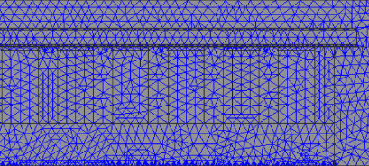
EMB mesh.
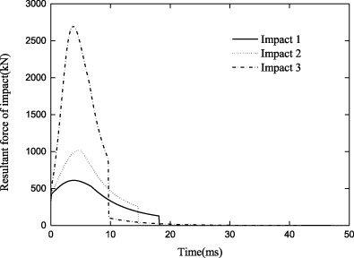
Different test impact loads.
The solid line in Fig. 7 shows the demagnetization curve of the NdFeB used in the impact testing and simulation analysis with the test temperature of 10 °C to 15 °C. The sintered NdFeB permanent magnet was selected, which has high remanence and high energy product. The coercive force and remanence of NdFeB is a function of temperature. Therefore, the coercive force is 11.43 kOe, and the remanence value is 1.48 T considering the test temperature. Considering that the maximum acceleration of the EMB is as high as 2360 m/s2, the induced eddy current in the primary generated by the secondary eddy current field cannot be ignored. The conductivity of the NdFeB is set to the common value of 625000 s/m.
The permanent magnet operation point is in the second or third quadrant when the buffer occurs. With the application of the intensive impact load, the remanence is moved from the quiescent operation point to the dynamic operation point along the demagnetization curve due to the eddy current demagnetizing field, as denoted Fig. 7. There is a knee point in the demagnetization curve. With the operation point above the knee point, the permanent magnet will reversibly demagnetize, which is the position where the EMB is expected to work. With the operation point below the knee point, the permanent magnet will be partially irreversibly demagnetized.
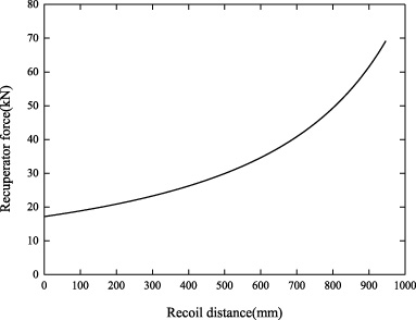
Recuperator force.
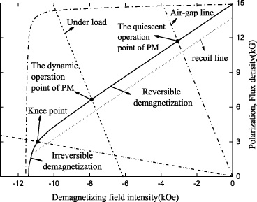
Demagnetization curve of NdFeB.
If the reverse eddy current field applied to the permanent magnet is removed, the permanent magnet can still maintain a certain remanence which moves along the recoil line. Figure 7 reflects that the new remanence is less than that with weak external magnetic field. This loss of remanence is usually irreversible. In fact, the recoil line is a narrower loop, which is replaced by the straight line. The permeability of NdFeB permanent magnets conforms to the demagnetization curve:
Ferromagnetic materials play a vital role in field guidance and eddy current generation. The permeability of ferromagnetic material is a nonlinear function of magnetic field intensity. The magnetic saturation of the iron pole and the outer tube under the primary field and the induced field must be fully considered to obtain a reasonable eddy current spatiotemporal distribution. The magnetization relationship of the iron pole and the outer cylinder is given in Fig. 8. a 2 is the knee point and a 3 is the saturation point. In the a 1 a 2 segment, the permeability increases continuously, resulting in the fastest increase in magnetic induction. In the a 2 a 3 segment, the permeability begins to decrease, accompanied by an increase in magnetic induction. After the external magnetic field strength increases to point a 3, the growth rate of the magnetic induction intensity corresponds to it in the air, which is called magnetic saturation.
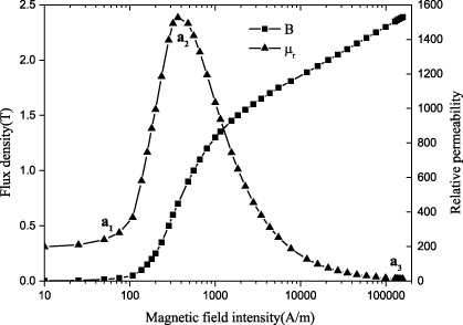
Magnetization relationship of iron pole and outer tube.
For the numerical analysis of the established FEM, we obtain the spatiotemporal distribution of the EMB eddy current and its magnetization under the intensive impact load 3.
Secondary eddy current distribution and magnetization
The inner tube is the largest component of the eddy current loss and the resulting damping force. The spatiotemporal distribution of the eddy current loss in the inner tube is obtained by the net field formed by the primary magnetization field and the eddy current field.
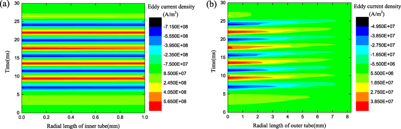
The spatiotemporal distribution of the secondary eddy current in (a) inner tube and (b) outer tube.
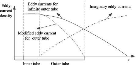
Eddy current of the inner tube and outer tube.
Since the cylindrical inner tube is wrapped by the outer tube, the edge effect has a weak influence on the eddy current density of the inner tube, as demonstrated in Fig. 9(a). The eddy current is evenly distributed in the radial direction, exhibiting periodicity with time. The eddy current forms the annular eddy currents reversed at the adjacent iron poles along the tangential direction of the inner tube.
However, the effect of the edge effect on the outer tube cannot be ignored, as demonstrated in Fig. 9(b). The eddy current density of the outer tube is not 0 under the condition of infinite outer tube, which is not consistent with the real eddy current distribution. Therefore, the image method is used to modify the outer tube current, as exhibited in Fig. 10. Therefore, the eddy current density at the outer tube can be expressed as
As denoted in Fig. 11, considering the number of permanent magnets, the eddy current density of the inner tube and the outer tube is integrated to obtain the secondary eddy current loss generated by a single permanent magnet. With the increase of velocity, the eddy current loss curve gradually slows down, especially the outer tube. This is because the magnetic saturation caused by the eddy current of the outer tube is more effective in weakening the magnetization field.
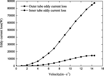
The eddy current loss of the secondary generated by a single permanent magnet.
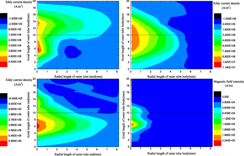
The spatiotemporal distribution of the outer tube eddy current and its magnetization at speed of 3 m/s.
The outer tube undergoes three different stages of permeability increased, permeability reduced, and magnetic saturation. The eddy current losses of low velocity 3 m/s and high velocity 14 m/s are compared and analysed, as demonstrated in Figs 12 and 13. The center line of the iron pole is located at an ordinate of 10 mm. It can be seen that the demagnetization effect of eddy current is weak at this time. The eddy current density in the departure end of the tube head, body and tail is not significantly greater than it in the approach end.
Due to the reaction of the secondary eddy current, the axial magnetization field is distorted. The magnetization of the outer tube is not uniform, accompanied by magnetic saturation in the departure end of the tube body.
The magnetization of the tube head and tail is different from that of the tube body. The reason for this phenomenon is that the maximum strength of the magnetic field is not located in the outer tube facing the iron pole. Since part of the fluxes directly enter the secondary, the axial fluxes are most evenly distributed and largest in the outer tube corresponding to permanent magnet. Therefore, the magnetization enhancement in the approach end at the low velocity of 3 m/s is not due to the eddy current field, as shown in Fig. 14. When the EMB is at the high velocity of 14 m/s, the magnetization enhancement away in the departure end from the end becomes obvious. The eddy currents in the tube head, the tube body and tail are gradually approaching the departure end. The magnetic saturation region is continuously expanding, which is in accordance with the theoretical analysis results.
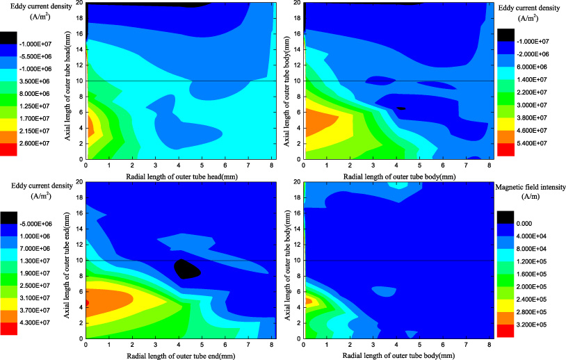
The spatiotemporal distribution of the outer tube eddy current and its magnetization at speed of 14 m/s.
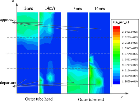
The magnetization field of the tube head and tail.
The eddy current loss in the permanent magnet and the iron pole is caused by the induced electromotive force of the secondary eddy current. The primary and the secondary eddy current are coupled to each other, and the directions are opposite. As exhibited in Fig. 15, primary eddy currents are concentrated during intensive impact loads. Then, the permanent magnet eddy current decreases rapidly without periodicity.
Integrating the eddy current density of a single permanent magnet and an iron pole, the eddy current loss is obtained as exhibited in Fig. 16. It can be found that the eddy current loss strengthens first and then weakens with the velocity, and the peaks of the eddy currents of the iron pole and the permanent magnet appear at 6 m/s and 11 m/s, respectively. The iron pole also exhibits magnetic saturation resulting in local permeability consistent with the free space.
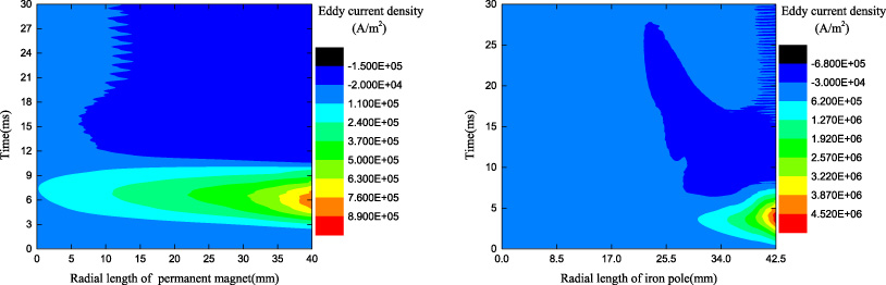
The spatiotemporal distribution of eddy current of (a) permanent magnet and (b) iron pole.
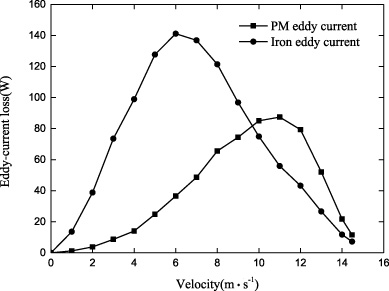
The eddy current loss of a single permanent magnet and iron pole.
In order to obtain the displacement, velocity and damping force characteristics under low, medium and high velocities, the experiment applied three different impact loads consistent with the FEM to the EMB as exhibited in Fig. 5. The test was carried out on the medium-hard soil with an ambient temperature of 10 °C to 15 °C. Then, the obtained test data is compared with the established FEM.
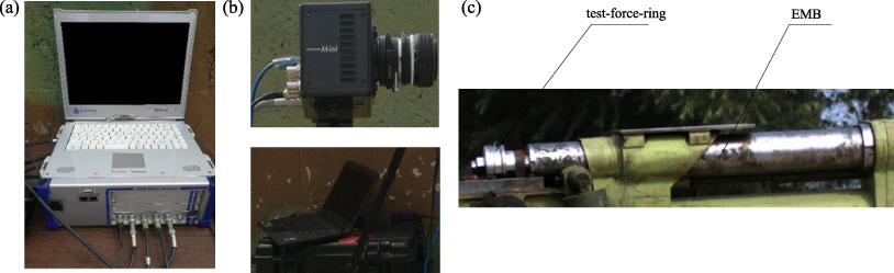
Experimental set-up for the prototype EMB. (a) Data acquisition device. (b) High-velocity photographic acquisition and storage equipment. (c) Fabricated prototype for proof of concept.
Figure 17(a) depicts the data acquisition device for the dynamic test platform of impact buffering. The force data is obtained by measuring test-force-ring attached to the end of the moving rod. The output terminal of test-force-ring is connected to a charge amplifier. Then, the inertial force is removed from force data measured by the test-force-ring to obtain reliable eddy current damping force. The laser displacement sensor is placed on the ground to test the displacement of the EMB. The acceleration sensor is mounted on the moving part connected to the primary. The damping force, acceleration and displacement obtained by the test are collected by the data acquisition device. At the same time, as given in Fig. 17(b), the displacement and velocity is also collected through high-velocity photographic acquisition and storage equipment. Then, the stored data are analysed by ProAnalyst software. As demonstrated in Fig. 17(c), a manufactured prototype EMB has been tested under the three different intensive impact load.
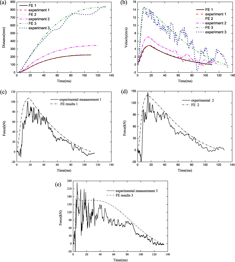
Comparison of experimental (a) distance–time, (b) velocity–time, (c) force 1-time, (d) force 2-time, (e) force 3-time characteristics with that calculated by simulation.
Figure 18 reflects the comparison of experimental results in terms of motion displacement, velocity and damping force with FEM simulation. As observed in Figs 18(a) and 18(b), the buffer displacement and velocity obtained by the FEM are in good agreement with those collected by the impact test in the case where the impact load 1 and 2 are applied. Although the test displacement has fluctuated, the test buffering completion time is consistent with the simulation results under the impact load 3.
Comparison of numerical simulation and impact test
Similarly, the test damping force curve obtained by the FEM is consistent with the experimental one in the case where the impact load 1 and 2 are applied. There is error between FEM result and experimental value. The reasons for the error are as follows:
(1) There are errors in the manufacturing and installation of EMB, especially for the processing of long composite tube. With the increase of machining length, the error of cutting tool will be enlarged. This error can lead to the change of damping process in impact test.
(2) The calculation of impact load is obtained by classical interior ballistics program, which is in accordance with the experimental impact load. However, it is assumed that 30% of the propellant has been burned at 0ms, therefore, there are some errors in the FE analysis.
(3) Piezoelectric force sensor itself will produce measurement error, and unreasonable installation stiffness will also cause error increase.
(4) The vibration of the sensor and signal line will cause the test displacement to fluctuate slightly.
It can be seen that the error between FEM result and experimental value of maximum velocity, maximum displacement and buffering completion time is very small. The absolute error of the velocity peak time and the damping force peak time is large, because the experimental value as the denominator is very small, as observed in Table 1.
The velocity peak time obtained under the impact load 1 and 2 is basically synchronized with damping force peak time, regardless of the experimental results or FE data. At this time, despite the demagnetization effect, the EMB still does not reach the critical velocity. The simulated damping force peak appeared at 7.1 ms, and the velocity peak appeared at 9.8 ms under the impact load 3 which is basically consistent with the experimental data. Therefore, the EMB exceeds the critical velocity due to the excessive demagnetization effect. It can be seen that the primary-secondary eddy current loss coupled nonlinear time-step FEM is adapted to the impact load buffering process with different impulse magnitudes, and the spatiotemporal distribution of the eddy current and its magnetization are reasonable.
In this paper, a primary-secondary eddy current loss coupled nonlinear time-step FEM for the proposed high-energy density cylindrical EMB is established. The non-uniformity characteristics of the spatiotemporal distribution of eddy currents and its magnetization effects are studied under intensive impact loads. The following conclusions are obtained:
(1) The secondary eddy current loss is positively correlated with the velocity, and its rate of increase is gradually softened due to demagnetization. The non-negligible eddy current is induced at the primary by the secondary eddy current field.
(2) The eddy current density in the departure end of the outer tube head, body and tail exhibits an increasing trend, at the same time, it shows a weakening trend in the approach end where magnetic saturation is occurring, especially at high velocity.
(3) The established primary-secondary eddy current loss coupled nonlinear time-step FEM is adapted to the impact load buffering process with different impulse magnitudes.
However, this model does not consider the impact demagnetization characteristics of the permanent magnet itself. Moreover, some of the test data generated fluctuations and test errors under intensive impact loads. Subsequent research is mainly to establish a complete FEM and test system to obtain the more reasonable spatiotemporal distribution of eddy current loss and its magnetization.
Footnotes
Acknowledgement
The work was primarily supported by the National Natural Science Foundation of China (grant number 301070603).