
Abstract
A fully implantable axial left ventricular assist device LAP31 was developed for Chinese or other heart failure patients who need partial support. Based on the 5-Lpm total cardiac blood output of Chinese without heart failure disease, the design point of LAP31 was set to a flow rate of 3 Lpm with 100-mmHg pressure head. To achieve the required pressure head and good hemolytic performance, a structure that includes a spindly rotor hub and a diffuser with splitter and cantilevered main blades was developed. Computational fluid dynamics (CFD) was used to analyze the hydraulic and hemodynamic performance of LAP31. Then in vitro hydraulics experiments were conducted. The numerical simulation results show that LAP31 could generate a 1 to 8 Lpm flow rate with a 60.9 to 182.7 mmHg pressure head when the pump was rotating between 9,000 and 12,000 rpm. The average scalar shear stress of the blood pump was 21.7 Pa, and the average exposure time was 71.0 milliseconds. The mean hemolysis index of LAP31 obtained using Heuser's hemolysis model and Giersiepen's model was 0.220% and 3.89 × 10⁵% respectively. After adding the splitter blades, the flow separation at the suction surface of the diffuser was reduced. The cantilever structure reduced the tangential velocity from 6.1 to 4.7–1.4 m/s within the blade gap by changing the blade gap from shroud to hub. Subsequently, the blood damage caused by shear stress was reduced. In conclusion, the hydraulic and hemolytic characteristics of the LAP31 are acceptable for partial support.
Keywords
Introduction
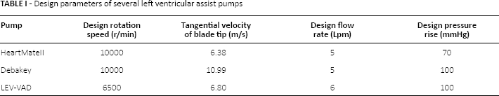
Since the rotary blood pump was used to treat heart failure patients in 1977 (1, 2), many research centers in the West have developed various successful products such as the Micromed DeBakey VAD, Jarvik 2000, HeartMate II, LEV-VAD, and Heart-ware (3-8). The design parameters of several well-known axial left ventricular assist blood pumps are listed in Table I. Traditionally, the design parameters of a blood pump are crucial to obtaining excellent hydraulic and hemolytic performance because the numerical results at the design point are the key to evaluate and improve its hemolytic performance. The list in Table I shows that the designed flow rates of all axial blood pumps are approximately 5 Lpm to satisfy the blood circulation requirements of heart failure patients in Europe and America (9). Although the total cardiac output of Chinese is approximately 5 Lpm and the blood pump generally provides less than 3 Lpm blood in animal experiment or clinical use (10-12), the flow rate at the design point was still set to 4 or 5 Lpm (13-15) when a blood pump is developed by Chinese researchers. Therefore, the left ventricular assist blood pumps developed by Chinese researchers could not function well at the optimal operating condition (16) when these blood pumps are used for Chinese heart failure patients.
- Design parameters of several left ventricular assist pumps
Over the past 10 years, an axial left ventricular assist blood pump LAP23, in which the design point is a 5-Lpm flow rate with a 100-mmHg pressure head, has been developed by our study group (17, 18). However, the common flow rate for partial support is 3 L/min and shear stress in the rotor blade tip clearance flow (the flow from the blade pressure surface to the suction surface across the rotor blade tip) inevitably causes serious hemolysis in the LAP23. Such hemolysis in the blade tip region can be reduced if the diameter of the blade tip is smaller. Studies showed that the rotor blade tip clearance flow in the radial clearance is one of the main causes of hemolysis (19, 20). To decrease the risk of hemolysis caused by the blade tip clearance, a novel axial flow blood pump LAP31 was developed.
Figure 1 shows the LAP31 blood pump. A brushless DC slotless motor drives the rotor impeller inside the pump. A spindly rotor hub was adopted to ensure satisfactory wash-out of the bearing area between the front and rear sides of the rotor impeller. To eliminate the hemolysis caused by higher shear stress in the rotational blade tip clearance flow, the hub of the rotor was designed as streamlined, and the cantilevered main and splitter blades of the diffuser were extended to the rotor hub of the LAP31. The pressure rise and flow rate at different rotational speeds were calculated by CFD and verified by in vitro hydraulics tests to improve the hydraulics property of the LAP31. A numerical simulation method was used to calculate the flow distribution, shear stress, exposure time, and hemolysis index of the pump.
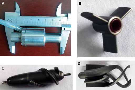
(A) Outline of LAP31; (B) Inlet guide vane; (C) Rotor; (D) Diffuser.
Materials and Methods
Design concept
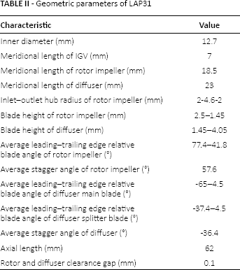
The structure of the LAP31, shown in Figure 2A, mainly includes 5 parts: a hollow stator cup, an inlet guide vane (IGV) with 3 blades, a rotor impeller with 2 blades, a diffuser with 3 main and 3 splitter blades, and magnetic steel. The diameter of the rotor blade tip was 12.7 mm, which is smaller than that of the LAP23 (16-18). The radius of the rotor impeller hub gradually increased from the leading to the trailing end following a cubic spline curve. The blade angle and blade thickness from the leading to the trailing end were obtained by curve fitting using a cubic spline curve. Bearings made of alundum (Al2O3) were installed between the IGV and rotor impeller and between the rotor impeller and diffuser to brace the rotating rotor. The 3 cantilevered main blades and the splitter blades of the diffuser extended into the rotor hub to arrange the outflow and change the clearance flow from the blade tip to the blade root. A lower hub ratio was adopted to reduce the diameters of the rotor impeller hub and decrease the risk of thrombus generation in the interfaces before and after the rotor impeller. The rotor blade tip clearance and diffuser blade root clearance were set to 0.1 mm for all blade designs. The main geometric parameters of the impeller and diffuser are listed in Table II.
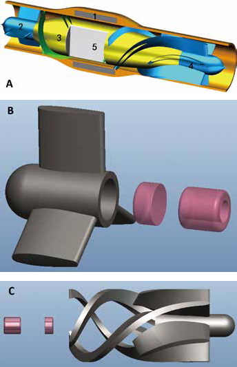
(A) Structures of the LAP31: 1. hollow stator cup, 2. IGV, 3. rotor impellers, 4. diffuser, 5. magnetic steel; (B) rotor and bearing; (C) diffuser and bearing.
- Geometric parameters of LAP31
A blade camber angle deflection of approximately 60° would appear when the diffuser changes from high-speed, spiral blood flow to smooth and steady flow along the axial direction. This deflection would cause vortex and backflow in the middle and posterior zones of the diffuser. The vortex and backflow would induce higher flow losses, longer blood exposure time, and more serious hemolysis. Accordingly, the first two-thirds of the 3 main blades of the diffuser were extended into the rotor, and three splitter blades were added to control the flow separation in the flow passage of the diffuser by increasing the local consistency.
Numerical simulation
A commercial CFD package solver (CFX 12.1; ANSYS) of the Reynolds-averaged Navier–Stokes equations was used to simulate the flow in the LAP31. A grid convergence study was performed to evaluate the influence of the number of grid elements on the accuracy of the CFD results and the computational convergence times. A meshed model was refined from 532480 to 900275 to get a finer mesh resolution in order to enhance the calculation accuracy of flow rate in the outlet region. The convergence criterion (residual of velocity, turbulent kinetic energy k, and dissipation energy e) was 0.00001, and the maximum iterations per time step were set as 50. Finally, the whole blood pump mesh had 900275 nodes without negative cells. The node numbers of the IGV, rotor impeller, and diffuser were 84165, 348105, and 468005, respectively. The whole mesh of only 1 blade passage that takes advantage of periodicity was used for calculation. The outlet region far from the diffuser blades was extended to improve the computational convergence stability and mesh quality. The O grids generated at the zones near the blades and the more refined grids near walls were specified to obtain the boundary layer properties. The convergence cutoff was 1 × 10⁶, and the average processing time for a steady flow computation condition took 5 hours on a double Intel Xeon 2.60 GHz processor. The boundary condition between the IGV and rotor impeller and that between the rotor impeller and diffuser were defined as rotational interfaces in the CFD simulation. The flow was defined as an axial flow at the inlet, the static pressure of 10 mmHg and temperature were provided here. In the outlet region, flow rates of 1, 2, 3, 4, 5, 6, 7 and 8 L/min were provided. The rotational speeds of the rotor impeller in LAP31 were specified as 9,000, 10,000, 11,000, and 12,000 rpm.
Although blood is normally considered as a non-Newtonian fluid, the blood behavior can be treated as Newtonian in most regions in LAP31 where the shear rate is above 100 s−1 (the shear stress is proportional to the velocity gradient with almost constant viscosity coefficient) (21, 22). The incompressible blood fluid parameters are listed as follows: density ρ of 1,055 kg/m3, and dynamic viscosity of 3.5 × 10⁻³ Pa·s.
The Reynolds number is defined as
where characteristic velocity U (m/s) is the tangential speed at the rotor blade tip, the characteristic length L (m) is the rotor blade tip diameter, and μ (m2/s) is the kinematic viscosity. The Reynolds number was then calculated to be approximately 1 × 10⁴, which means that turbulent flow dominated the whole flow status. In this study, the k (turbulent kinetic energy)–ε (viscous dissipation rate) turbulence model was used to solve the additional Reynolds stress terms by using the time-averaging procedure of the Navier–Stokes equations. This turbulence model has widely been used in the simulations of ventricular assist pumps. Meanwhile, it suffers from limitations such as inferior accuracy for low Reynolds numbers and in capturing the fluid characteristics during flow separation along the boundaries (1). Because of the low Reynolds number characteristic of the LAP31 flow (Re ≍ 1 × 10⁴), a logarithmic wall function was adopted to characterize and resolve near-wall flow conditions.
The stress damage and residence time in the blood determine the hemolytic property of the ventricular assist pump. Heuser's model (23, 24) has been widely used for the computational preliminary estimation of hemolysis in a blood pump and has been adopted in many other studies. The hemolysis estimation model is expressed by the following equation:

where Hb is the total hemoglobin concentration, ΔHb is the released hemoglobin concentration, t (s) is the exposure time, and τ (Pa) is the scalar shear stress (SSS).
In 1995, Bludszuweit proposed a computational method for a 1-dimensional SSS. He integrated the 6 tensors of stress to 1 stress with all the characteristics of these tensors, and it could be conveniently calculated (25). The 1-dimensional SSS (Pa) is defined by the following equation:
The calculation should consider both viscous and Reynolds stresses (24). The final SSS is the sum of these 2 types of stresses.
Hemolysis is related to both SSS and exposure time. In this study, Apel's method was selected to calculate the exposure time (26). The exposure time is defined by the following equations:
The final hemolysis index obtained using Heuser's model is defined by the following equation:
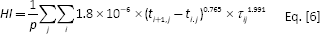
where P is the number of path lines, τi,j is the shear stress at step i of stream line j, and (ti+1,j - ti,j) is the exposure time of the stress x… The computational method of hemolysis proposed above would certainly be influenced by the selections of the path lines and time steps.
Another hemolysis estimated model defined by Giersiepen (27) was shown as the following equation model:

where Hb is the total hemoglobin concentration, ΔHb is the released hemoglobin concentration, t (s) is the exposure time, and τ (Pa) is the scalar shear stress.
In vitro test
We designed an in vitro experiment loop to test the hydraulics characteristics of the LAP31 (Fig. 3). The loop consisted of a fluid reservoir connected to the inlet and outlet of the LAP31 with silicon tube. The pressure of the outlet was made variable by clamping the outflow pipeline. Pump flow was measured with a flow sensor (type Turbotron VTH15). Pressure sensors (Setra 209) were placed at the inlet and outlet of the LAP31 to measure pressure head. The experiments were performed at a rotational speed of 9,000 ± 50 rpm, 10,000 ± 50 rpm, 11,000 ± 50 rpm, and 12,000 ± 50 rpm
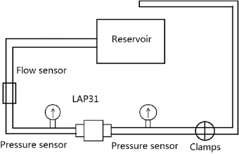
In vitro experiment loop.
Results
Hydraulic property and flow field
The numerical simulation was a steady-state simulation, and the static pressure at the outlet changed at each rotational speed and flow rate. Figure 4 shows the pressure rise with the flow rate characteristic of the LAP31 at rotating speeds of 9,000, 10,000, 11,000 and 12,000 rpm. The pressure rise reached 60.9 to 182.7 mmHg between flow rates of 1 and 5 Lpm. The working range covered the circulation requirements of Chinese heart failure patients.
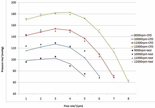
Pressure rise-flow rate characteristic of the LAP31 at different rotating speeds.
The design point of LAP31 was set to a 3-Lpm flow rate with a 100-mmHg pressure rise at 9,000 rpm. Figure 5 shows that the hydraulic efficiency ranges from 23.9% to 42.5%. At the design point, the hydraulic efficiency reached 38.9%, which corresponded with the typical performance of a blood pump.
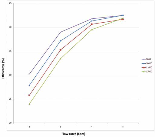
Hydraulic efficiency-flow rate characteristic of the LAP31 at different rotating speeds.
The flow pattern in the inducer was smooth, as shown in Figure 6A, and the IGV blades guided the flow to the inlet of the impeller. Figure 6B shows that the blood fluid flowed smoothly along the blades without flow separation in the impeller. The streamlines around the tandem cascade diffuser main and splitter blades are shown in Figure 6C. No backflow or vortex flow patterns were observed in the diffuser, but some flow vortex existed around the rearward blades owing to the increasing flow area.
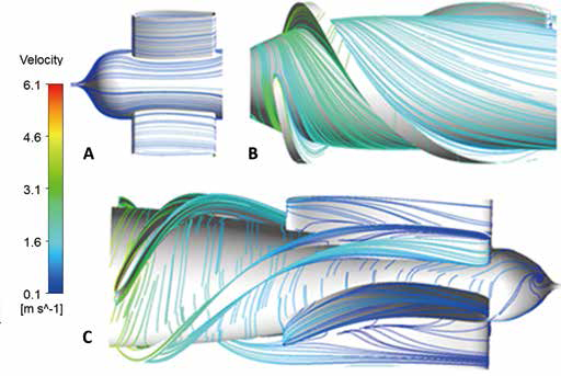
Streamlines at the hub and blades surfaces of LAP31: (A) IGV region; (B) impeller region; (C) diffuser region.
Figure 7 shows the three-dimensional (3D) streamlines at the design point of the LAP31. The blood fluid flowed smoothly along the whole passage without flow separation or backflow. A spiral flow occurred at the outlet of the LAP31. The tangential velocity at the blades tip clearance was 6.1 m/s.
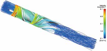
Distributions of the 3D streamlines.
Hemolytic property
Paul et al (28) proposed a blood damage standard as follows: if the SSS is under 425 Pa and the exposure time is below 620 milliseconds, the blood damage is small. Throckmorton et al (29) reported the blood damage threshold is approximately 500 Pa for an exposure time of 100 milliseconds. Figure 8A shows the SSS of the LAP31 at the design point. Most SSSs were less than 21.7 Pa, and high SSS occurred at the leading edges of the rotor blades. At the design point, the peak SSS occurring around the leading edges of the impeller blade tips is under 386.6 Pa.
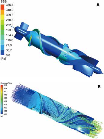
Distributions of the SSS, the streamlines, and the exposure time. (A) SSS at the design point. (B) Exposure time and streamlines at the design point.
This study adopted different numbers of particles, namely, 292, 450, and 600 to calculate the exposure time. All the fluid particles were considered to start at the pump inlet at an initial time equal to zero and terminated when they left the pump outlet. The residence times of the blood particles in the whole pump region were less than 156.3 milliseconds (Fig. 8B)
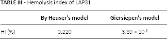
This study adopted #292, #450, and #600 particles to calculate the hemolysis index. After adopting 600 streamlines and 50 smaller time steps, the hemolysis index of the whole blood pump at the design point was estimated to be 0.220% and 3.89 × 10⁻⁵% by the 2 models respectively (Tab. III). The selections of the path lines and time steps actually exerted some effects on the estimated hemolysis index. However, the result, which adopted sufficient path lines and sufficiently small time steps, was acceptable as a computational method with a small difference.
- Hemolysis index of LAP31
Discussion
The design point of the LAP31 was chosen at 3 Lpm and 100 mmHg with a 9,000-rpm rotational speed. The hydraulic efficiency reached 38.9% at the design point within a normal efficiency range of blood pumps. The cantilevered blades of the previously proposed diffuser were further developed in terms of the structure design of the LAP31, combined with the splitter blades. The cantilevered blades of the diffuser have been proposed in the blood pump field (6, 9) and were used in the design. At a flow rate of 3 Lpm, the blood pump in our previous study generated a pressure rise of nearly 100 mm Hg at 8,000 rpm with an impeller diameter of 17.5 mm (17). Meanwhile, the LAP31 produced a pressure rise of approximately 100 mmHg at 9,000 rpm with an impeller diameter of 12.7 mm while the radius of rotor hub increased from 2.0 to 4.6 mm then decreased from 4.6 to 2.0 mm with a streamlined curve. The tangential speed of the impeller blade tip decreased from 7.3 to 6.1 m/s, and even the tangential speed of the diffuser blade tip decreased to 4.7–1.4 m/s by adopting such a streamlined hub with the cantilevered main and splitter blades of the diffuser extended to the rotor hub; thus, the shear stress also decreased.
In the LAP31, the pressure rise across the impeller was evident. By adopting the splitter blades, smooth flow patterns dominated the flow fields in the LAP31 diffuser without separate and stagnant flows. The blood pump that adopted such diffuser structures increased the blood pressure from 97.7 mmHg to 132.1 mmHg.
The hemolytic property is the major concern in designing a rotary blood pump. Paul et al reported a damage threshold level of 425 Pa for exposure times of 620 milliseconds in a Couette device, which is conceptually similar to an axial flow blood pump (28). In the LAP31, the calculated SSSs were less than 21.7 Pa in most regions while the peak SSS 386.6 Pa occurred around the leading edges of the impeller blade tips. The maximum time for the blood to pass through the whole pump was less than 156.3 milliseconds. The LAP31 reached the same level of SSS and residual time as LEV-VAD (7). Throckmorton et al reported that the mean value of the blood damage index was approximately 0.09% in their axial flow blood pump (23), and the estimated formula of damage to red blood cells that they used was Heuser's model (Eq. [6]). The turbulence and SSS models that they adopted were the same as those used by us. Taskin et al (30) reported that the highest and lowest HI were found to be 4.67d10−0 and 8.09 10−0 in their axial flow blood pump. The hemolysis index is 3.75 × 10⁻⁵ for the HVAD and 3.85 × 10⁻⁵ for the Heartmate II (31). By comparing the damage index with our result, the averaged hemolysis index of the LAP31 obtained using Heuser's model was 0.220%, the averaged hemolysis index of the LAP31 obtained using Giersiepen's model was 3.89 × 10⁻⁵%. The hemolysis index of the LAP31 is acceptable according to the research of Throckmorton et al (23), Taskin et al (30) and Thamsen et al (31).
The simulations and experiments were performed using a steady flow, although the flow rate through continuous pumps varies as a result of the native heart beat. This simplification is common practice in blood pump design. The range of working conditions chosen for this study has covered the conditions that a partial-assist blood pump will experience during clinical use with a native heart. The mean flow field and turbulent stresses for steady and pulsed flow have been compared to a centrifugal blood pump (32). It was shown that the details of the flow field between the pulsed flow case and steady flow case at the corresponding flow rate are similar. So the range of steady flow steady assumption is representative of working conditions that the blood pump will experience in clinical use.
To date, the work still suffers from some limitations. Irregular flow status in the diffuser region and spiral flow still exists at the outlet of the pump. The low wall shear stresses, recirculation and wash-out close to the bearing region was not been estimated because the bearings structure was simplified in the simulation. Further flow pattern optimization should be done in the future.
Conclusions
The novel structure of cantilevered main and splitter blades of a diffuser has been successfully used in a partial-assist blood pump for Chinese and other heart failure patients. Hemolysis in the LAP31 blood pump was improved because the tangential velocity of the blades tip was reduced. The design point of a 3-L/min flow rate with a 100-mmHg pressure rise satisfies the clinical requirements of partial-assist. This research changes the neglected status of the current circulation assist demands of Chinese heart failure patients.
In general, this LAP31 study serves as a starting point for the future design of left ventricular assist blood pumps for partial-assist. More design and experimental studies will be carried out to obtain further understanding in developing blood pumps with better performance.
Footnotes
Conflict of interest: None of the authors has financial interest related to this study to disclose.