
Abstract
Severe plastic deformation (SPD) is known to be the best method for producing bulk ultrafine-grained and nanostructured materials with excellent properties. Different SPD methods were developed that are suitable for sheet and bulk solid materials. During the past decade, efforts have been made to create effective SPD processes suitable for producing cylindrical tubes. In this paper, we review SPD processes intended to produce ultrafine-grained and nanostructured tubes, and their effects on material properties. The paper will focus on introduction of the tube SPD processes, and then comparison of them based on their advantages and disadvantages from the viewpoints of processing and properties.
Keywords
Introduction
It is well known that the room temperature mechanical properties and high-temperature superplastic behaviour of polycrystalline metals depend on microstructural characteristics and especially, on the grain size. 1 A decrease in the grain size leads to enhanced strength of the metal at room temperature, according to the well-known Hall–Petch relationship. 2 A reduction in the grain size also provides superplastic forming capability at elevated temperatures. The grain size is one of the most important characteristics of a polycrystalline metal microstructure. The common grain size of the metals in industry is >10 µm and are called coarse-grained materials. Fine-grained metals that are processed using industrial thermomechanical processing have grain size of ∼1–10 µm. 3 It is hard to achieve a metal with grain size <1 µm (called ultrafine grained) or <100 nm (called nanograined) when using conventional thermomechanical and conventional metal-forming processes.1,2,4 The main reasons may be the limited amount of plastic strain that results from limitations in the reduced cross-section, limited values of hydrostatic compressive stresses and the lack of high-angle grain boundaries.5,6
Severe plastic deformation (SPD) methods are advanced metal-forming processes that apply high levels of hydrostatic stress without changing the material cross-section and are capable of producing ultrafine-grained metals with high-angle grain boundaries. 7 Bridgman 8 presented a new horizon for material processing using a combination of high hydrostatic pressure and shear deformation, which today is at the core of the SPD methods. A large number of SPD processes have been proposed during the last 20 years for producing ultrafine-grained and nanograined metals. The differences between them are mainly relevant to the deformation behaviour, the shape of the workpiece, the strain imposed per pass and the processing load required. From the workpiece shape point of view, SPD methods may be classified as suitable for bulk, for sheet, or for tubular components. 9 Equal-channel angular pressing (ECAP),2,10 cyclic extrusion-compression 11 and high-pressure torsion 12 are the oldest and main SPD processes suitable for bulk metals. There are many addition methods for dealing with bulk materials (twist extrusion,13,14 torsional-ECAP, 15 multi-axial forging, 16 cyclic expansion-extrusion, 17 cyclic close-die forging, 18 repetitive forging using inclined punch, 19 repetitive upsetting 20 or repetitive extrusion and upsetting, 21 accumulative back extrusion,22–24 expansion ECAP, 25 constrained groove pressing, 26 equal-channel forward extrusion, 27 parallel-ECAP, 28 pure shear extrusion, 29 vortex extrusion, 30 friction stir processing,31,32 elliptical cross-section spiral equal-channel extrusion,33,34 hydrostatic ECAP, half channel angular extrusion, 35 C-shape equal-channel reciprocating extrusion, 36 accumulative press bonding 37 and the tandem process of simple shear extrusion and twist extrusion 38 ).
The SPD processes listed above are suitable for processing of ultrafine-grained and nanograined metals at laboratory scales. Scaling up these SPD methods remains a challenge for the scientific community. During the last decade, industrial demand for large, high-strength ultrafine-grained samples has pushed researchers to develop methods suitable for processing large samples using continuous processes like incremental high-pressure torsion, 39 continuous high-pressure torsion, 40 ECAP-Conform, 41 incremental ECAP and equal-channel angular drawing. 42 There are other processes that are appropriate for sheet form samples and are almost continuous processes. These include accumulative roll bonding, 43 equal-channel angular rolling44,45 or continuous confined strip shearing, 46 accumulative roll bonding and folding, 47 repetitive corrugating and straightening, 48 cone shearing and continuous frictional angular extrusion. 49
Some other methods are combinations of conventional metal-forming and SPD methods suitable for possible industrial applications. These include, ECAP followed by rolling, 50 ECAP followed by extrusion, 51 integrated extrusion-ECAP, 52 ECAP-conform and drawing, 53 hydrostatic extrusion (HE), 54 asymmetric rolling,55,56 torsion extrusion, 57 cryogenic rolling, 58 severe torsion straining, 59 HE combined with torsion, 60 twist extrusion and subsequent rolling, 61 a method without SPD, 62 integrating forward extrusion and torsion deformation, 63 calibre rolling 64 and SPD using the KoBo process.65,66
Several reviews could be found in the literature about SPD processes and ultrafine-grained materials,1,4,7,12,67–71 but almost no review paper could be found about SPD methods suitable for tubular hollow components. The current review provides insightful knowledge about the tube SPD processes, comparison of their use in manufacturing and properties, advantages and disadvantages, and future horizons. During the last decades, a number of SPD processes have been proposed. These include ECAP for hollow parts, 72 tubular channel angular pressing (TCAP), 9 parallel tubular channel angular channel (PTCAP), 73 combined PTCAP, 74 tube channel pressing, 75 cyclic flaring and sinking, 76 other combined processes,77,78 high-pressure tube twisting, 79 tube high-pressure shearing, 80 accumulative spin bonding, 81 tube cyclic extrusion-compression 82 and tube cyclic expansion-extrusion. 83 There exist other methods that may not be classified as SPD processes because of a change in the cross-sectional area of the product. One necessary characteristic of an SPD process to distinguish it from conventional metal-forming processes is that the cross-section dimensions of the workpiece must remain unchanged. This allows repetitive pressing to create an accumulation of very large strains. There are still newly developed conventional metal-forming processes with the capability of processing large-scale samples while applying intense plastic deformation.
SPD processes suitable for tubular samples
ECAP for hollow parts
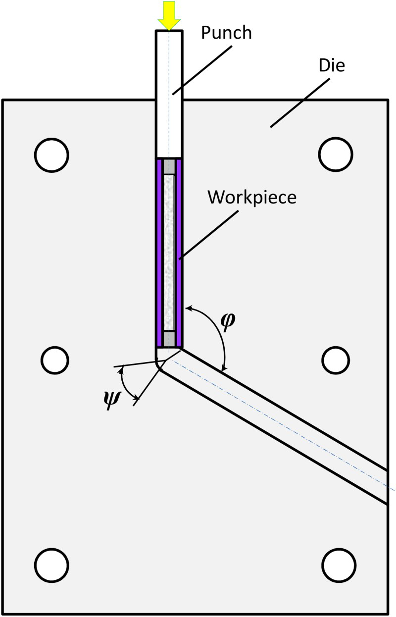
From the year 2006, researchers have used the ECAP process, which is normally suitable for solid materials, as a candidate for hollow tubular components as shown in Fig. 1. Therefore, a flexible mandrel has to be used inside the tube to prevent buckling during the process. Nagasekhar et al.
72
processed a Ti Grade 1 tube using sand as a flexible mandrel in an ECAP die, with 150° and 30° corner and curvature angles, respectively. It was shown that the process has little impact on the mechanical properties. The strength remained almost unchanged while the ductility was decreased. Under the same condition, Valder et al.
84
processed commercially pure Al using different equal-channel angular-pressing routes. A maximum plastic strain of ∼0.9 was imposed. It seems that higher level of strains could not be achieved under the condition of this process because of insufficient hydrostatic stress. Therefore, producing ultrafine-grained and nanostructured Al tubes with high-angle grain boundaries could not be obtained. Djavanroodi et al.
85
produced commercial pure copper ultrafine-grained tubes with the conventional 90° equal-channel angular-pressing die using polyurethane rubber as a mandrel. They also investigated the effect of the route in tube-ECAP process.
86
The results exhibited that the grain size was reduced about 25 µm after a four-pass equal-channel angular-pressing process. In comparison with the grain size of ∼0.4 µm for a solid sample after four passes of conventional ECAP, the ultrafine-grained structure may not be produced using tube-ECAP. Equal-channel angular-pressing processing of 6061 Al tube using a 120° equal-channel angular-pressing die, and hydraulic oil as mandrel, was done by Zalnezhad and co-workers.
87
Although simple conceptually, using oil may involve problems like sealing during the process. The compressibility of the fluid might also cause defects and heterogeneous distribution of thickness of the tubular material, as well as decreasing the hydrostatic stress on the material and consequently lowering its strength and ductility. All the references on tube ECAP reported strain inhomogeneity in the peripheral direction of the processed tube.85–87 Because the hardness distribution is influenced by the strain homogeneity,88,89 a heterogeneous distribution of hardness might occur.
Illustration of ECAP as a candidate for tube processing
87
Tubular channel angular pressing
The first effective method (TCAP) was based on ECAP without having the limitations of the tube ECAP process and was developed in 2001 by Faraji et al.
9
Segal showed that the performance of an equal-channel angular-pressing die might be compromised by a die design that appears simple, having sharp corners. In particular, he warned against the use of dies with a corner arc, which leads to the occurrence of a widely spread fan-shaped plastic zone.10,90 This is equivalent to artificially increased friction, which spreads shear and gives rise to significant heterogeneity of strain. Unfortunately, this important warning was disregarded in many later studies, which utilised a simplified die design with a rounded outer corner (such as Luis geometry for equal-channel angular-pressing die
91
). For this disregard, a high price was paid in the form of substantial heterogeneity of the deformed structure, along with a decrease in the hydrostatic compressive stresses and workability of the metal. In contrast, by following Segal's philosophy, samples with uniform microstructure throughout the billet could be fabricated.
68
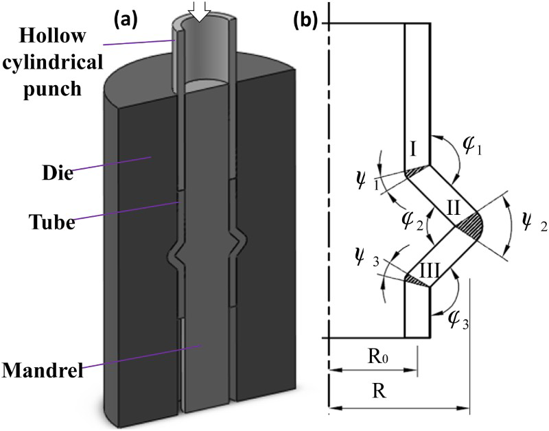
The TCAP process herein proposed is in accordance with this important recommendation of Segal. A schematic illustration of the TCAP is depicted as in Fig. 2. The tube constrained by the mandrel and outer die is pressed by a hollow cylindrical punch into a tubular angular channel, while three axisymmetric shear events take place during one processing pass. From the actions of the axisymmetric shear strains, strain homogeneity along the peripheral direction of the tube could be estimated. The TCAP process may be repeated to achieve large strains without any reduction in the cross-section. The die parameters shown in Fig. 2b affect the processing load and deformation behaviour analysed.
92
Investigations on the effect of friction conditions were studied in detail in Faraji et al.
93
The semi-circular geometry of the process in comparison with the triangular one was also presented and studied using the finite element method.
94
It was revealed that lower force, better strain homogeneity and lower hydrostatic stress were achieved within semi-circular geometry.
95
An increase in the die angles (φ1 and φ2) exhibited similar effects for a semi-circular channel.
92
The process load is one of the most important features of the process. Attempts were made to decrease the TCAP process force using application of ultrasonic vibration.
96
It was shown that by application of ultrasonic vibration to the hollow punch, the processing load was slightly decreased. However, application of ultrasonic vibration to the die exhibited a significant reduction of force. Especially, when applying force in the radial direction, the processing load could be decreased about 80%.
96
This is because that ultrasonic vibration significantly decreases the friction coefficient and the friction force is a large part of the TCAP load.
97
Until now the TCAP process has been successfully applied to AZ91,
9
AZ31
98
and commercially pure Al.
99
a A schematic of TCAP and b processing parameters
100
Parallel tubular channel angular channel
While it is able to apply high hydrostatic compressive stress to the material, which is crucial for achieving ultrafine-grained structure with high-angle grain boundaries,
68
the process of TCAP has some limitations. The inability of TCAP to process long tubing is one of its most important limitations. The total process load is the sum of deformation, redundant and frictional forces. Deformation and redundant forces remain constant when the tube length is changed. However, the friction force is changed dramatically when processing long tube, and consequently, the total force will increase. Because of the hollow geometry of the cylindrical punch with limited yield strength and buckling strengths, there is a limitation in the tube length. Also, when the tube length increases, the length of the hollow punch has to be increased, causing the buckling strength to decrease. The ultimate limit on the length of a tube processed in this way is dependent on a combination of factors that include the tube material, die geometry, thickness and diameter of the tube, process parameters and lubricant. For example, for AZ91 tubing and the process conditions of Faraji et al.,
9
the tube length must not exceed ∼40 mm, otherwise the punch will fail. Thus, the decrease of the processing load may be a significant challenge. To resolve this issue, the PTCAP process was presented by Faraji et al.
73
in 2012. The PTCAP process consists of two half cycles and is shown schematically in Fig. 3. At the start of the process, the initial tube is put into the gap between the mandrel and die, as shown in Fig. 3a. In the first half-cycle, the tube material is extruded by the first punch into an angular tubular channel having two axisymmetric shear zones, so that the tube diameter is increased (Fig. 3b). The tube material, in the second half-cycle, is then re-extruded into the shear zones by the second punch at the other end of the tube. The process may be repeated as many times as necessary to obtain a distinct strain, without any alteration of the cross-section of the workpiece. The effects of the die parameters as shown in Fig. 3d, on the processing load and deformation behaviour, were analysed in Faraji and Mousavi Mashhadia.
101
Schematic illustration of PTCAP process a initial state, b the first half-cycle, c the second half-cycle and d die parameters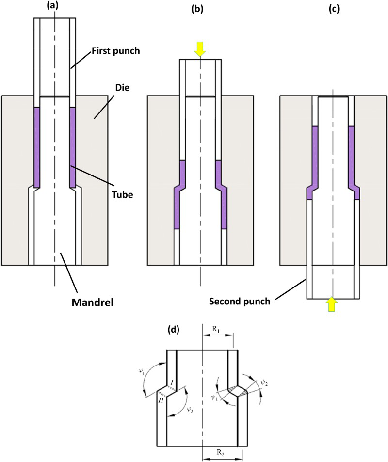
Compared to the TCAP process, ∼60% lower process load is applied in the PTCAP process. 73 This may be an important advantage of the PTCAP process, making possible processing of tubes longer than possible with the TCAP process. The PTCAP process was applied to pure copper, 102 Al 6061 103 and AZ31 magnesium alloy. 74 Albeit the PTCAP process may produce relatively longer ultrafine-grained tubes compared to TCAP, the problem of thin-wall tube processing remains unsolved. To overcome this limitation, several approaches have been tried and some of the following methods are the outcomes.
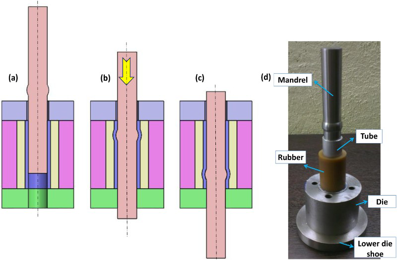
Combined PTCAP
Although the TCAP and PTCAP process could produce ultrafine-grained thick-walled tubes, these two processes could not be applied for thin-wall ones. When processing a thin-walled tube by PTCAP or TCAP, the length of the tube is dramatically decreased because the cross-section of the punch is identical to that of the tube. The friction force is changed dramatically for thin-walled tube processing while the deformation force remains unchanged. On the other hand, the reduced thickness of the punch drops its bearing force capacity. This then, presents a significant challenge when processing thin-walled tubes by TCAP or PTCAP. To solve this, Abdolvand et al.
74
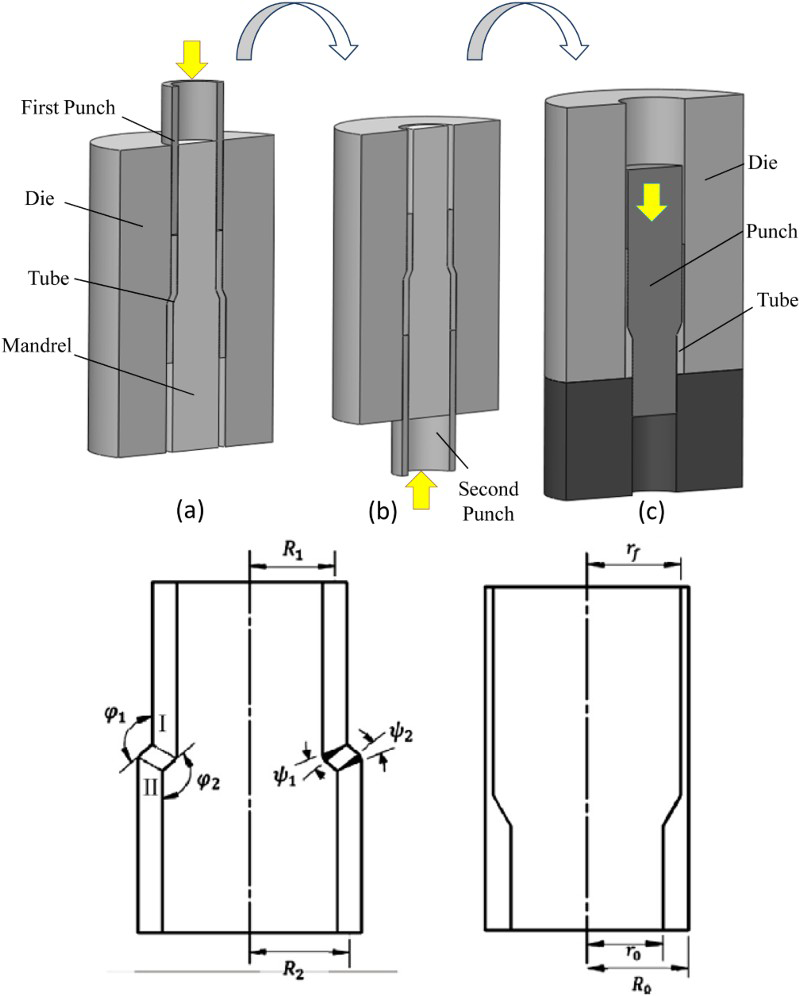
presented a combined method of two stages: one a PTCAP and the second a tube back-extrusion process. First, the PTCAP process is applied to produce an ultrafine-grained thick-walled tube, and then the tube back-extrusion process is consequently applied to lessen its thickness. The combined PTCAP process is shown schematically in Fig. 4.
74
As shown, the PTCAP-processed tube is consequently back-extruded via a die. An AZ31 magnesium alloy thin-walled ultrafine-grained tube with thickness of 0.75 mm was successfully processed with an extrusion ratio of ∼70%, resulting in a total applied plastic strain of about 2.8.
74
Schematic of the combined process: a First and b second half-cycles of PTCAP, and c tube back extrusion, d die parameters in both PTCAP and tube back extrusion stages
74
Tube channel pressing
Another SPD method called tube channel pressing, based on an ECAP process similar to Luis geometry,
91
was developed by Zangiabadi and Kazeminezhad.
75
In this method, a tube is pressed into a tubular channel having a neck zone as shown in Fig. 5. Utilisation of a mandrel fitted inside the tube prevents crumbling of the tube and preserves its first dimension. After the first pass, the die is rotated upside down, due to the symmetric design, and the second pass is done by pressing the tube in the reverse direction.
Schematic and procedure of tube channel pressing: a Beginning of the first pass, b end of the first pass and c beginning of the second pass
75
There exists two different ECAP die geometries (Segal
4
and Luis
91
), as shown in Fig. 6. The difference between the tube channel pressing and TCAP process may be considered the different channel geometry used in the processes. The TCAP method employed Segal geometry, while in the tube channel pressing method Luis geometry with larger corner radius (R) was used. The force in tube channel pressing may slightly less that of the TCAP process, but the total strain and also the type of strain are different. It is well known that shear strains have the main role in the grain-refinement process.
22
During the tube channel pressing process, less shear strain and more bending, tensile and compression strains are applied. However, in the TCAP process more shear and less tensile and compression strains are applied.92,94 This means that the TCAP process may produce more grain refinement at the same equivalent plastic strains.
Two different ECAP die geometries a Segal geometry and b Luis geometry
4
Cyclic flaring and sinking
The cyclic flaring and sinking process that was developed by Torabzadeh et al.
76
includes two different flaring and sinking half-cycles. For the flaring half-cycle, as shown in Fig. 7, the flaring punch is pressed into the tube. At this stage, normal and shear strains are applied because of an increase in the tube diameter and the existence of shear zones. The tube is then pressed onto a sinking die that applies shear and normal compression strains in the second half-cycle. Total strain in each pass of cyclic flaring and sinking is the sum of the strains applied in the two half cycles. In contrast with the advantage of the cyclic flaring and sinking in producing long thin-walled tubes, the lack of adequate hydrostatic stress may be considered its disadvantage.
Schematic of cyclic flaring and sinking a initial state, b flaring (first half-cycles), c sinking (second half-cycles) and d parameters
76
High-pressure tube twisting
The first SPD process based on high-pressure torsion (called high-pressure tube twisting) was developed by Toth et al. in 2009.
79
The experimental set-up of the high-pressure tube-twisting process presented
79
is shown schematically in Fig. 8. As shown, the tube sample is placed inside a rigid disk and a mandrel is located in the tube. The mandrel is elastically compressed with a compression machine to expand slightly in the radial direction. Because its expansion is constrained by the tube, the disk builds up a large hydrostatic stress in the tube and provides a large friction force on both sides of the tube. Finally, rotating the disk causes deformation of the tube. It was shown that a very large shear strain gradient was achieved along the tube thickness. Compared to previous SPD methods, high-pressure tube twisting is a semi-continuous process that has the capability of applying a large amount of strain without damaging the test sample. Arzaghi et al.
104
applied the high-pressure tube-twisting method to a commercially pure Al up to the shear strain of about 24, in a single stage. Very high hydrostatic pressure, applying only pure shear (almost no normal strains) and the capability of applying high strains in a single stage are important advantages of this process. Despite these advantages, high-pressure tube twisting does have limitations: complicated apparatus, it is hard to scale up for large samples and the strain is inhomogeneous.
105
This method was also used to produce bilayer tubes. Lapovok et al.
106
employed a modified high-pressure tube twisting for fabrication of aluminium–copper bimetallic tubing. A comparison between three SPD processes (high-pressure torsion, high-pressure tube twisting and cone–cone method)
107
that benefit from friction and high hydrostatic stress was outlined by Lapovok et al.
105
Schematic of the high-pressure tube-twisting set-up under high hydrostatic pressure
79
Tube high-pressure shearing
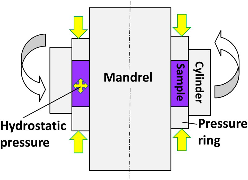
A modified high-pressure tube-twisting process called tube high-pressure shearing was presented by Wang et al.
80
The principle of tube high-pressure shearing is illustrated schematically in Fig. 9. The tube sample is radially constrained between a mandrel and an outer cylindrical die. The process applies a sufficiently high hydrostatic pressure to the tube so that the frictional forces at the interfaces between the sample and mandrel limit any localised slip. By rotating the outer cylinder while fixing the mandrel, a simple shear is produced in the tube material. To introduce hydrostatic stress to the tube sample, different procedures were used in high-pressure tube twisting and tube high-pressure shearing. In high-pressure torsion, a radial force is applied to the tube sample by compressing the mandrel within an elastic regime in which the mandrel is expanded; so that hydrostatic stress will build up. In tube high-pressure shearing, axial compression is applied directly by the pressure rings, making this process more practical than high-pressure tube twisting. The redesigned, modified version of high-pressure tube twisting used by Arzaghi et al.,
104
and illustrated in Fig. 10, seems to be the best design from a manufacturing point of view. This is because the set-up is similar to conventional high-pressure torsion and because there is no need for complicated apparatus.
Schematic of the tube high-pressure shearing process in which compression of the pressure rings introduces a hydrostatic stress to the tube sample
80
Schematic of the modified high-pressure tube-twisting set-up
104

Accumulative spin-bonding process
There is just one accumulative roll bonding-based SPD process for tubes called accumulative spin bonding, and it was developed in 2010. Accumulative spin bonding is an SPD process with all advantages and disadvantages of accumulative roll bonding with sheets. It was proposed by Mohebbi and Akbarzadeh
81
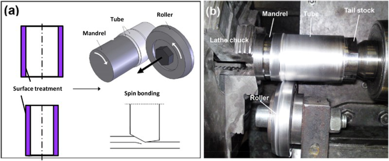
for fabrication of high-strength thin-walled tubes. Before accumulative spin bonding, the spin-bonding process as shown in Fig. 11 was presented by the same authors as a method for manufacturing multilayered, clad tubes.
108
Spin bonding is conventional tube spinning109,110 or flow forming
111
of the multilayered tube. This is a process in which the thick-walled workpiece rotates on a mandrel, while one or more rollers move axially along the sample axis to reduce its thickness. Flow forming may be classified as either forward or backward routes
112
where the backward one may be used for materials with less ductility. Backward flow forming can be used to apply more compressive stress, which plays the main role in the forming of brittle materials to avoid crack initiation and propagations.109,113,114
a Schematic of the spin bonding and b forward flow-forming set-up
108
In the accumulative spin-bonding process, the spin-bonding method was repeated up to several cycles (four cycles in Mohebbi and Akbarzadeh
81
). The surface treatment is a critical stage of processing to provide good bonding between layers.115,116 Surface-treated tubes are placed against each other and positioned on the mandrel for flow-forming at room temperature. Then, the tube and mandrel rotate while a roller moves along the tube axis to reduce its thickness up to 50% to create bonding between the tubes. In the common accumulative roll bonding process, the sheet is cut after bonding and two parts are stacked for the next pass.
117
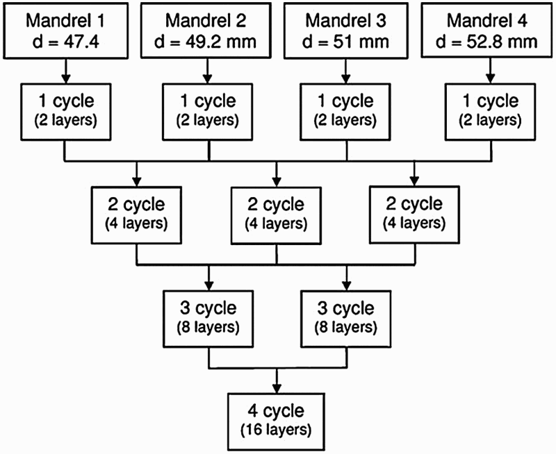
In the accumulative spin-bonding process, the plan shown in Fig. 12 is used. As shown, the number of required mandrels is equal to the number of accumulative spin-bonding cycles. So, four mandrels with different diameters were utilised to perform four cycles of accumulative spin bonding.
81
The spin-bonded tube on Mandrel 4 is used as the external tube for the second cycle of accumulative spin bonding on Mandrel 3. Then, the spin-bonded tube was bonded to another spin-bonded tube on Mandrel 2 for the third cycle of accumulative spin bonding. The fourth stage, in a similar procedure, was carried out on Mandrel ‘1’ by spin-bonding of two tubes processed by three cycles accumulative roll bonding. Finally, a 16-layered, cold-welded and strained accumulative spin-bonding-processed tube could be obtained after four cycles of this method. It seems that the accumulative spin-bonding process may produce relatively longer and larger tubes compared to other SPD techniques. This could be an important advantage of this method. However, the occurrence of defects between the layers may be considered a limitation of accumulative spin bonding.
99
ABS design (four cycles) using four mandrels with different diameters
81
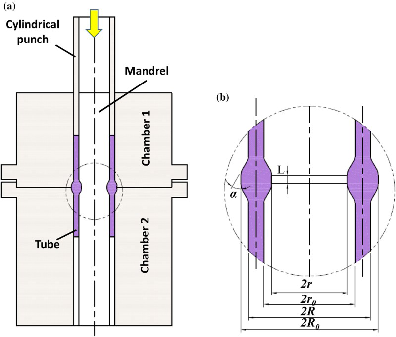
Tube cyclic extrusion-compression
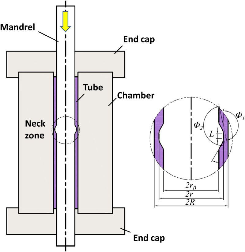
The process called tube cyclic extrusion-compression was presented by Babaei et al.
82
in 2014. The tube cyclic extrusion-compression die set-up is as shown in Fig. 13. The tube sample is placed among mandrels with an expanded zone at the middle and a cylindrical chamber that is constrained from top and bottom by two end caps. During the deformation, the tubular samples always have a constant volume and fully enclose the space among the mandrel, chamber and two end caps. The enclosed tube sample is strained by pressing the mandrel which has an expanded zone. The tube cross-section is first reduced while being extruded from the neck zone, and then is compressed to an initial thickness after passing the neck area. The tube thickness remains almost constant before and after the deformation zone. Though the tube cyclic-extrusion compression process may deform longer tubes compared to the TCAP,
118
tube channel pressing
75
and PTCAP
101
processes because it employs a solid mandrel, it is impossible to process very long tubes for two reasons. First, with an increase in the length of the tube, the friction force between the mandrel and the inner surface of the tube increases and consequently the total force increases. Considering the limited mandrel cross-section, it will fail by buckling or yielding. Second, compression and extrusion of the tube material in the necked zone takes place by hydrostatic stress provided from the end caps. The increase in the tube length causes less hydrostatic stress in the deformation zone as the results of friction force.
Illustration of the tube cyclic extrusion-compression process and parameters.
82
Tube cyclic expansion-extrusion
Similar to tube cyclic extrusion-compression, the tube cyclic expansion-extrusion process was developed by the same authors.
83
A schematic of the tube cyclic expansion-extrusion process die and parameters are as shown in Fig. 14.
83
In tube cyclic expansion-extrusion, an expanded zone of the tube sample is produced by two annular grooves on the mandrel and inner surface of the chamber. The tubular workpiece, constrained between the mandrel and chamber, is compressed between two cylindrical punches to expand it in the grooves at the start of the process. Then, the lower hollow punch is removed, and the sample is pressed by the upper hollow punch towards the expansion zone. This causes cyclic expansion and extrusion of the material. That no back pressure is needed is an important advantage of the tube cyclic expansion-extrusion process over tube cyclic extrusion-compression.
17
However, tube cyclic expansion-extrusion has an important limitation compared to its tube cyclic extrusion-compression counterpart. The length of a tube for processing by tube cyclic expansion-extrusion is limited by the buckling or yielding of the hollow punch. As mentioned earlier this limitation can be found in some other SPD processes for tubular products that make them unsuitable to scale up for industrial application.
a Schematic of tube cyclic expansion-extrusion process and b die parameters
83
Rubber pad tube straining
Very recently, rubber pad tube straining was developed by Shapoorgan and Faraji
119
for processing of relatively long and thin-walled tube. The process is similar to TCAP process with semi-circular die geometry, but takes advantageous of a rubber pad instead of a rigid die. This provides a rigid mandrel for pressing instead of hollow punch that makes the method suitable for processing relatively long and thin-walled nanostructured tubes. The schematic of rubber pad tube-straining process and the die set-up was as shown in Fig. 15. The mandrel is pressed down until the convex part reaches the edge of the tube as shown in Fig. 15a. The tube is locally deformed by the mandrel as shown in Fig. 15b and the diameter of the tube increases. When the mandrel is pressed down, the deformation zone incrementally moves along the tube length. During the deformation, the rubber pressure pushed back the tube on the mandrel to keep the tube diameter constant in the regions before and after the deformation zone. Finally, the mandrel reaches the end of the tube as shown in Fig. 15c.
Schematic of RPTS process a initial state b during the process and c end of the process, and d RPTS die set-up
119
Other combined processes
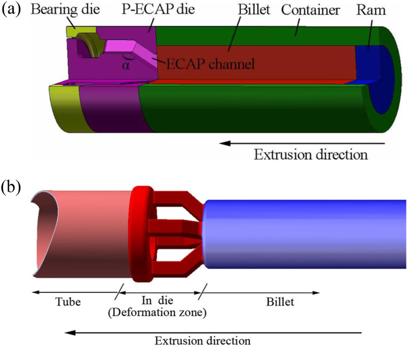
One of the most important challenges in the SPD process is a lack of effective industrial methods to scale them up to produce long and large workpieces.120,121 In recent years, several attempts have been made to combine conventional metal-forming processes with SPD techniques. Several combined SPD processes are presented here. A porthole-ECAP method combining conventional porthole extrusion122,123 with four-port ECAP was employed to produce a fine-grained tube with four welded seams.
124
Figure 16a and b shows schematics of the porthole ECAP die and the proposed P-ECAPmethod.
124
The formation process of fine-grained tubing includes four stages: dividing, ECAP, welding and tube forming.
a Basic design of P-ECAP die (3/4 model) and b schematic of P-ECAP extrusion
124
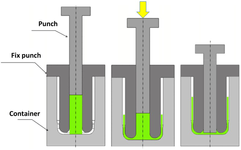
A process for applying more shear strain than with conventional backward extrusion
22
was presented by Shatermashhadi et al.
78
The new backward extrusion die set-up contains three main parts of the matrix, the moveable punch and the fix-punch, as shown in Fig. 17. In the new backward extrusion, as shown in Fig. 17, a small-diameter billet is put in the billet chamber and then the movable punch presses the billet into a die gap having two shear zones, with an angle of 90°. The lower process load and higher plastic strain of about 3.5 are important advantages of this process over the conventional method. The method was applied to commercial Al and significant grain refinement and improvement in strength were obtained by Hosseini et al.
77
A hydrostatic-based process called ‘hydrostatic back extrusion’, presented by Manafi et al.,
125
may be more suitable for processing hard-to-deform and brittle materials.126–128
Schematic of the new backward extrusion process
78
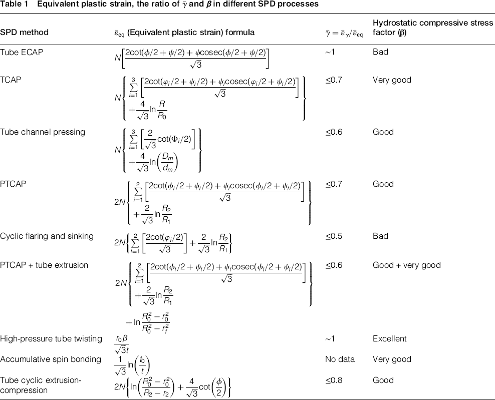
Equivalent plastic strain and hydrostatic stress
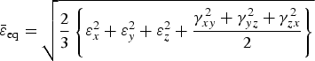
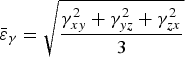
Though the effective strain is important in an SPD process, the values of the shear strain and hydrostatic stress play the main role in producing high-strength, ductile ultrafine-grained metals. Moreover, hydrostatic compressive stress could enhance the workability of metals to obtain very high plastic strains before crack initiation and propagation. To illustrate the shear part of the effective strain, the ratio of  could be defined as indicated in equations (1)–(3)

From the theory of plasticity, it can be demonstrated that the state of stress can be divided into hydrostatic and deviator stresses that represent the shear stresses within the total state of stress. Experience shows that the greater the compressive hydrostatic stress, the better the workability of a material. Compressive stresses superimposed on tensile or shear stresses during the deformation process have a significant influence on initiation and closing of small cavities and cracks (or limiting their growth), thus enhancing workability.
114
This issue can be found in equal-channel angular-pressing processing with and without backpressure. The metal could be exposed to much higher strains with backpressure compared to ECAP without backpressure.6,129 The ECAP process with back pressure (higher hydrostatic stresses) leads to production of ultrafine-grained metals with uniform microstructure and improved mechanical properties, compared with the same method without back pressure.
68
Unfortunately, this important warning was disregarded in many later studies, which utilised a ‘simplified’ die design. This led to development of many SPD methods lacking high hydrostatic compressive stresses, including such as repetitive corrugated and straightening,
130
constrained groove pressing,
131
tube channel pressing,
75
cyclic flaring and sinking,
76
equal channel angular drawing
132
and tube-ECAP.
72
For a given metal, the strain rate (process speed), process temperature and workability (which enhances the mechanical properties of the final product) is much improved if the stress state is highly compressive.
114
A general workability parameter, β, has been proposed to illustrate the ratio of hydrostatic stress to effective stress
133
and is described in equations (4) and (5)

In which,
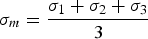
 are the principle stresses and
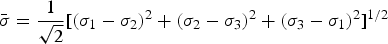
  is a hydrostatic component of the stress state. Compressive stresses are negative, and tensile stresses are positive. Here,
  is the effective stress result from equation (6)
Workability depends not only on the metal characteristics but also on the process variables, such as strain, strain rate, temperature and stress state. Using a simple calculation, it could be found that the workability parameter, β, for basic forming tests of tension, torsion and compression are, respectively, equal to 1, 0 and −1. By increasing the β value with a negative sign, the fracture strain (εf) will be increased. One of the important characteristics of SPD processes is having a higher β value with a negative sign. A larger β value with a negative sign leads to greater workability of the metal to deal with plastic strains before cracking, leading to exceptional grain refinement. Many metals that are brittle and crystalline under normal conditions, such as hcp metals, grey cast iron and molybdenum gain substantial ductility under high hydrostatic pressure and can be deformed to large strains without failure.
128
Higher β value with a positive sign leads to lower workability of the metal. The SPD process with larger, negative β values can be used to apply very large strains before fracture. Potentially leading to development of high-strength ultrafine-grained metals. When processing with SPD, grain refinement occurs and the coarse-grained structure is changed to ultrafine-grained and nanograined structures having exceptional mechanical strength. This is in accord with the well-known Hall–Petch relationship. However, there is a lower limit to the saturated grain size, dmin, a distinct condition from which the grain size cannot be further refined. The saturated smallest grain size, in processing of distinct metals and alloys, relates to the level of hydrostatic pressure, the strain state, the strain path, stacking fault energy, purity level, the strain rate and the deformation temperature.
134
The latter two factors are considered as the magnitude of the Zener–Hollomon parameter Z  . The saturation grain size can be reduced significantly by reducing the deformation temperature and level of purity.
134
Also, the smallest grain size is sensitive to the strain rate at medium temperatures, and less so at low temperatures.
134
An increase in the hydrostatic pressure leads to a decrease in the saturated smallest grain size with high-angle grain boundaries. As mentioned, this increases the workability of the material, even at room temperature, and increases the ductility of the material during processing to achieve very large strains. For example, during ‘ECAP without back pressure’ processing of copper, it is generally found that cracks appear on the billet surface after about 12 and 13 passes. However, during the ECAP process with back pressure of only 300 MPa, the same sample showed no perceptible cracking, even after 16 or more passes.135,136
. The saturation grain size can be reduced significantly by reducing the deformation temperature and level of purity.
134
Also, the smallest grain size is sensitive to the strain rate at medium temperatures, and less so at low temperatures.
134
An increase in the hydrostatic pressure leads to a decrease in the saturated smallest grain size with high-angle grain boundaries. As mentioned, this increases the workability of the material, even at room temperature, and increases the ductility of the material during processing to achieve very large strains. For example, during ‘ECAP without back pressure’ processing of copper, it is generally found that cracks appear on the billet surface after about 12 and 13 passes. However, during the ECAP process with back pressure of only 300 MPa, the same sample showed no perceptible cracking, even after 16 or more passes.135,136
 , and hydrostatic compressive stress effect (β) for different SPD processes. Whereas judgment about the β value for each process needs proper investigation of the deformation behaviour using analytical, numerical and experimental evidence, only a rough, qualitative estimation of the β value is presented here. To achieve better mechanical properties in ultrafine-grained with high-angle grain boundaries, the ratio
  and the hydrostatic compressive stress are the key parameters. However, this does not consider the manufacturing parameters and suitability for industrialisation. From Table 1, high-pressure tube twisting seems to be a more effective process for processing metals with exceptional properties, and in which both parameters
  and β have optimal values. Workability of the material is excellent and significantly large shear strain of about 24 could be applied to the material.
104
Maximum effective strains of about 8.8, 2.25, 5.6 and 7.2 were reported for the TCAP,
99
cyclic flaring and sinking,
76
tube channel pressing
75
and PTCAP
102
methods, respectively.
and β have optimal values. Workability of the material is excellent and significantly large shear strain of about 24 could be applied to the material.
104
Maximum effective strains of about 8.8, 2.25, 5.6 and 7.2 were reported for the TCAP,
99
cyclic flaring and sinking,
76
tube channel pressing
75
and PTCAP
102
methods, respectively.
Equivalent plastic strain, the ratio of and β in different SPD processes
 (Equivalent plastic strain) formula
Properties and structure of ultrafine-grained materials produced by tube SPD
Investigations of the ultrafine-grained materials properties revealed exceptional behaviour related to the specific properties associated with extreme grain refinement. Yield strength, ultimate strength, ductility and hardness are primary grain-size-dependent characteristics of a metal. The ideal structural material should combine high strength with sufficient ductility, along with high fracture toughness.
68
However, a good combination of high strength and high ductility is a very challenging task.
135
Increase in the strength by grain refinement, according to the Hall–Petch relationship ( Mechanical properties of various ultrafine-grained metals and alloys processed using SPD in which K and σ0 are material constants), could also lead to a possible decrease in ductility. High-strength and high-ductility ultrafine-grained materials are rarely produced. Metals may be strong or ductile, but rarely both simultaneously. During the last decade, reaching a good combination of high strength and high ductility has attracted much attention.135,137–140 In previous studies, the high ductility of ultrafine-grained and nanograined metals was attributed to the development of different features such as bimodal grain size distribution,
141
nanotwins formation,
142
high-angle grain boundaries with low interior dislocation densities,
140
ultrafine-grained alloy with nanosized precipitates
143
and ultrafine grained with high-angle grain boundaries.
137
However, the exact reasons for the high ductility were not clearly defined. Activation of the mentioned mechanisms may be attributed to processing factors such as hydrostatic compressive stress, pre- or post-heat treatments, strain rate, metal and alloy composition and the ratio of
in which K and σ0 are material constants), could also lead to a possible decrease in ductility. High-strength and high-ductility ultrafine-grained materials are rarely produced. Metals may be strong or ductile, but rarely both simultaneously. During the last decade, reaching a good combination of high strength and high ductility has attracted much attention.135,137–140 In previous studies, the high ductility of ultrafine-grained and nanograined metals was attributed to the development of different features such as bimodal grain size distribution,
141
nanotwins formation,
142
high-angle grain boundaries with low interior dislocation densities,
140
ultrafine-grained alloy with nanosized precipitates
143
and ultrafine grained with high-angle grain boundaries.
137
However, the exact reasons for the high ductility were not clearly defined. Activation of the mentioned mechanisms may be attributed to processing factors such as hydrostatic compressive stress, pre- or post-heat treatments, strain rate, metal and alloy composition and the ratio of  . A remarkable increase in strength, in comparison with annealed or conventionally processed samples, was reported as shown in Table 2. Limited ductility was reported for almost all tube SPD processed samples. This issue may prove valuable for future work toward achieving high-strength and ductile tubular components. This is because, in most applications, the tubes that are provided as semi-finished products are re-deformed to create industrial components using forming processes like tube hydroforming, which utilises ductile metals.
144
Table 2 displays a list of currently available data for the mechanical properties (YS, UTS, El. and hardness) of different groups of metals and commercial alloys processed via different tube SPD methods. As shown in Table 2, all tube SPD routes cause substantial improvement of strength with the loss of ductility. Only in rare cases, were both strength and ductility improved simultaneously. For example, PTCAP followed by tube back extrusion
74
of AZ31 magnesium alloy at 250°C, up to a strain of about 2.8, enhanced its ultimate strength to ∼330 MPa and 13% elongation. It seems that higher hydrostatic stress and plastic strains at the tube back-extrusion stage causes more grain refinement (to about 3 µm). The formation of equiaxed, high-angle grain boundaries is the reason for this. At the same time, from TCAP processing of AZ31 at 300°C (at a strain of about 6.6), relatively lower strength and elongation of 210 MPa and 5% were achieved, in comparison with PTCAP + tube back extrusion. Very high hydrostatic compression in tube back extrusion (compared with TCAP) might result in smaller saturated grains, which would increase strength and ductility. Figure 18 shows the final microstructures of TCAP and PTCAP + tube back extrusion processed AZ31 tubes. As shown, higher hydrostatic stress and relatively lower process temperature (with lower effective strain) produced smaller equiaxed grains.
. A remarkable increase in strength, in comparison with annealed or conventionally processed samples, was reported as shown in Table 2. Limited ductility was reported for almost all tube SPD processed samples. This issue may prove valuable for future work toward achieving high-strength and ductile tubular components. This is because, in most applications, the tubes that are provided as semi-finished products are re-deformed to create industrial components using forming processes like tube hydroforming, which utilises ductile metals.
144
Table 2 displays a list of currently available data for the mechanical properties (YS, UTS, El. and hardness) of different groups of metals and commercial alloys processed via different tube SPD methods. As shown in Table 2, all tube SPD routes cause substantial improvement of strength with the loss of ductility. Only in rare cases, were both strength and ductility improved simultaneously. For example, PTCAP followed by tube back extrusion
74
of AZ31 magnesium alloy at 250°C, up to a strain of about 2.8, enhanced its ultimate strength to ∼330 MPa and 13% elongation. It seems that higher hydrostatic stress and plastic strains at the tube back-extrusion stage causes more grain refinement (to about 3 µm). The formation of equiaxed, high-angle grain boundaries is the reason for this. At the same time, from TCAP processing of AZ31 at 300°C (at a strain of about 6.6), relatively lower strength and elongation of 210 MPa and 5% were achieved, in comparison with PTCAP + tube back extrusion. Very high hydrostatic compression in tube back extrusion (compared with TCAP) might result in smaller saturated grains, which would increase strength and ductility. Figure 18 shows the final microstructures of TCAP and PTCAP + tube back extrusion processed AZ31 tubes. As shown, higher hydrostatic stress and relatively lower process temperature (with lower effective strain) produced smaller equiaxed grains.
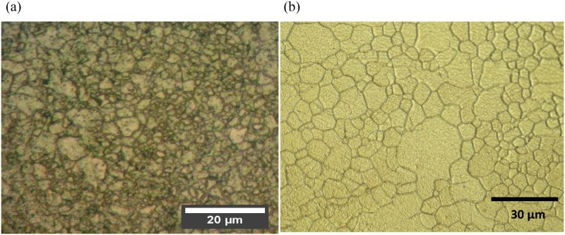
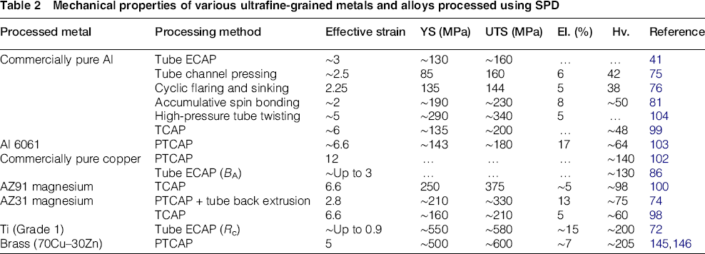
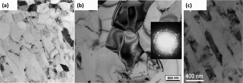
The effect of hydrostatic compressive stress on the final mechanical properties of SPD processed tubes (Table 1) could be recognised by comparison of YS and UTS processing of Al 1050 tubes, as shown in Table 2. As is seen, high-pressure tube twisting processed tubes exhibited the greatest strength. After high-pressure tube twisting, the strength of other processes is reflected in the order accumulative spin bonding, TCAP, tube channel pressing, and cyclic flaring and sinking. As is clearly seen, the tube strength may be attributed to the level of hydrostatic stress, which improved workability. In this way, it achieved higher strains before cracking and consequently formed smaller saturated grains. Figure 19 shows the microstructure of the ultrafine-grained grains (via TEM image) resulting from the TCAP, accumulative spin bonding and high-pressure tube-twisting processes. The pictures showing high-angle grain boundaries were selected from corresponding papers. As shown, the microstructure with the smallest grain size was achieved using the high-pressure tube-twisting method
104
because of its very high hydrostatic stress.
One of the other aspects of the research on SPD processing of tubes is preparing them for use as structural components in real applications. To do so, it is important to investigate their other properties such as pressure-bearing capacity (for use as high-pressure tubing), crushing behaviour with axial loading, superplastic behaviour, formability (use in hydroforming), fatigue properties and thermal conductivity. Of these, only the pressure-bearing capacity
147
and crushing behaviour
148
have been studied to date. Afrasiab et al.
148
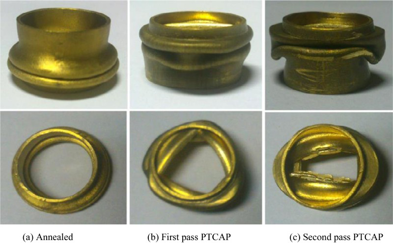
found excellent energy-absorption capacity of ultrafine-grained brass tubes produced using the PTCAP process. They showed that grain refinement of the brass tube by SPD led to change in the post-buckling modes (Fig. 20) of the thin-walled tube; and consequently, substantial increase in the energy-absorption capacity. The absorbed energy rose from 49.56 to 162.51 J and 197 J for first and second passes of processed ultrafine-grained tubes, respectively, for an annealed coarse-grained tube.
148
That work showed that nanostructured and ultrafine-grained thin-walled tubes possess an excellent energy-absorption capacity, which was increased about four times compared to their course grained counterparts.
148
This may be considered an outstanding advantage of ultrafine-grained and nanostructured tubes, over coarse-grained tubes.
Post-buckling modes of the a annealed, b and c ultrafine-grained PTCAP-processed brass tubes
148
When using a tube sample as an industrial component, the pressure-bearing capacity results from the hydro-bulging test may be more important than other uniaxial tensile behaviour. Abdolvand et al.
147
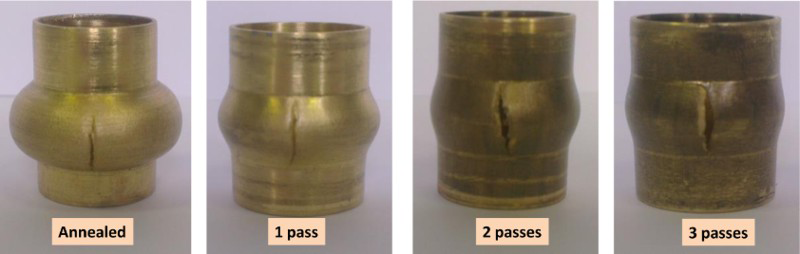
showed that the ultrafine-grained and nanograined tubes processed by the PTCAP process exhibited excellent pressure-bearing capacity in comparison with the coarse-grained counterparts. In addition, the bursting pressure of the ultrafine-grained tube was remarkably increased to 93 MPa after just the first pass of the PTCAP process (from 43.3 MPa for the coarse-grained one). The bursting pressure was 88 and 81.3 MPa, for the second and third passes, respectively, of PTCAP-processed tubing.
147
The bulge height and fractured coarse-grained and ultrafine-grained thin-walled brass tubes are as presented in Fig. 21. Less formability, although with high-pressure-bearing capacity, is seen in ultrafine-grained tubes compared with coarse-grained tubes.
a Annealed and PTCAP-processed burst tubes after a hydro-bulging test.
147
As is seen in the current review, big efforts devoted by the researchers for development of several SPD methods for producing ultrafine-grained and nanostructured tubes. Also, they attempted to mechanical and metallurgical characterise of these tubes. However, there is a big gap in the field to reach the industrial application of them. Processing of long or large diameter nanostructured tubes to a high quantity needs new innovative methods. As mentioned, processing thin-walled nanostructured tubes and also the development of creative ways for processing nanostructured microtubes with medical applications are also other demands in the field.