
Abstract
Based on AgCuNiMn alloy, Ni/Cu/AgCuNiMn high-Ni solder was designed by in-situ synthesis. The WC-6Co/In718 joint was prepared by vacuum brazing at 950 °C for 10 min. The effect of metal foil on the filler metal filling ability, microstructure and mechanical properties of the joint was studied. The microstructure evolution and strengthening mechanism of the joint brazed with Ni/Cu/AgCuNiMn solder were analysed. The results showed that Ni element mainly plays a solution-strengthening role on the joint, and improve the interface bonding strength and the strength of Ag (s, s) distributed in the centre of the brazed joint, which increased the average tensile strength by 32.4% (from 426.5 to 564.7 MPa).
Introduction
Currently, brazing tools for cemented carbides and steel are widely used in cutting, mining industry and other fields [1]. With the rapid development of modern industry, the application of cemented carbides brazing tools in some special fields, such as aerospace, polar exploration and other extreme conditions, has been paid more and more attention [2], which puts forward higher requirements for the brazing quality of cemented carbides and steel substrate. In order to solve the problem that the welding quality of cemented carbide tools brazed with conventional steel and conventional brazing filler metal under some extreme working conditions cannot meet the requirements, it is urgent to select new steel matrix materials and develop new brazing materials.
As precipitation strengthened nickel base superalloy, In718 is widely used in aerospace, petrochemical and other fields [3]. Because of its high tensile strength, yield strength, rupture strength and plasticity between −253 °C and 650 °C, connecting it with cemented carbide to give full play to their respective performance advantages is of great significance for expanding the application range of cemented carbide brazing tools; At present, the research on the brazing of superalloy mainly focuses on improving the high-temperature performance of joints, and the brazing materials used are mostly Ni-based and Cu-based solders, mainly NiCrSi and NiCrB based solders [4]. The room temperature shear strength of the In718/X-750 brazed joint with BNi-2 can reach 503 MPa [5], while the tensile strength of In718 laser brazed joint with 72AgCu filler metal is 249 MPa [6]. Compared with the brazing of superalloys, in addition to Cu-based and Ni-based brazing filler metals, there are also a large number of relevant studies on Ag-based brazing filler metals for cemented carbides. Usually based on AgCu alloy [7], Zn, Ni, Mn, Ti, Pd and other alloy elements are added to improve the performance of brazing joints [8]. The addition of Ni element can inhibit the migration of Co in cemented carbides [9], and enhance the wetting flow ability of brazing filler metals on cemented carbides [10]. Ni and Mn elements can improve the solder alloy's heat and corrosion resistance [11]. However, there are few reports on the brazing of cemented carbides and superalloys. Wang et al. [12] found that the joint shear strength was 127.5 ± 2.1 MPa, and the fracture showed brittle fracture characteristics through vacuum brazing YG8 and In718 with AgCuNiLi filler metal. Given the above situation, we find that the research on brazing of cemented carbide and superalloy is lack, besides there is no solder design standard for reference, and the strength of the brazed joint is low. So it is of great significance to design and develop new high-strength brazing materials to braze cemented carbides and superalloys.
Based on AgCuNiMn filler metal and referring to the method of in-situ synthesis [13], this study prepared Ni/Cu/AgCuNiMn solder of high nickel content. WC-6Co and In718 were brazed with the two kinds of solders to combine the excellent properties of cemented carbides and superalloy. Through comparative analysis of the microstructure and tensile strength of brazed joints, the microstructure evolution and strengthening mechanism of brazed joint with Ni/Cu/AgCuNiMn solder were revealed, which provides a certain reference value for the brazing between cemented carbides and superalloy.
Materials and methods
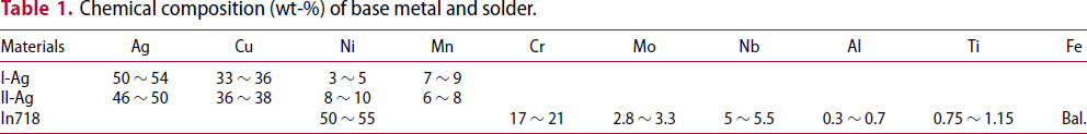
Chemical composition (wt-%) of base metal and solder.
Brazing was carried out in a tube furnace under a vacuum of 7 × 10⁻³ Pa at 950°C for 10 min. Before brazing, the contact surfaces of base materials were polished with diamond paste, the solder surface was polished with sandpaper to remove oxide skin, and the metal foil was cleaned with 5% hydrochloric acid. Finally, specimens were cleaned by acetone in an ultrasonic bath together with the filler metals. There are two main types of brazing samples, as shown in Figures 1 and 2, respectively. Figure 1 is the test sample of filler metal filling ability. Figure 1(a) is the schematic diagram of solder joint filling capacity sample. Figure 1(b) shows the assembly drawing of the sample with metal foil. Because the thickness of metal foil is 0.01 mm, the slot width of the simple with metal foil is 3.20 mm.
Schematic diagram of solder filling ability sample: (a) The dimensions of solder filling ability sample, (b) assembly diagram of sample with metal foil.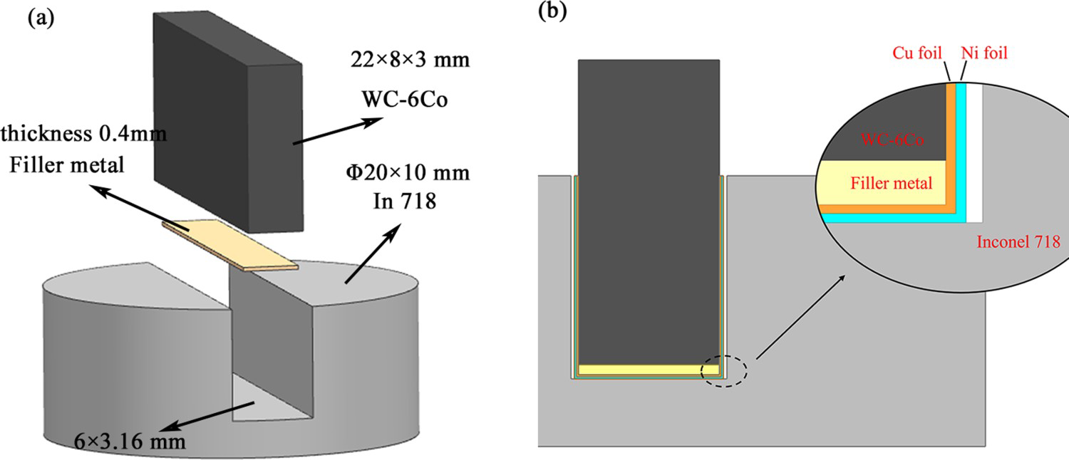
The dimension of tensile strength testing sample is shown in Figure 2(a), the diameter of the straight section of the sample is 5 mm and the sample assembly is shown in Figure 2(b). After brazing, a small interface sample was cut from the sample by electric spark cutting. After inlaying and polishing, the microstructure of the brazing seam was observed by SEM and EDS energy spectrum analysis was conducted. The tensile strength of the joint was tested by MTS tensile tester at a tensile speed of 1 mm/min. The microhardness of each phase in the brazing seam was tested by a microhardness tester. In order to study the strengthening effect of the joint, the software application Image pro plus was used to calculate the area of different microstructures.
Schematic diagram of brazing sample: (a) The dimensions of solder and brazing sample and (b) assembly diagram.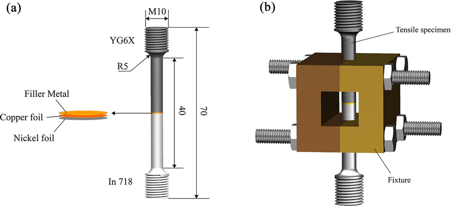
Results and discussion
Microstructure
The microstructure morphology of the brazed joint with I – Ag solder and II – Ag solder is shown in Figure 3(a,b). Metallurgical bonding without any defects was achieved for the brazed joint. The EDS result of representative areas of the brazed joint is shown in Table 2.
Microstructure of brazed joint: (a) SEM image of I – Ag solder brazed joint (b) SEM image of II – Ag solder brazed joint (c) The magnified image of the interface between II – Ag solder and In718. Chemical composition (wt-%) of regions marked in Figure 3.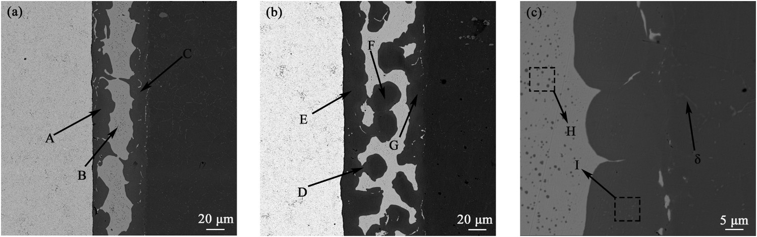
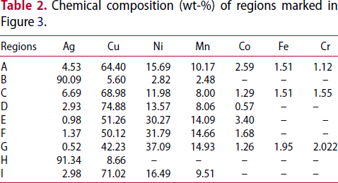
The composition of region A and C is similar, which is enriched with Cu, Ni, Mn and a small amount of Fe, Co, Cr; the phase is considered to be Cu(s,s). The content of Cu, Ni and Mn at region D is similar to that at A and C, but the content of Co is low, and no Fe and Cr is found. The average mass fraction of Ni in E, F and G is 33.05%; according to the research of Hongsheng Chen et al. [14], this phase is considered to be (Cu, Ni) (s, s). Fine Cu-rich phases are dispersed in the Ag (s, s) matrix at region H, and fine Ag-rich phases are dispersed in the Cu (s, s) matrix at region I. δ is the strengthening phase [15] distributed at the grain boundary in the In 718 matrix. The influence of δ phase distributed at the solder/In 718 interface needs to be further studied.
The difference between the microstructure of two brazed joints is reflected in the distribution of Cu-rich phase. In addition to the distribution along the interface on both sides, the Cu-rich phase in the brazing seam of II – Ag solder is largely distributed in the Ag matrix in the centre area of the joint. The proportion of Cu-rich phase in the brazed joint is measured with image pro plus. The results are shown in Figure 4. The proportion of Cu-rich phase in the brazed joint of II – Ag solder is 11% higher than that of I – Ag solder (from 57.8% to 68.8%). The increase of strengthening phase improves the overall strength of the joint to a certain extent.
The proportion of Cu-rich phase in brazing seam.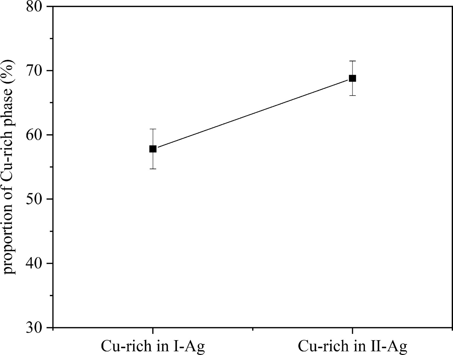
The EDS map scanning results of the II – Ag solder joint is shown in Figure 5. In the in situ synthesis process, the Cu, Ni interlayer and the solder matrix have had sufficient metallurgical reaction. It can be seen in Figure 5(c,d) that (Cu, Ni) (s, s) occupy most of the area of the Cu-rich phase, while Cu(s, s) is distributed in the peripheral area of (Cu, Ni)(s,s), making the composition of copper and nickel at region D is different from that of region E, F and G. The distribution of Mn element is consistent with that of Ni element, which is shown in Figure 5(e). In Figure 5(f), it can be seen that during the brazing process, long-range diffusion of co occurs and it is enriched in the Cu-rich phase.
EDS elemental mapping of II – Ag solder brazed joint (a), (b) Ag, (c) Cu, (d) Ni, (e) Mn and (f) Co.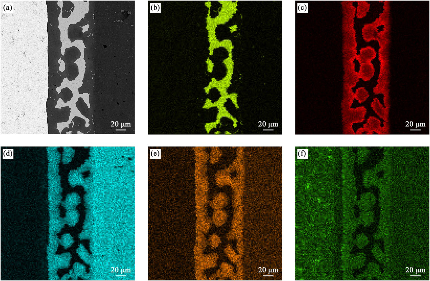
Flow ability of solder
Figure 6 shows the macroscopic appearance and microstructure of the welded sample. It can be seen from Figure 6(a) that the filler metal of the brazed sample without metal foil can not completely fill the gap, and the climbing height is 4.5 mm (the total height of the gap is 6 mm). It can be seen from Figure 6(b) that when the metal foil is added to the sample, the filler metal can fill the gap well, indicating that in the brazing process, there is an in-situ reaction between the filler metal and the metal foil, leading the filler metal to climb up to fill the gap, Namely, the solder form of Ni/Cu/AgCuNiMn can enhance the wetting and spreading ability of the solder.
Post-welding appearance of caulking specimen: (a) appearance of sample without metal foil, (b) appearance of sample with metal foil.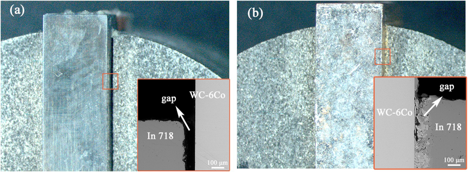
Mechanical properties of brazed joint
The microhardness of the phase in the brazed joint of I – Ag solder and II – Ag solder is shown in Figure 7(a,b), respectively. From the WC-6Co to filler metal, the hardness of WC-6Co near the interface is slightly lower than that of the distal matrix and decreases sharply when reaching the Cu-rich phase at the interface of WC-6Co/solder. The hardness of Ag (s, s) at the centre of the brazing seam is the lowest. As is shown in Figure 7, the hardness of Cu-rich phase at the interface on both sides in the same brazed joint is almost the same. As is shown in Figure 7(b), the hardness difference in the Cu-rich phase is related to the proportion of (Cu, Ni) (s, s) and Cu (s, s), and the hardness value is relatively high when (Cu, Ni) (s, s) dominates. The average hardness of the Cu-rich phase in the brazed joint of II – Ag solder is higher than that of I – Ag solder, because the average content of Ni element in Cu-rich phase of the II – Ag solder brazed joint is higher than that of I – Ag solder. The slight decrease in hardness value near the interface of cemented carbide may be related to the diffusion behaviour of Co in WC-6Co because the diffusion migration of Co element will change the structure of WC-Co [16].
Microhardness of different phases:(a) I – Ag solder brazed joint and (b) II – Ag solder brazed joint.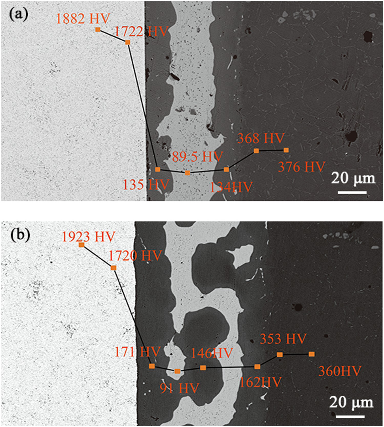
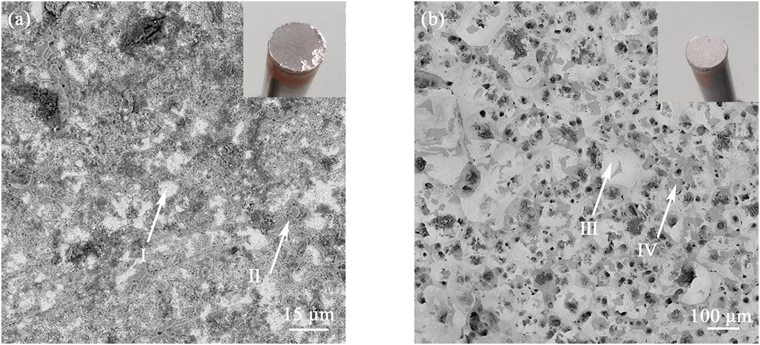
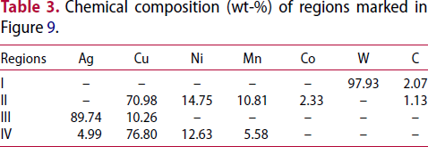
The tensile strength of the brazed joint is shown in Figure 8. When the mass fraction of Ni in the solder increases, the average tensile strength of the sample increases by 32.4% (from 426.5 to 567.7 MPa). Figure 9(a,b) showed the fracture surface of the I – Ag and II – Ag solder brazed joint, respectively. The typical regions in Figure 9 were marked region I, II, III, IV, the composition of each region was shown in Table 3. Region I was WC, region II and IV were Cu(s,s), and region III was Ag(s,s). From the phase composition of the fracture, it can be seen that the weak area of the brazed joint of I – Ag solder was at the interface between WC-6Co and solder, and the weak area of the brazed joint of II – Ag solder was the Ag-rich area in the centre of the brazed joint. According to [9], increasing the Ni content in the solder can weaken the Co-poor effect at the cemented carbide near the interface, and the increase of strengthening elements such as Ni and Mn in the Cu-rich phase at the interface enhances the interface bonding strength.
Tensile strength of the joints brazed with I - Ag solder and II – Ag solder. Fracture micro-morphology of I – Ag solder brazed joint (a) and II – Ag solder brazed joint (b). Chemical composition (wt-%) of regions marked in Figure 9.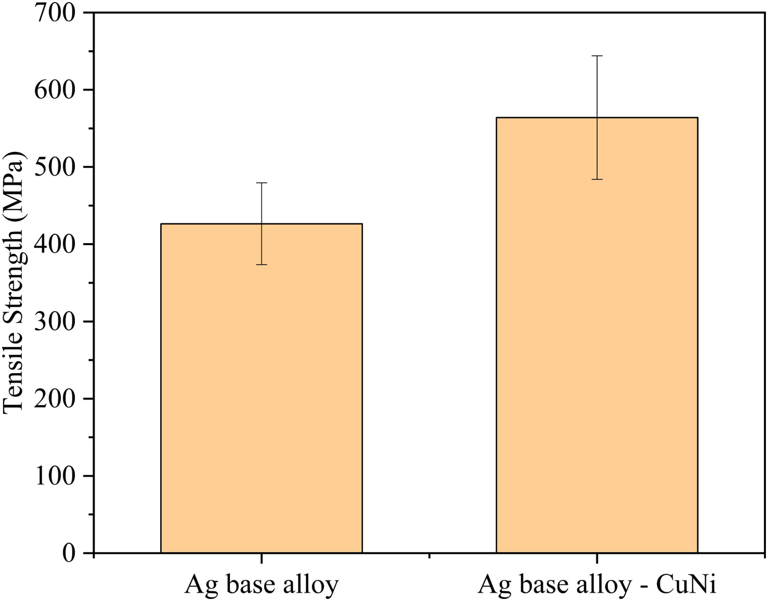
Discussion
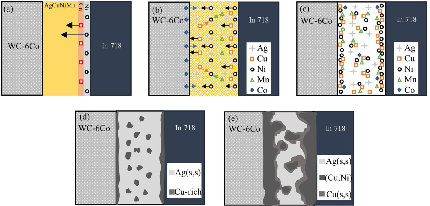
The reaction of Cu and Ni foil with solder and base metal during brazing is mainly divided into two stages: solid-phase diffusion and liquid-phase diffusion [17]. According to the concentration gradient and alloy phase diagram between the main constituent elements of the brazed joint, and referring to the microstructure composition and morphology of the brazed joint, the formation and evolution of the microstructure of the brazed joint with Ni/Cu/AgCuNiMn solder can be divided into the following stages, as shown in Figure 10.
(I). Solid phase diffusion stage. With the increase of brazing temperature, the contact between Cu foil, Ni foil and solder is closer, a weak solid phase diffusion reaction occurs between each part, as shown in Figure 10(a). (II). Liquid diffusion stage. With further increase in temperature, the original solder gradually melts, while Cu and Ni foil are gradually dissolved by liquid solder. The diffusion among elements is strongest when the temperature reaches the brazing temperature. As concentration gradient is the main driving force for element diffusion, Cu and Ni enriched at In718 side interface will diffuse to the centre of brazing seam and WC-6Co side, while Co will diffuse to the brazing seam. According to the alloy phase diagram, Ni can form a continuous solid solution with Cu, Co and Fe, and Gibbs free energy for forming Ni–Co system is lower than that of Ni–Cu [18]. The continuous solid solution can also be formed between Cu, Ni and Mn [19], so Cu, Mn, Co and other elements will aggregate to Ni, as shown in Figure 10(b). Under the concentration gradient of Ni and attraction of Co, Ni at the interface of In 718/solder is enriched at the interface of cemented carbide/solder [18], while Cu and Mn in the filler metal are also concentrated at the interface on both sides under the attraction of Ni. Cu, Ni, Mn and other elements in the central area of the brazing seam also concentrated together [20], as shown in Figure 10(c). (III). Solidification stage. During the cooling solidification process, elements such as Cu, Ni and Mn at the interface crystallise along the interface to form a continuously distributed Cu-rich phase, and the above elements in the centre of the brazing seam form a Cu-rich phase in the brazing seam, as shown in Figure 10(d). According to the phase diagram of Cu–Ni–Mn ternary alloy [20], the melting point of Cu–Ni–Mn solid solution increases with the increase of Ni content, so the high melting point (Cu, Ni) (s,s) precipitated first. After most of the Ni precipitated, the relatively low melting point Cu (s,s) continues to precipitate along the (Cu, Ni)(s,s). With the solidification process, the Cu-rich phase at the interface continues to grow, gradually contacts with some Cu-rich phases in the central area of the brazing seam, and then the low melting point Ag (s, s) solidifies and precipitates in the framework of the Cu-rich phase. Finally, the microstructure morphology as shown in Figure 10(e) formed. Schematic diagram of microstructure evolution of in-situ synthetic solder joints: (a) weak diffusion at the beginning, (b) diffusion of elements at high temperature, (c) the distribution of elements in the diffusion process, (d) initial stage of solidification and (e) microstructure of brazed joint.
When the size of the metal foil is larger than the size of the solder, according to the above in-situ reaction mechanism, when the dissolution and diffusion reaction occurs between the metal foil and the original solder, the metal foil can promote the spread of the solder due to the influence of the element diffusion behaviour and the affinity between the elements. as shown in Figure 6.
The difference in mechanical properties of brazed joints is determined by the composition and distribution of microstructure. It can be seen from Figure 4 that the proportion of the strengthening phase (Cu-rich phase) in the brazed joint of II – Ag solder is higher than that of I – Ag solder and the distribution of Cu-rich phase in the Ag matrix distributed in the centre area of the brazed joint strengthens the relatively soft Ag matrix. It can be seen from Table 2 that the increase in the content of solid solution strengthening elements Ni and Mn in the Cu-rich phase of II – Ag solder brazed joint increases the proportion of (Cu, Ni) (s, s), and the Ni and Mn atoms dissolved in the Cu matrix cause a substantial solid-solution strengthening effect in the Cu–Ni–Mn alloys [21]. Because of its continuous distribution along the interface on both sides, the interface bonding strength between the base metal and solder is improved so that the average tensile strength of the sample brazed by II – Ag solder is higher than that of the sample brazed by I – Ag solder.
Conclusion
In this study, Ni/Cu/AgCuNiMn solders were fabricated by the in situ synthesis method based on AgCuNiMn solders. The microstructures and mechanical properties of WC-6Co/In718 joints brazed with two kinds of solders were studied to analyse the effects of Ni/Cu/AgCuNiMn solders on the microstructure evolution and properties of brazed joint. Based on the results obtained, the following findings can be concluded:
In Ni/Cu/AgCuNiMn brazed joint, the proportion of Cu-rich phase and the (Cu,Ni)(s,s) of Cu-rich-phase is higher than that of the original solder brazed joint, and in addition to continuous distribution along the interface on both sides, the Cu-rich phase is also distributed in the Ag(s,s) matrix distributed in the centre of the braze joint. The form of Ni/Cu/AgCuNiMn filler metal can improve the wetting and spreading ability of the original filler metal, so that the filler metal can also braze the joint well at a large gap. The average hardness of Cu-rich phase in brazed joints with Ni/Cu/AgCuNiMn solder is higher than that of the original filler metal, and the average tensile strength of the joint is 32.4% higher than that of the original filler metal, increasing from 426.5 to 564.7 MPa. The Cu-rich phase distributed in the Ag(s,s) matrix strengthens the Ag(s,s), and the continuous distribution of (Cu, Ni) (s, s) with high Ni and Mn along both sides of the interface enhances the interface bonding strength between the base metal and solder. Under the combined effect of the two strengthening effects, the tensile strength of the brazed joint with Ni/Cu/AgCuNiMn solder is improved.
Footnotes
Acknowledgements
We gratefully acknowledge support for this work was supported by Key Research and development projects in Henan province (221111520100).
Disclosure statement
No potential conflict of interest was reported by the author(s).
Data availability statement
The data that support the findings of this study are available from the corresponding author, [SJ Z], upon reasonable request.