
Abstract
A novel approach for predicting the intermetallic compound (IMC) formation during friction stir welding (FSW) of AA6061 to commercially pure copper has been developed, in addition to their effect on mechanical properties. The temperature distribution of the aluminium to copper weld nugget determined by a finite element model, the use of an Al–Cu phase diagram and the elemental concentration of copper and aluminium in the weld nugget have been combined to predict and validate several IMCs present in the different zones of the weldment. The results of performing butt-welding of these dissimilar metals using the FSW process demonstrated that the highest ultimate tensile strength of 194.5 MPa was achieved at 1500 rev min−1 tool rotational speed, 100 mm min−1 traverse speed and a zero-tool offset.
Keywords
Introduction
Dissimilar welded joints between copper and aluminium offer an attractive solution in engineering systems, where the partial replacement of copper with aluminium maintains the electrical properties of the former in parallel with the lower cost and light-weighting benefits of the latter. Such applications include, but are not limited to, shell and tube heat exchangers, electrical connections such as capacitor windings and transformer conductors [1, 2]. Despite the obvious benefits of this partial replacement approach, a range of challenges exist due to the mismatch in the thermal, chemical, and metallurgical properties of each metal. In the early 1990s, a solid-state friction stir welding (FSW) process was developed for joining difficult to weld metals and alloys. In the case of dissimilar welding, FSW has many advantages over fusion welding techniques; these include reduced environmental impact, elimination of solidification problems, such as cracking and porosity formation, lower heat input and less distortion [3].
Nevertheless, challenges arise when joining aluminium to copper using FSW, particularly the formation of intermetallic compounds (IMCs) at the interface zone and weld nugget. There have been some attempts to predict and control the formation of IMCs in dissimilar friction stir welds; Mishra et al. [4] proposed the first approach for predicting the IMCs in such cases. By assuming a simple material volume under the FSW tool, they [4] qualitatively showed that, with the aid of a phase diagram, IMC formation can be predicted if the tool offset is carefully controlled. However, as their approach [4] took no account of the thermo-mechanical effect during the FSW process, the ability to accurately predict the IMC formation is questioned [2]. Additionally, the material volume beneath the FSW tool is known to form a simple parallelepiped shape which was not accounted for in their [4] work. More recently, Shailesh et al. [5] advanced the work of Mishra et al. [4] by assuming a cylindrical material volume under the FSW tool. Although the derived equations of Shailesh et al. [5] were valid and logically accepted to represent the material volume under the FSW tool, there was again an absence of accurate thermo-mechanical data to fully support their method.
In addition to the above predictive approaches, some attempts have been performed to understand the formation of these IMCs as well as their effect on the joint mechanical properties. Ouyang et al. [6] studied the microstructural evolution during FSW of AA6061-T6 to copper, where the dissimilar weld nugget exhibited several IMCs such as Al2Cu, AlCu and Al4Cu9. In their work [6], thermocouples were located at 2, 4, and 6 mm from the pin area and towards the aluminium (the retreating side). It was found [6] that the measured temperature of the AA6061 reached 580°C, which is greater than the melting temperature at the eutectic composition of an Al–Cu binary alloy. The authors [6] proposed that these IMCs evolved on the basis of two different phenomena, these being (a) the constitutional liquation that governs the formation of aluminium-rich phases (Al/Al2Cu eutectics, Al2Cu and AlCu), which is due to their solidified morphology, and (b) their relatively lower melting temperature. In contrast, the solid-state diffusion phenomenon was claimed to control the formation of the copper-rich intermetallic structures in the weld zone (Cu(Al) and Al4Cu9). This can be attributed to the thermo-mechanical effect of FSW at the weld nugget, where the melting temperature of Al4Cu9 (1030°C) is higher than the peak temperature during FSW. It was concluded [6] that the existence of these brittle IMCs created a high level of disparity in the mechanical properties of the weld. In their work [6], there was an absence of the resultant high strain rate effect in the evolution of the relatively lower melting temperature IMCs (Al2Cu and AlCu), as the thermo-mechanical effect of FSW can also explain the formation of these IMCs.
More recently, Galvao et al. [7] claimed that the IMC formation in dissimilar FSW of aluminium to copper can only be explained by the thermo-mechanically activated solid-state diffusion phenomenon. Unlike the approach of Ouyang et al. [6], Galvao et al. [7] proved the absence of solidification structures in both the aluminium- and copper-rich sides and reported that the resultant high strain rate during the FSW process facilitates the formation of Al2Cu, AlCu and Al4Cu9, an approach that has also been supported in other recent publications [8, 9]. Further, Xue et al. [10] and Galvao et al. [11] investigated the influence of process parameters on the evolution of IMCs during FSW of aluminium to copper. They claimed that the location of each material with respect to the advancing side (AS) of the FSW tool, as well as the tool rotational speed relative to the welding speed (ω/v) ratio, have a significant effect on the IMC formation and subsequently the joint mechanical strength. Other published work [12, 13] demonstrated that a thin continuous IMC layer in aluminium to copper could significantly improve the mechanical properties of the joint in which the predominant IMCs in the weld nugget were Al2Cu and Al4Cu9 and that their presence resulted in a tensile strength equating to 80% of the aluminium base alloy.
On the other hand, Karrar et al. [14] reported on the advantages of placing the softer material on the advancing side. Their work established the validity of placing the softer material (AA5083) on the advancing side to achieve relatively higher mechanical properties, i.e. 94.8% joint efficiency, which agreed with the work of Tan et al. [15]. Although Karrar et al. [14] qualitatively identified the direct benefit of the combined presence of IMCs and the composite-like microstructure on the joint mechanical strength, there was a lack in quantifying these IMCs as well as predicting their presence relative to the FSW parameters, i.e. (ω/v) ratio. Overall, researchers [3-16] have not definitively demonstrated the negative or positive role played by the IMC particles. Furthermore, there is a lack of understanding towards the evolution of these IMCs during the FSW process of aluminium to copper. Additionally, there is a clear lack of reporting on the quantitative nature of the IMCs in the weld nugget.
The primary purpose behind the current study is to achieve better and consistent weld quality by controlling the IMC formation. Furthermore, as it is expected that IMC formation during FSW is intrinsically based on a thermo-mechanical phenomenon governed by the combined effect of temperature, plastic deformation, and material mixing, it is clear that the prediction of any evolved IMCs during FSW of aluminium to copper must be based on accurate numerical thermo-mechanical data combined with phase diagram information.
Hence, the current systematic study presents a highly novel approach for accurately predicting the IMC formation in FSW of dissimilar AA6061 to copper based on three related criteria as follows; (1) the thermal outputs from the finite element model developed by Al-Badour et al. [17], (2) the use of the Al–Cu phase diagram to identify the evolved IMCs as a function of the thermal outputs and (3) a robust microstructure and property evaluation to validate the IMC formation predicted from criteria (1) and (2), allowing the mechanical properties of the joint to be determined as a function of the type of IMCs that are formed.
Methodology
Numerical model development
A coupled Eulerian–Lagrangian (CEL) model [15] is applied to simulate the FSW process of joining AA6061 to copper. For the multi-layers of complexity to formulate the problem, CEL is the most appropriate modelling solution [18-20]. CEL captures the severe plastic deformation by avoiding the distortion of the mesh during the process, where the material flows through a stationary mesh in the Eulerian domain. The Abaqus Explicit Solver environment is used to implement and solve the model.
A geometrical model of 300 × 50 × 3 mm3 (Eulerian domain) is assumed with three distinctive areas in this domain; the copper plate (retreating side (RS)), the aluminium plate (AS) and a void layer of 1 mm in thickness to visualise the flash formation during the process. A simple, featureless FSW tool pin of 4.5 mm diameter and shoulder of 18 mm diameter are considered as a Lagrangian rigid body domain; thus, all the physical properties and boundary steps are assigned to a unique reference point.
A fine biased seeding mesh is considered along and around the FSW shoulder area (region of high plastic deformation), where the mesh becomes coarser towards the Eulerian domain sides. Multi-layer thermally coupled elements are assumed for the Eulerian plates.
Unlike the CEL model reported by Al-Badour et al. [17], the FSW tool herein is assumed to rotate and traverse along the Eulerian domain, while this domain is only constrained against the velocities and displacements on its sides. Figure 1(a) shows the typical boundary conditions for Eulerian and Lagrangian domains as well as the dissimilar materials placement where Figure 1(b) illustrates the finer mesh within the shoulder area. The initial temperature for all the model parts is assumed to be uniform and equal to 25°C.
(a) Applied boundary conditions and placement of each material. (b) Mesh in the vicinity of the FSW shoulder area.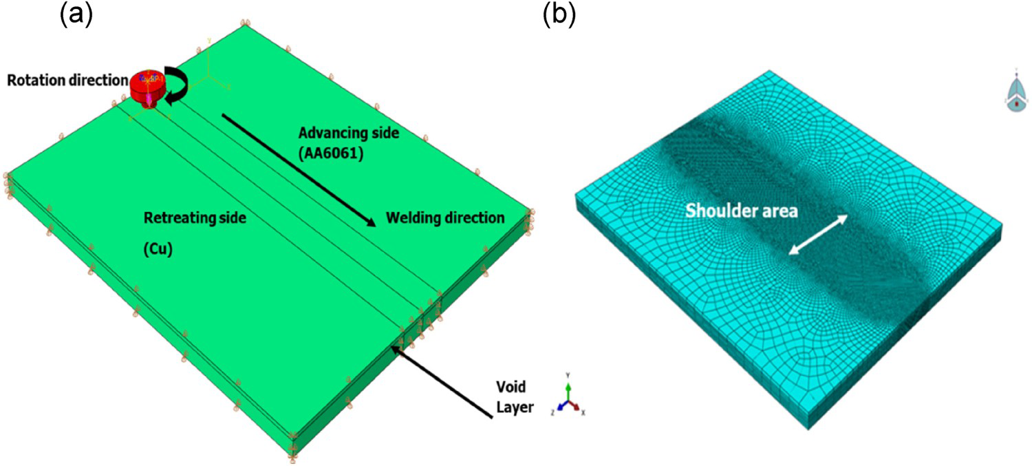
Material properties
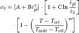
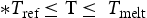
Due to plastic deformation in the FSW zone at high temperatures and strain rates, the Johnson–Cook's constitutive model [21], shown in Equation (1), is considered to formulate the plasticity of the dissimilar materials. Thus, the material flow/yield stress
 is described as a function of plastic strain, strain rate and temperature.
 ,
,
 is the material solidus temperature,
 ,
,
 and
and
 are the effective plastic strain, effective plastic strain rate and normalising strain rate, respectively).
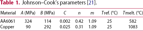
Johnson–Cook's parameters [21].
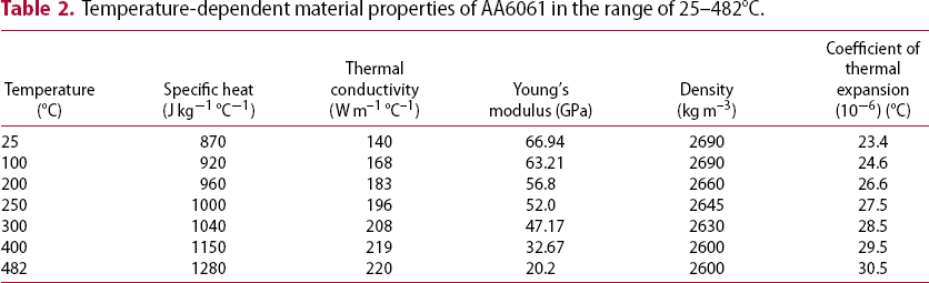
Temperature-dependent material properties of AA6061 in the range of 25–482°C.
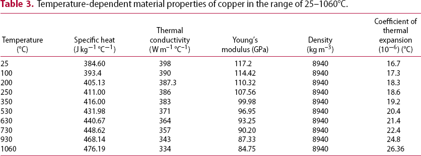
Temperature-dependent material properties of copper in the range of 25–1060°C.
Friction coefficient
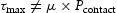
Defining the contact condition between the FSW tool and the dissimilar materials is complex to formulate. Assuming sticking boundary conditions [22], the coefficient of friction as a function of pressure and slip rate [23] or Coulomb's law [15] are the main approaches to simulate the interaction condition between the FSW tool and the workpiece. In the present work, the modified friction law described by Shokri et al. [24] is considered to couple the interaction between the Lagrangian (tool) and Eulerian (aluminium and copper) domains, while both sticking and slipping conditions can be involved. An intermediate value of
 is chosen where, above this value, the sliding conditions are no longer applicable, i.e.
 ,
,
 and
and
 are the coefficient of friction and contact pressure, respectively. The
 value is calculated from the Von-Mises relationship in Equation (2) by considering that:
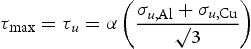
 are the ultimate shear stress and ultimate material strength and
 is the material volume fraction, equal to 0.5 at the joint line. An average value of 0.5 for the friction coefficient
 is assumed for the interaction between aluminium, copper, and steel (FSW tool) during the sticking condition where no voids are formed.
Experimental methodology
Materials and FSW process details
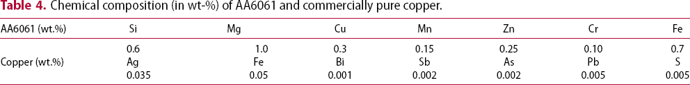
Chemical composition (in wt-%) of AA6061 and commercially pure copper.
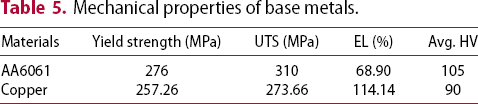
Mechanical properties of base metals.
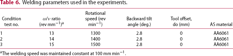
As FSW is an asymmetric process, the positioning of the dissimilar materials, with respect to the tool advancing and rotational speed, plays a major role in the resultant joint integrity [1, 2]. In this work, defect-free welds were achieved by placing the softer material (AA6061) at the advancing side (AS) while the FSW tool was centred at the seam line, as illustrated in Figure 2. The considered welding parameters can be found in Table 6, where the tool rotational speed was varied while fixing the other parameters, i.e. tool traverse speed and tool title angle.
(a) Weld configuration and experimental set-up (300 × 50 × 3 mm³). (b) The measurement positions of thermocouples imbedded into AA6061 (As) and copper (Rs). Welding parameters used in the experiments. The welding speed was maintained constant at 100 mm min−1.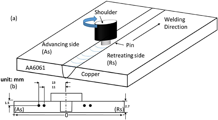
The temperatures in the weld zone were measured by K-type thermocouples embedded at different positions (11–13 mm) from the joint line, i.e. 2–4 mm from the shoulder surface. A series of holes (1.5 mm in diameter) were drilled from the side of AA6061 (As) and the side of copper (Rs), as shown in Figure 2(b). These holes were located at the mid-region (i.e. 150 mm from the starting point) of the plate length to allow for steady-state FSW conditions to be developed. Figure 3(a,b) shows a transverse cross-section and a top view of the relative location of the FSW tool at 0 mm and d mm tool offset, respectively.
(a) Transverse and top view showing the symmetrical location of the FSW tool at 0 mm tool offset. (b) The location at d mm tool offset.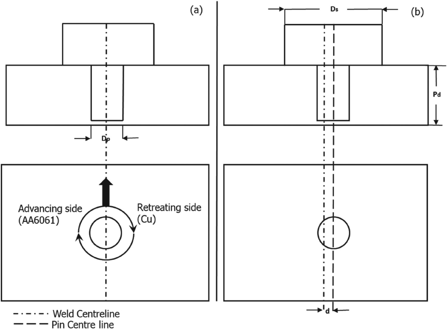
Metallographic examination
The generated welded joints were sectioned and prepared for metallographic examination. A two-stage etching process was deployed to allow high-resolution optical and scanning electron microscopy to be undertaken. Energy dispersive spectroscopy (EDS) was used to analyse the weld zone composition. To study the developed phases and quantify the amount of IMCs in the weld zone, the Topas Rietveld X-ray diffraction (XRD) method was implemented. The XRD analysis was performed at a scanning rate of 0.02 deg step−1 within the range of 20° < 2θ < 100°, with a 40-mA operating current, 40-Kv voltage and 1.5406-Å Cu Kα radiation.
Mechanical testing
The joint mechanical strength was evaluated by testing sub-size specimens across the weld zone of each welded sample in accordance with ASTM E8 [25], details of which are shown in Figure 4
Tensile test specimen dimensions per ASTM E8 standard [25].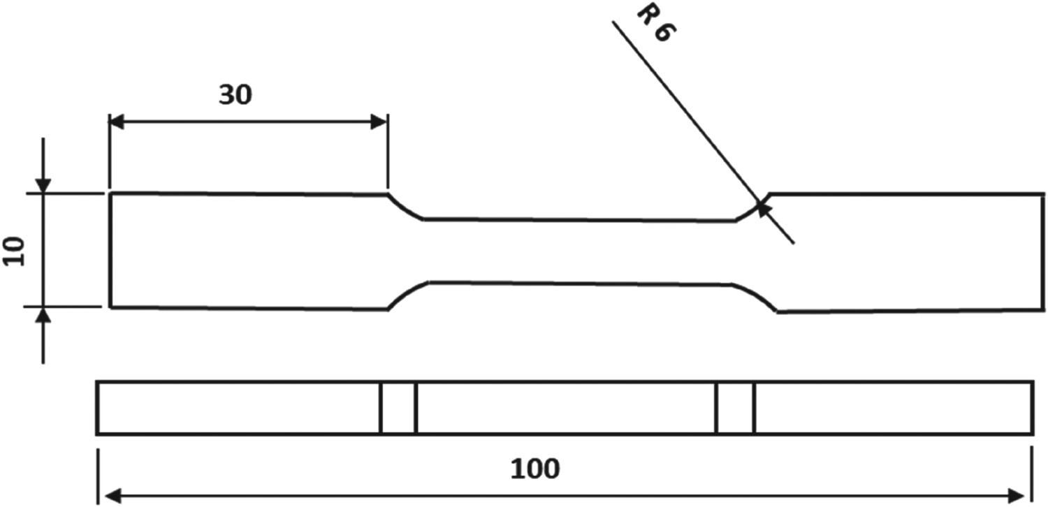
Results and discussion
Thermal model validation
Quantitatively, the nodal temperature history from the CEL model is compared to the experimental data at distances of 11 and 13 mm from the weld centreline, and towards both the AA6061 (AS) and copper (RS). To ensure a high degree of accuracy, care is taken by running the model exactly at the same welding parameters in test no. 2 (Table 6) of 1400 rev min−1, 100 mm min−1 and 0 mm tool offset. Figure 5(a,b) reveals the CEL model temperature history accompanied with the experimental temperature measurements recorded by thermocouples towards AS and RS, respectively. As shown from Figure 5, the CEL with a modified friction law results in good agreement with the experimental data. It is also observed that the AS (AA6061) temperature is higher than the RS (copper) due to the fact that copper dissipated heat more rapidly than aluminium. This asymmetric behaviour of the temperature distribution was previously reported in a separate publication [11].
Calculated vs. measured temperature of 1400 rev min−1, 100 mm min−1 and 0 mm tool, at different positions from the pin centre toward both (a) the AS (AA6061) and (b) the RS (copper).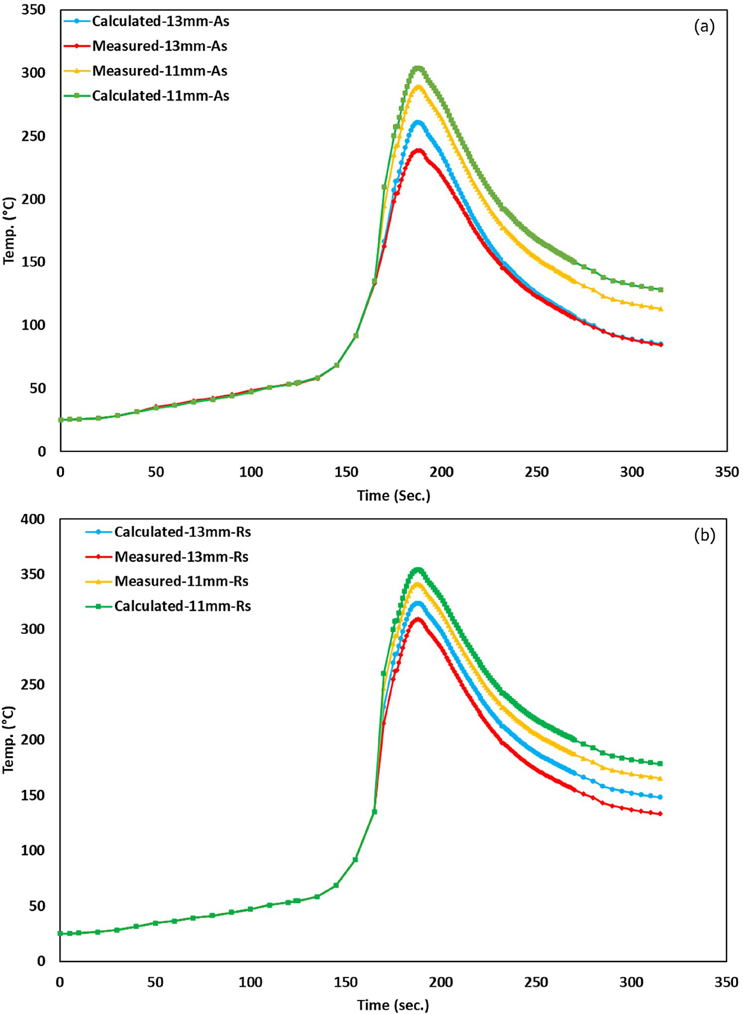
In the dissimilar FSW of aluminium to copper, the formation of IMCs is related to the welding parameters, i.e. frictional heat input (ω/v) ratio and tool offset. The formation of these IMCs greatly affects the joint quality in terms of mechanical strength, morphology, and defect formation [2, 4]. Thus, any attempts to control or inhibit the IMC evolution along the weld joint will significantly improve the joint quality. Hence, a qualitative analysis for the IMC formation based on the CEL model results together with the Al–Cu binary system is presented. The effect of rotational speed (ω/ν ratio), material placement, tool pin offset and the peak temperature are all considered in this analysis. The qualitative description for the IMC formation in FSW of aluminium to copper, based on the work of Shailesh et al. [5], has been modified and developed herein for use on aluminium to copper. Figure 6 shows the material volumes of AA6061 and copper in the case of 0 mm tool offset (b), d mm tool offset (c). Where the total volume swept by the tool is given by Equation (3), the volume of copper swept by the pin (
Schematic of the material volume at different tool offsets. ) can be expressed by Equation (5), hence the ratio of copper swept volume over the total volume can be determined from Equation (6).
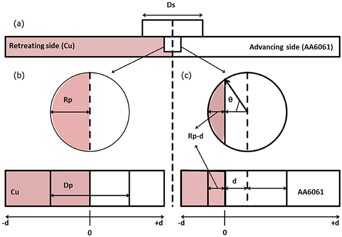
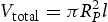

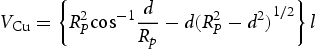
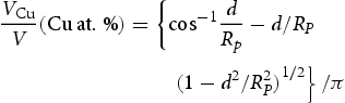

Figure 6 and Equation (6) demonstrate that the tool offset affects the volume fraction of the total weld nugget, a prerequisite for IMC formation. Table 7, which summarises the predicted Al–Cu phases at different tool offsets towards both AA6061 and copper side, is constructed based on the Al–Cu equilibrium phase diagram, allowing the predicted phases to be determined based on the volume fraction of aluminium and copper (Figure 7).
Al–Cu equilibrium phase diagram. Predicted phases at different tool offset.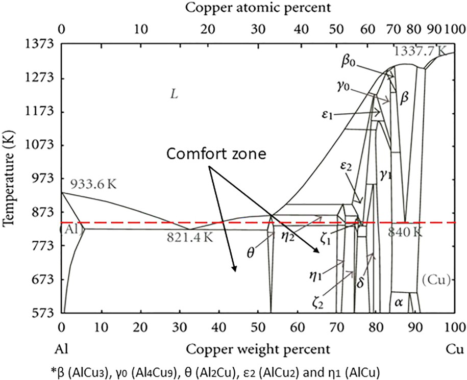
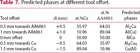


The generic approach to control the IMC formation at the weld nugget is by positioning the tool in a way that keeps the compositions of aluminium to copper within the comfort zone, i.e. reduced possibility of IMC formation below the resulting temperature during FSW of AA6061 to copper [10]. Thus, the third aspect of this qualitative analysis is the temperature profile at the weld nugget. Figure 8(a) exhibits the top view of the temperature distribution at the welding stage in Kelvin at 0 mm tool offset. The same figure also shows that the peak temperature predicted by the CEL model is always lower than the aluminium melting temperature and within the plasticised zone. Figure 8(b,c) presents cross-sectional views of the temperature profiles at 1400 rev min−1 – 100 mm min−1 and 0 mm tool offset as well as 1500 rev min−1 – 100 mm min−1 and 0 mm tool offset.
(a) Top view of temperature profile at 1400 rev min−1 and 100 mm min−1, (b) cross-section view of temperature profile at 1400 rev min−1 and 100 mm min−1, (c) cross-section view of temperature profile at 1500 rev min−1 and 100 mm min−1.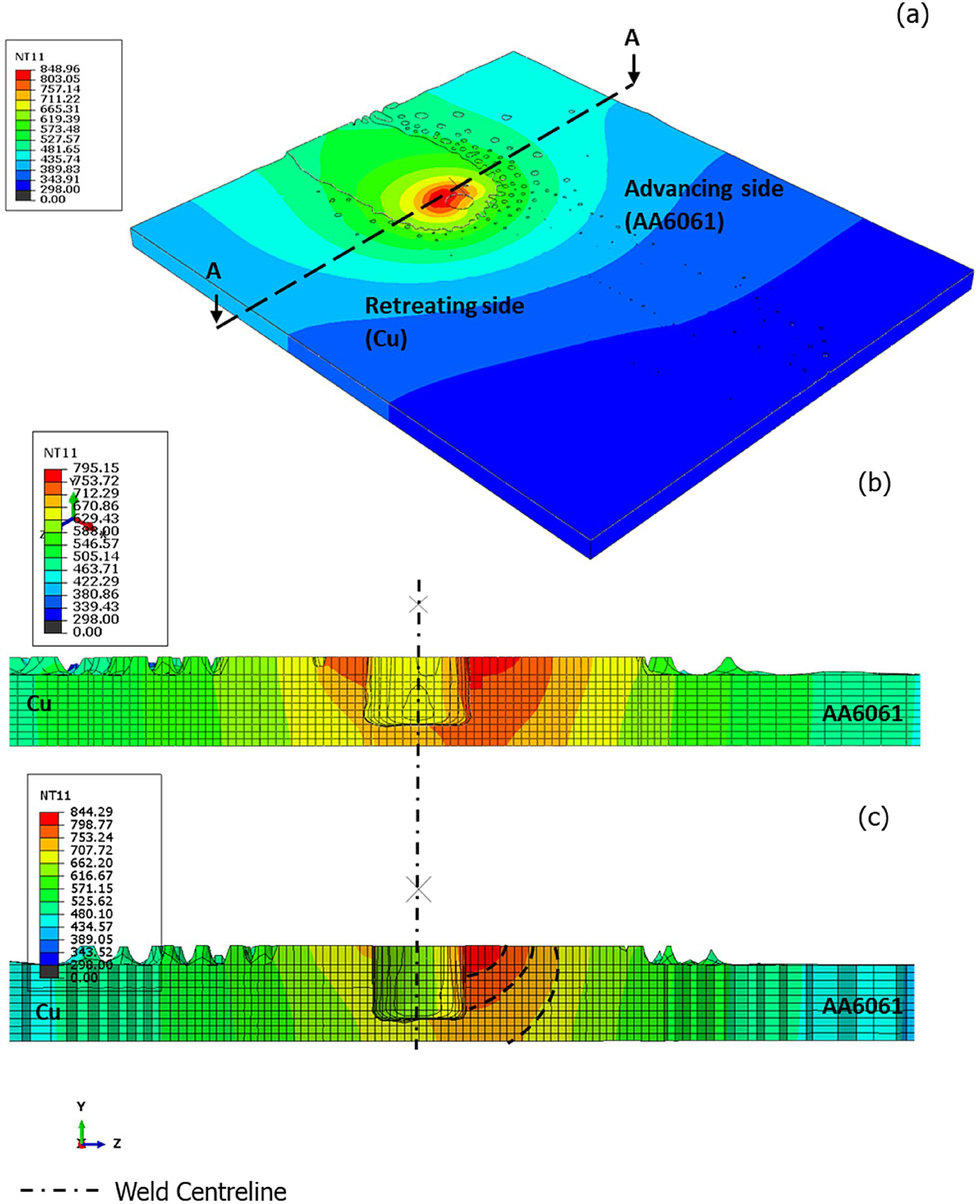
As observed, the calculated temperature within the weldment zone is affected by the tool rotational speed, where increasing the rotational speed increases the heat input and thus the temperature.
Weld quality in the AA6061–copper interface region
The weld quality of the AA6061–copper joint can be generally assessed when its cross-sectional macro features and microstructures are examined from the corresponding optical images. Figure 9(a) shows a macrograph of the dissimilar materials joint of test no. 1 at 1300 rev min−1 rotational speed and 100 mm min−1 welding speed. Figure 9(b,c) shows optical micrographs of the weldment at the interface region and the weld nugget, respectively. Close examination of Figure 9(c) reveals a degree of void formation at the weld nugget which is related to the irregular distribution of copper particles. Inadequate material flow, due to a suboptimal ω/ν ratio, is the main reason for the resultant voids [1].
(a) Typical cross-section of joint welded at 1300 rev min−1 and 100 mm min−1. (b) Interface zone towards AA6061 side. (c) Weld nugget.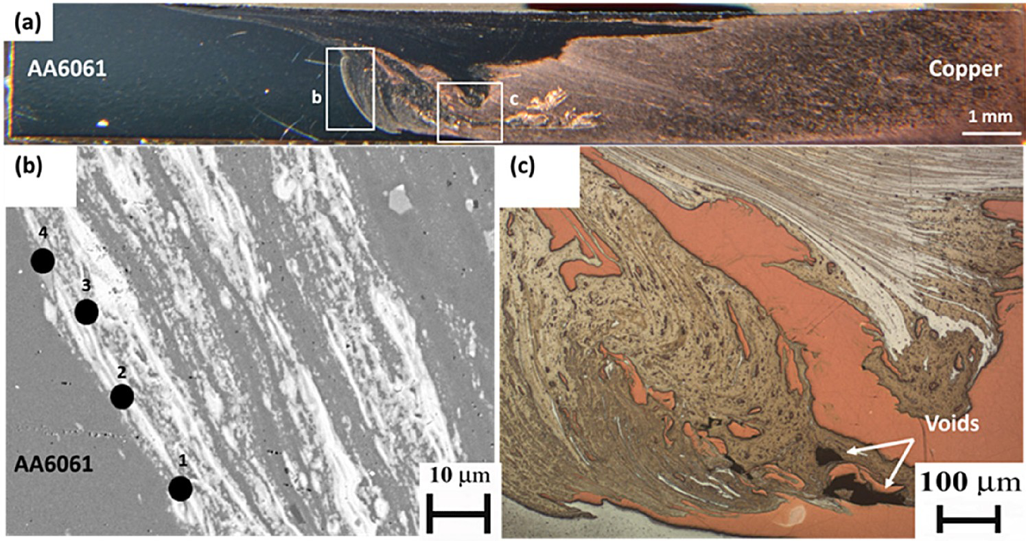
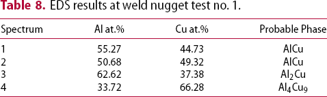
EDS results at weld nugget test no. 1.
Defect-free joints were obtained at the higher rotational speeds of 1400 and 1500 rev min−1 (test nos. 2 and 3). Distinctive regions were observed across the weld joint. Towards the aluminium side (Figure 10(a,b)), relatively large copper particles were identified; these were irregularly distributed between the aluminium interface zone and the upper weld nugget surface. At the bottom of the aluminium interface zone, copper particles (fragments) were stretched and regularly distributed along the stir zone (SZ), as shown in Figure 10(c). Evidence of the intermixing between aluminium and copper particles was also observed at the weld nugget and towards the copper side (Figure 10(d)). Unlike other researchers [6, 7], placing the softer material (AA6061) on the AS with 0 mm tool offset resulted in defect-free joints when a suitable ω/ν ratio was selected.
(a) Typical cross-section of joint welded at 1400 rev min−1 and 100 mm min−1. (b) Interface zone towards AA6061 side. (c) Weld nugget. (d) Interface zone towards copper side. (e) EDS points of rectangle e. (f) EDS points of rectangle f.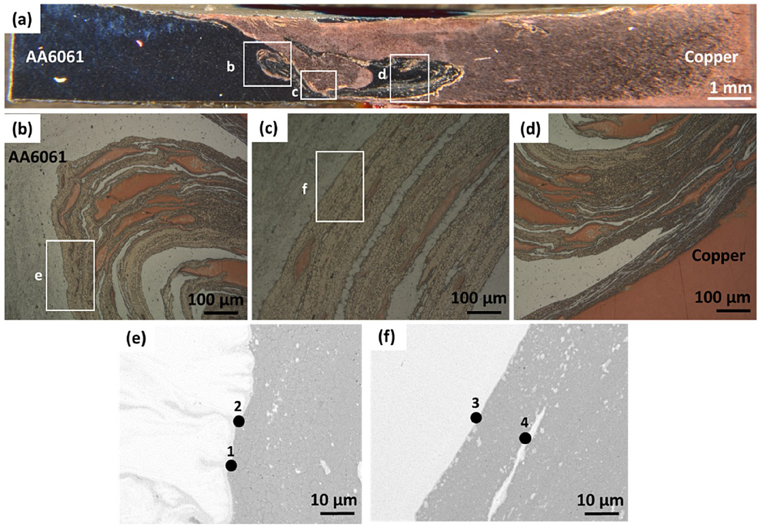
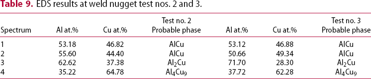
EDS results at weld nugget test nos. 2 and 3.
Comparatively small copper particles were detected as regularly distributed along the aluminium interfacial zone (Figure 11(a–c)) of test no. 3. Sufficient heat input generated by the relatively higher rotational speed of 1500 rev min−1 is the reason behind this enhanced thermo-mechanical effect and the regular dispersion of copper particles in the aluminium. Towards the copper side, refined aluminium grains were intermixed with the copper particles, thus resulting in a wider copper thermo-mechanical affected zone (TMAZ) (Figure 11(d)).
(a) Typical cross-section of a joint welded at 1500 rev min−1 and 100 mm min−1. (b) Interface zone towards the AA6061 side. (c) Weld nugget. (d) Interface zone towards the copper side. (e) EDS points of rectangle e.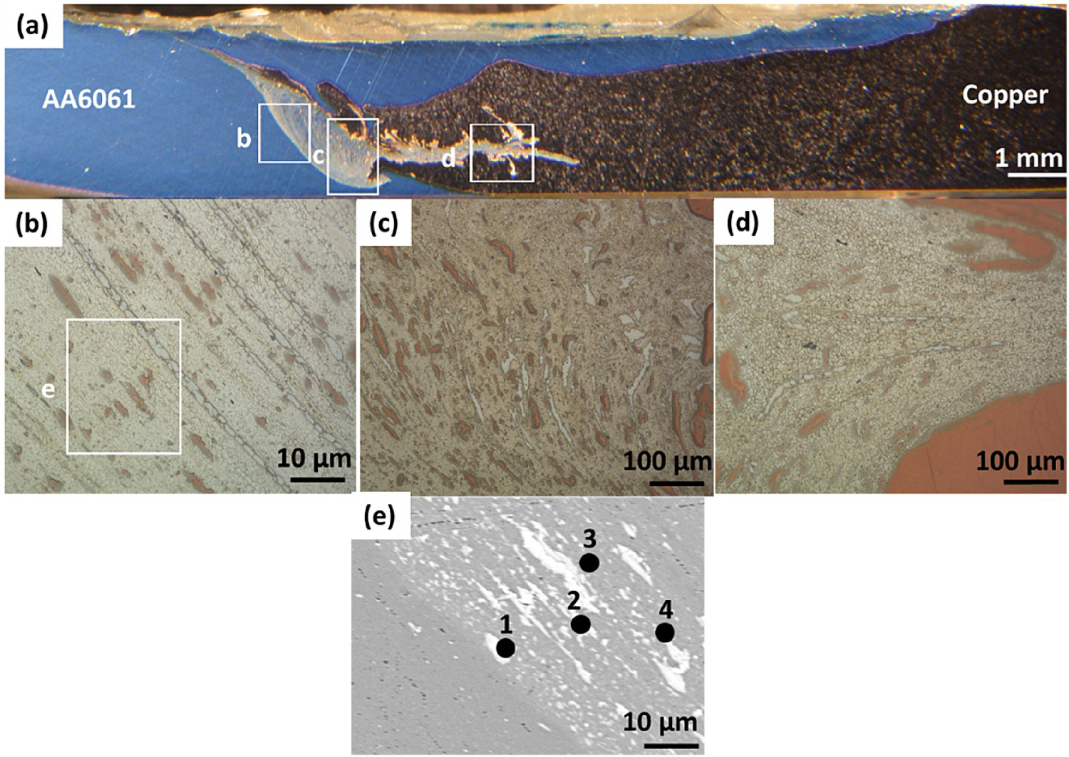
According to the results of Table 9, points 1 and 2 in Figure 11(e), the AlCu IMC phase is identified close to the aluminium side. Al2Cu and Al4Cu9 are the possible phases as per Figure 11(e) points 3–4, and Table 6. This is in agreement with the calculations presented in Section ‘Thermal model validation’ and supports the findings of test no. 2.
Intermetallic phases at the weld nugget zone
For phase identification, XRD analysis was conducted across the weld nugget on defect-free joints of tests 2 and 3 (Table 6). The extracted XRD patterns (Figure 12) revealed that the dominant IMCs in the weld zone of pure copper to AA6061 were AlCu, Al2Cu and Al4Cu9; this is in agreement with the EDS analysis and predictions discussed previously. However, the Al-Cu phase diagram cannot be solely used to reliably predict the formation of IMCs. Based on the temperatures estimated using finite element analysis (FEA) during FSW of copper to AA6061, it was found to be in the range of 80–90% of AA6061 melting point. This temperature range is beyond the formation temperature of AlCu and Al2Cu phases, and lower than the one needed to form Al4Cu9 (1030°C). Despite the low peak temperature during FSW, Al4Cu9 formation is related to the process's thermo-mechanical effect as reported in previous publications [4, 16].
XRD patterns acquired under tests nos. 2 and 3.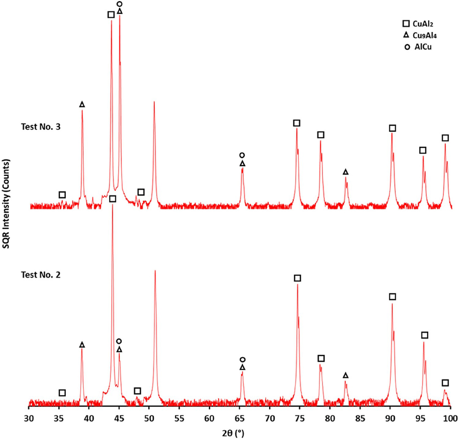
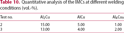
Quantitative analysis of the IMCs at different welding conditions (vol.-%).
Joint mechanical strength
Figure 13(a,b) presents the microhardness measurement locations across the weld nugget and the distribution profile, respectively. The measurements were taken at the middle of the sheet thickness with a step size measurement of 0.7 mm. As predicted, the hardness within the stir zone (SZ) increases significantly as compared to the base metals. This increase is due to the combined effects of grain refinement, the presence of hard and brittle IMCs [1] and the evolution of copper-rich dispersed particles. Similarly, the TMAZ hardness was found to be higher as compared to the base metals due to the combined effect of IMC formation and grain refinement [2, 24]. The variations in hardness within the SZ are a result of the varied distribution of IMCs in the softer materials (aluminium or copper).
(a) Vickers hardness measurement positions. (b) Vickers hardness variation at tests nos. 2 and 3.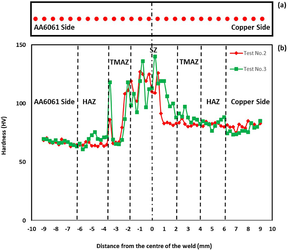
For assessing the impact of tool rotational speed on joint integrity, tensile tests across the weld line of dissimilar joints (AA6061 to copper) generated at the three welding conditions listed in Table 6, were conducted. The results are shown in Figure 14, where the increased tool rotational speed (1300–1500 rev min−1) resulted in a joint strength increase, as well as a higher modulus of elasticity, by 7.0%. This enhancement in mechanical properties is known to be driven by the heat input increase and improved material mixing [1, 2]. Moreover, the joint strength enhancement is directly linked to the distribution, nature, and quantity of IMCs.
Yield strength, Young's modulus, and joint efficiency at the different (ω/v) ratio.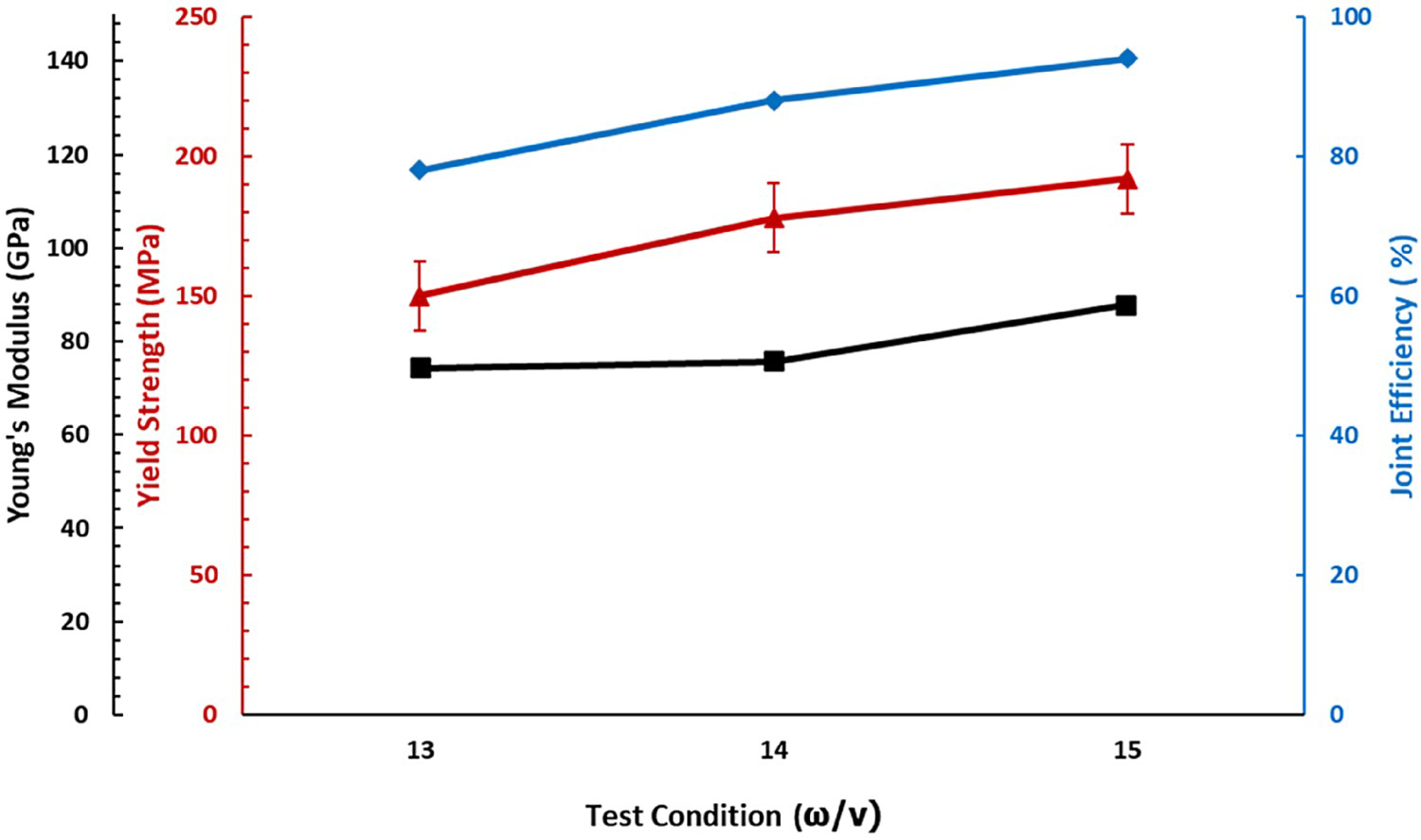
Unlike other published work [5-8] that placed the softer material on the RS, placing the AA6061 on the AS in this work resulted in a higher tensile strength of 194.5 MPa (92.0% joint efficiency). Further, FSWed joints at test no. 3 of higher tensile strength, experienced ductile fracture behaviour with different dimples sizes (Figure 15). All the failures occurred at the TMAZ towards the AA6061 side.
SEM image of the fracture surface at weld test no. 3.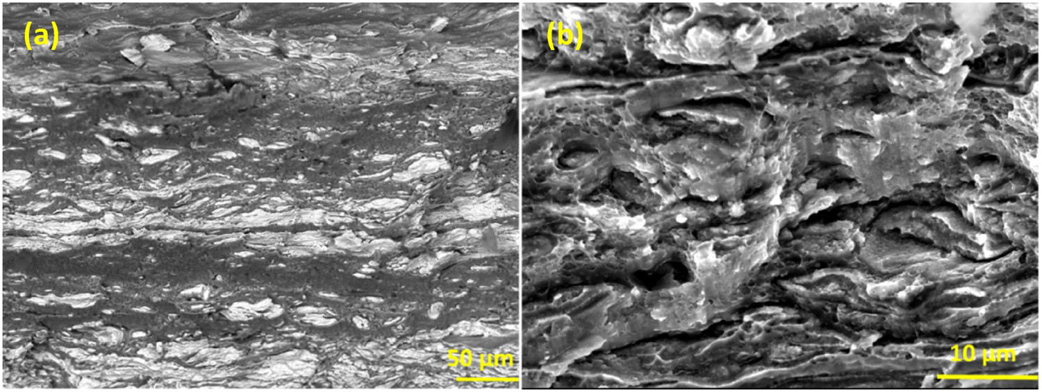
Conclusions
The FSW of AA6061 to commercially pure copper was investigated using experimental and numerical approaches, and the conditions that resulted in defect-free joints were identified. The following conclusions are derived:
The formation of IMCs in FSW of AA6061 to copper has been predicted and validated with the experimental results. The predominant IMC phases in the aluminium–copper dissimilar joint were AlCu, Al2Cu and Al4Cu9. A defect-free weld joint between the two dissimilar materials has been obtained at 1400 rev min−1 and 1500 rotational speeds and 100 mm min−1 traverse speed, where the softer material (AA6061) was placed at the advancing side without any tool offset. Improvements in the UTS were found to be controlled by the relatively regular distribution of IMCs together with the evolution of the composite-like structure.
Footnotes
Disclosure statement
No potential conflict of interest was reported by the author(s).