
Abstract
One thousand two hundred cycles of accelerated exposure experiment with combined salt water spray simulating atmospheric corrosion was performed for investigating the effect of weld line direction and paint orientation on the corrosion and paint deterioration characteristics of welded part of the steel. The corrosion depth of the weld toe of transverse weld line became 1.35 times as large as that of the base metal part because of the remained salt water on the weld toe. The coating thickness at the weld toe became thin by vertically painting on the transverse weld line. When the scribe line was installed at the thin painted weld toe under the transverse weld line, the paint blister area became 15% larger than that of the base metal part. The paint coating thickness at the weld toe in different weld line directions and paint orientations should be confirmed and ensured from the viewpoints of manufacturing and maintaining steel structures.
Introduction
Aging, deterioration and damage of infrastructures have been one of the important issues in the civil engineering field. Maintenance, repair and reinforcement of the damaged infrastructures are required for the long-term use of structures. One of the main causes of the deterioration and damage of steel structures is corrosion. Therefore, anti-corrosion coatings such as painting, galvanising and metal spray are generally applied to the steel members. Painting is the most widely used as anti-corrosion coating for steel bridge members in atmospheric environment.
It is known that the performance of paint coating is strongly affected by the geometric shape of member. The thickness of paint coating tends to be thin on bolted joints with complicated shapes or edge parts of members. As a result, the paint coating is deteriorated earlier around the bolted joints or the edge parts of members than in the generally flat parts [1]. As well as the bolted joints, welded joints used in steel bridges have complicated geometric shapes owing to weld beads. Not only the geometric shape but also other features of welded joints influence the corrosion and the paint deterioration characteristics. For example, galvanic corrosion between base metal and weld metal may occur depending on the difference of chemical compositions of them. Stress corrosion cracking caused by welding residual stress is one of the serious problems related to the welded joints [2].
Although there are a certain number of research works on corrosion of stainless steel welded parts [3 -5], few research works focus on the corrosion of welded parts of structural steel and especially the deterioration characteristics of paint coating of steel welded parts. The corrosion of welded joints decreases the structural performances such as load-carrying capacity and fatigue resistance. Prediction of paint coating deterioration of the steel welded parts in bridges is obviously important because the welded joints are used as the significant connection in bridges. A series of researches were conducted on the corrosion behaviour of non-paint-coated steel and deterioration characteristics of painted steel from scribe defects [6 -9]. However, these researches treated the generally flat base metal part. The influence of welded part on the corrosion and paint deterioration characteristics of steel is not investigated sufficiently.
In this study, a series of accelerated exposure experiment with combined salt water spray simulating atmospheric corrosion [10] was performed on non-paint-coated and paint-coated steel specimens with weld line. In the paint-coated specimens, different painting orientations assuming actual fabrication process of steel structural members were applied on the specimens. Based on the experimental results, the corrosion characteristics of steel with weld line and the paint coating deterioration around the weld line were investigated. Especially, the effects of weld line directions on the corrosion and paint deterioration characteristics were examined.
Corrosion characteristics of steel with weld line
Specimen
Chemical compositions and mechanical properties.
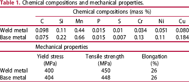
Figure 1 shows the shapes and dimensions of specimens and the setting direction in the chamber. The specimen without weld line, that is, the base metal itself, is named as B specimen. The specimens with longitudinal and transverse weld lines are named as WL and WT specimens, respectively. Here, the longitudinal and transverse directions mean just the direction in the specimen. It should be noted that these directions are not related to the actual weld line directions in the steel structures. The set angle of the specimen was 15° to the vertical direction in the experimental chamber. The number of the specimen was three in each specimen type. Shot blasting (ISO Sa 2.5) was performed on the specimens after welding for removing the scales. The edge parts of the welded side of the specimen were covered by an anti-corrosion tape for keeping non-corroded points used as a reference in calculating the corrosion depth. Another side of the specimen without weld line was also covered by the anti-corrosion tape.
Shapes and dimensions of specimen. (a) Base metal specimen (B), (b) longitudinal weld specimen (WL), (c) transverse weld specimen (WT).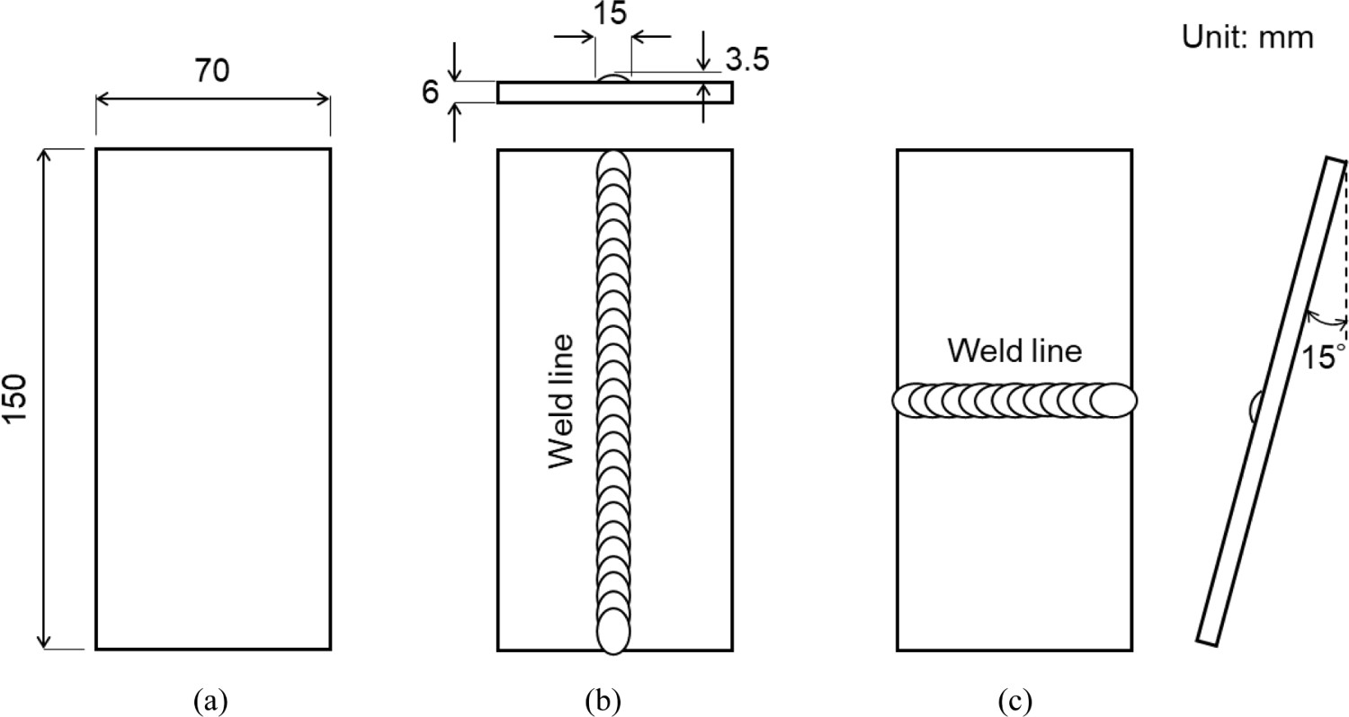
Not only the chemical composition, the geometry of the weld bead and the set position of specimens but also the other factor such as welding residual stress possibly influence the corrosion of welded joints. However, the difference of welding residual stress is not considered in this study because the welding residual stress might be released by cutting the specimen after welding and the surface of all specimens was shot-blasted. The corrosion behaviour of the welded part is basically investigated from the viewpoint of chemical compositions and geometries in this study.
Accelerated exposure experiment
A series of accelerated exposure experiment with combined salt water spray simulating atmospheric corrosion, which is specified in JIS K 5600-7-9 (cycle D) [12], was carried out in this study. Figure 2 shows the conditions of accelerated exposure experiment. At first, 30 min of salt water spray (5% NaCl) is applied under the temperature of 30° C. Ninety minutes of wetting (95% of humidity) is second applied under the temperature of 50° C. And then, 120 min of high-temperature drying (50° C) and 120 min of low-temperature drying (30° C) are applied. It takes 6 h per cycle including salt water spray, wetting and drying with high and low temperature. One thousand and two hundred cycles of the experiment were carried out totally. The locations of specimens in the chamber were changed at every 100 cycles for reducing their influence on the experimental results. The specimens were taken out from the chamber at 400, 800 and 1200 cycles, respectively, for taking photographs of each specimen. The corrosion products were removed by shot blasting with alumina powder. It was confirmed that this blasting material did not change the surface shape of the bare metal but remove the corrosion products on the surface [13]. Then, the surface shape was measured by a laser displacement meter. The measurement pitch in both longitudinal and transverse directions was 0.3 mm. The corrosion depth was calculated by comparing the initial and the corroded surface shapes.
Cycle of accelerated conditions.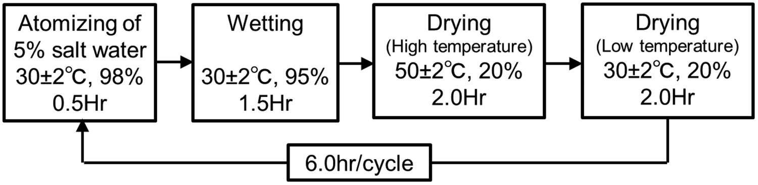
Results of the experiment
Appearance of specimens
Figure 3 shows the appearances of specimens taken out from the chamber at 400, 800 and 1200 cycles. Before and after removing the corrosion products by blasting, local heavy corrosion could not be observed in any part of the specimens.
Appearances of non-painted specimens.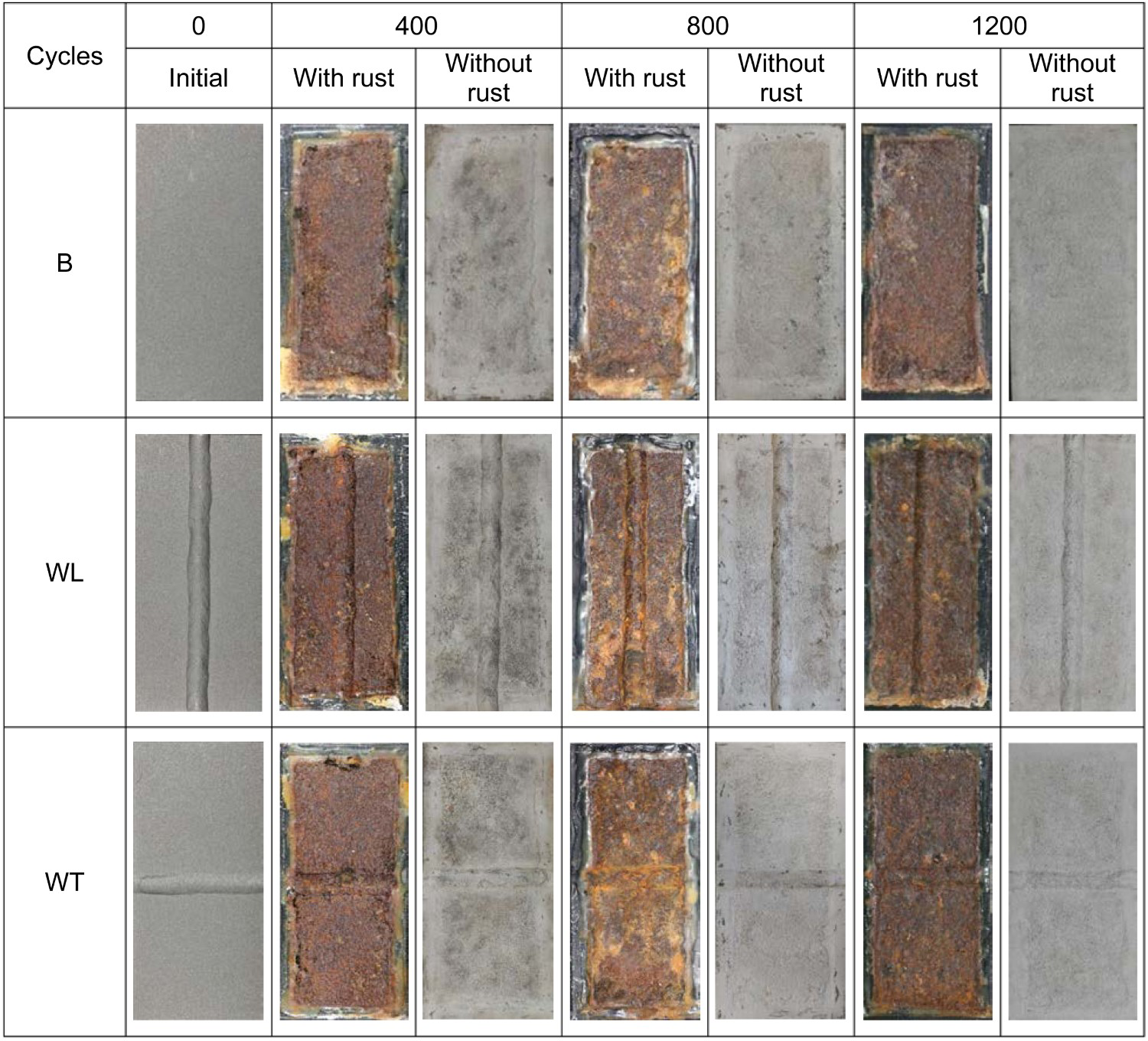
Corrosion depths
Figure 4 shows the surface shape measurement results of WL and WT specimens after 400, 800 and 1200 cycles. The surface shapes in each section were measured. The average surface shape data were assembled from the measurement data in all sections. The dashed line represents the average initial surface shape. The solid line represents the average corroded surface shape. The difference between these lines means the corrosion depth.
Results of surface shape measurement: (a) WL specimen at 400 cycles, (b) WL specimen at 800 cycles (c) WL specimen at 1200 cycles, (d) WT specimen at 400 cycles, (e) WT specimen at 800 cycles, (f) WT specimen at 1200 cycles.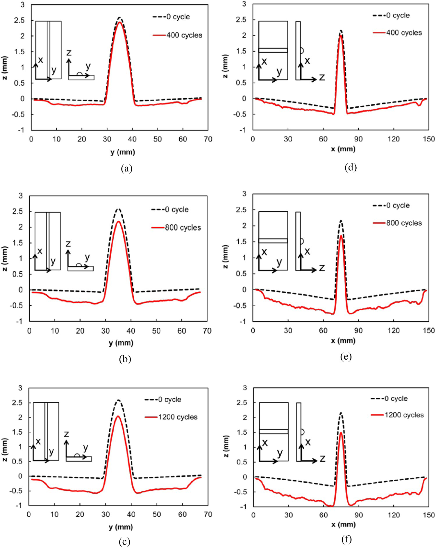
For comparing the corrosion depths in the base metal, the weld toe and the top of the weld bead, the average corrosion depths in the specified regions were separately calculated. Figure 5 shows the region for calculating the average corrosion depth in each part. The corrosion depth of the base metal part was calculated from the region in the base metal away from the weld line. The corrosion depths of the weld toe and the top of weld bead were calculated from the regions with a width of 1 mm including the weld toe and the top of the weld bead, respectively.
Region for corrosion depth measurement.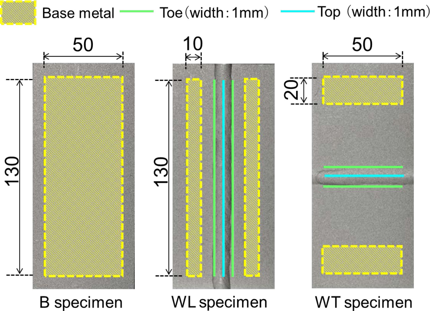
Figure 6 shows the corrosion depths of the base metal, the weld toe and the top of the weld bead at 400, 800 and 1200 cycles. The average (M) and standard deviation (S) calculated from the measurement results of three specimens are shown in the figure. The regression curves of each specimen are also described in the figures. The corrosion depths of B specimens and those of the base metal parts in WL and WT specimens were almost the same. The corrosion depth of the weld toe part in WL specimens was almost the same as that of the base metal part. The corrosion depth of the top of the bead was 1.26 times as large as that of the base metal part at 1200 cycles. On the other hand, the corrosion depth of the top of the bead part was almost the same as that of the weld toe part in WT specimens. They were 1.35 times as large as that of the base metal part at 1200 cycles.
Corrosion depth of WL and WT specimens: (a) WL specimen, (b) WT specimen.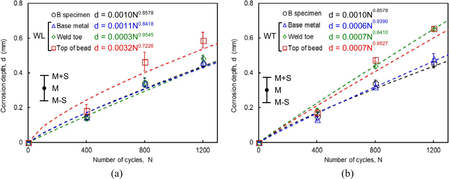
The weld metal used in the specimen contained more carbon and sulfur as shown in Table 1, which may reduce the corrosion resistance, compared with the base metal. Furthermore, the amounts of chromium, nickel and copper in the weld metal, which may enhance the corrosion resistance, were fewer than those in the base metal. From the viewpoint of chemical compositions, the corrosion resistance of the weld metal was lower than that of the base metal. Therefore, the corrosion depth of the top of the bead was larger than that of the base metal regardless of the weld line direction. On the other hand, the corrosion of the weld toe was affected by the weld line direction. When the weld line was set in the horizontal direction in the experimental chamber, sprayed salt water might tend to remain on the weld toe. Therefore, the corrosion depth of weld toe part in WT specimen possibly became larger than that of the base metal part.
The load-carrying capacity of welded joints is generally influenced by the thickness of base metal and the weld toe rather than the weld bead. Not only the static load-carrying capacity but also the fatigue strength is also influenced by the thickness of the weld toe. Furthermore, the thickness of the welded part is basically larger than the base metal part owing to the weld reinforcement. From the viewpoint of the structural performance of welded joints, the corrosion of weld toe should be carefully noted rather than the top of the weld bead.
By the way, the results obtained by this experiment in which the specimens were placed by 15° in the chamber may not be applied directly to vertical or horizontal weld lines in actual steel structural members. However, the experimental results indicated the influence of weld line direction on the corrosion depth of weld toe. The application of tendency of these experimental results to the actual steel member should be investigated continuously.
Paint coating deterioration characteristics around weld line
Specimen
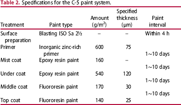
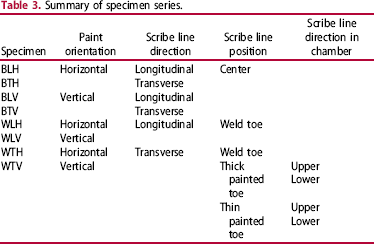
The specimens used in this experiment were the same steel as those used in the previous chapter. B, WL and WT specimens with painting were prepared for investigating the paint coating deterioration characteristics around the weld line. After blasting on the surface of specimens, the paint coating specified as C-5 was applied. Table 2 shows the contents of the C-5 paint system [14]. In order to investigate the effect of paint orientation on the coating thickness, the painting was sprayed by setting the specimens horizontally or vertically as shown in Figure 7. Indexes of ‘H’ and ‘V’ are used for representing the paint orientations in the specimen name. That is, the horizontally and vertically painted B specimens are named as BH and BV specimens as shown in Table 3. In the same way, the horizontally and vertically painted WL and WT specimens are named WLH, WLV, WTH and WTV specimens respectively.
Paint orientations: (a) Horizontal painting, (b) vertical painting. Specifications for the C-5 paint system. Summary of specimen series.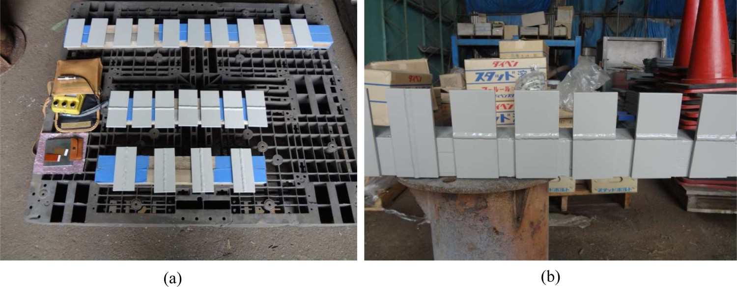
Paint coating thickness
After painting, the coating thicknesses were measured by cutting the specimens and observing the section. Figure 8 shows the photographs of sections and the average of measured paint coating thickness. The number of section measured was 5 in the base metal, the top of the bead and the weld toe parts respectively. The values in the bracket represent the standard deviations.
Measured paint coating thicknesses of each part (μm).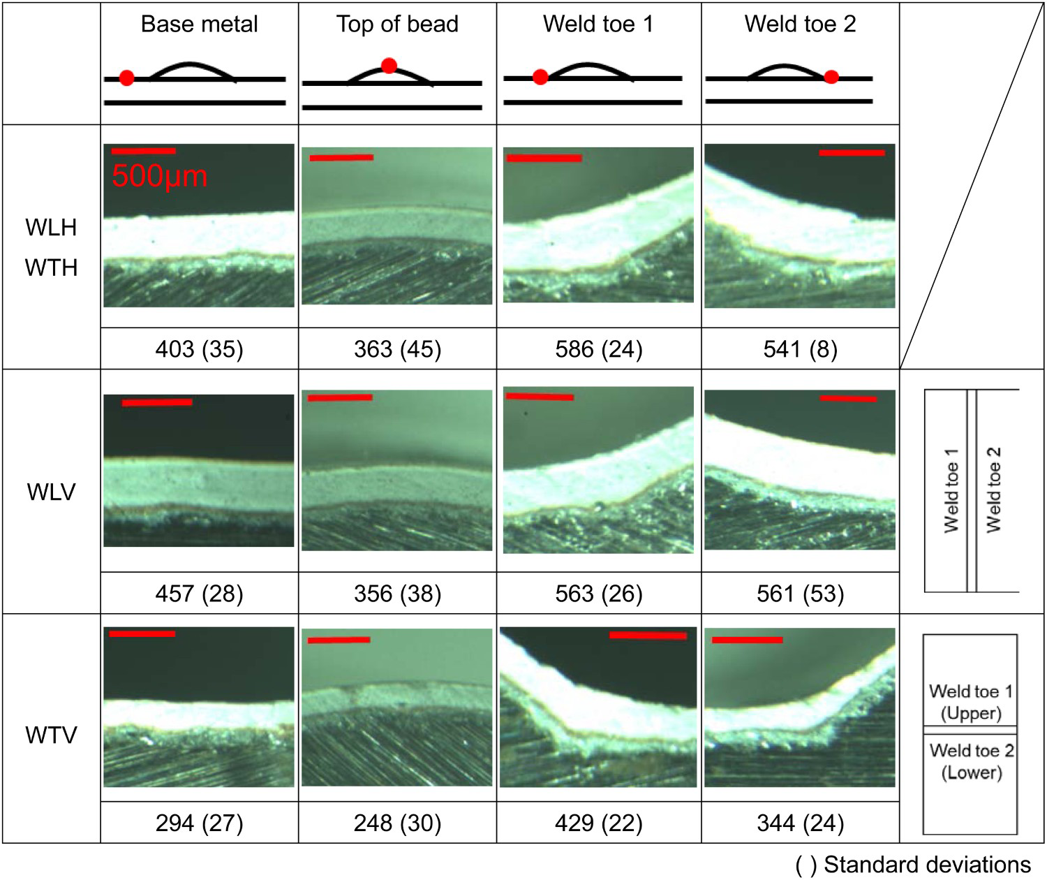
The coating thickness of the top of the bead in WTV specimens was slightly thinner than 250 μm, which is the minimum target thickness specified by the C-5 paint system. In other paint conditions for both WL and WT specimens, the coating thicknesses were over 250 μm regardless of the paint orientations. The coating thickness at top of bead tended to be thinner than those of other parts. On the other hand, the coating thickness at weld toe tended to be thicker than those of other parts. On the whole, the coating thicknesses of all parts of WTV specimens were smaller than those of WLH, WTH and WLV specimens. The reasons for this tendency might be that the liquid paint flew from the top of the bead and collected at the weld toe part owing to the concave welding deformation. Although this estimation should be verified, the coating thicknesses of the lower and upper weld toe of WTV specimens were 61% and 76% of the average coating thickness of weld toe of WLH, WTH and WLV specimens, respectively.
Installation of initial paint defects
Initial paint defects as a scribe straight line was applied on the specimens for the starting point of corrosion in the accelerated exposure experiment. The width of the scribe line was 2 mm. The scribe lines were made to be reached to the substrate steel. The positions of the scribe line are shown in Figure 9. The series of specimens are summarised in Table 3. The number of the specimen in all series was three.
Positions of scribe line: (a) BLH, BLV, (b) BTH, BTV, (c) WLH, WLV, (d) WTV with upper scribe line, (e) WTV with lower scribe line.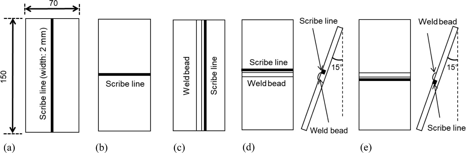
In the case of B specimens, the longitudinal and transverse scribe lines were applied at the centre of the specimen. They are named as BLH, BTH, BLV and BTV specimens. In the cases of WL and WT specimens, the scribe lines were set at the one side of weld toe assuming a paint damage owing to fatigue crack in actual steel structures. It could also be confirmed that the corrosion depth around the weld toe became larger than the top of the weld bead in the experiment of non-painted WT specimens as shown in the previous chapter. The distance from the weld toe to the centre of the scribe line was around 1.4 mm. That position was nearly on the heat-affected zone (HAZ), which is known as corrosion susceptible part around the weld metal [15], observed by macrograph shown in Figure 10. The coating thickness of the upper weld toe was larger than that at the lower weld toe in WTV specimens. Therefore, the scribe lines were set at the thicker and the thinner sides of weld toes, respectively. They are named as the thick or thin painted WTV specimens, respectively. Furthermore, the positions of scribe line made to be upper and lower sides of the weld toe when putting the WT specimens in the chamber (Figure 9(d),(e)). They are named as WTV specimens with upper or lower scribe lines, respectively.
Macrograph and position of HAZ.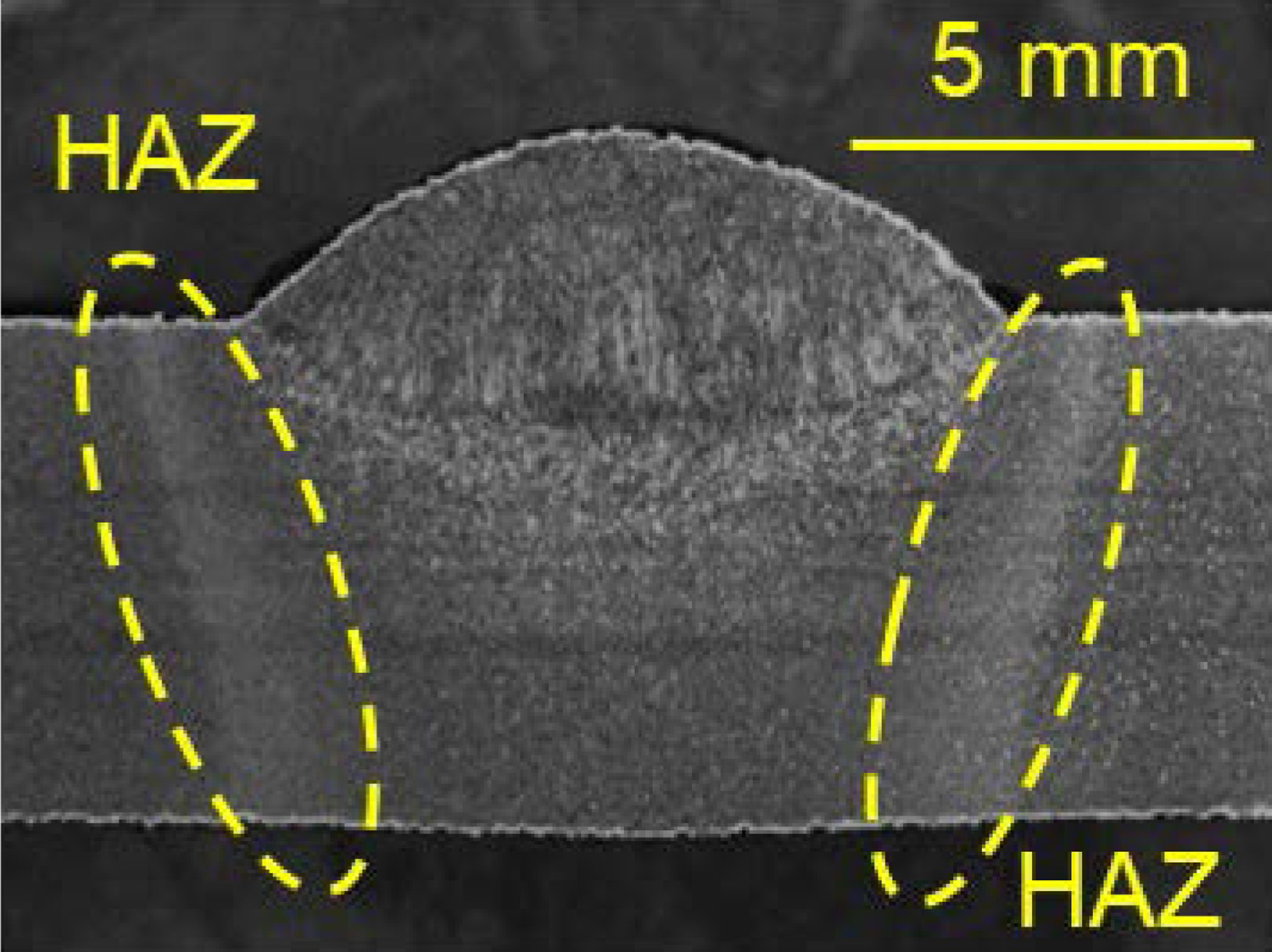
Experimental conditions and evaluation of paint deterioration
The experimental conditions for the painted specimens were the same as the conditions for the non-painted specimens. The same conditions of accelerated exposure experiment shown in the previous chapter were applied on the painted specimens.
An effectiveness of paint blister areas around several types of paint defects has been proposed for evaluating the progress of corrosion of painted steel materials [16]. The paint blister is also used as a measure for corrosion deterioration of steel in this study. The definition of paint blister area is the area in which the paint blister height is over 50 μm from the sound paint region [16]. The sound paint region in B specimen was selected from the part far from the scribe line. In the case of WL and WT specimens, the initial surface shape was subtracted from the surface shape measured at each experimental cycle. The part in which the difference between the initial surface shape and the surface shape with blister was over 50 μm was defined as the paint blister area. The obtained paint blister area was divided by the weld length. The paint blister area per unit weld length was evaluated for comparing WL and WT specimens. The regions for calculating the paint blister area of B, WL and WT specimens were inside the dashed lines shown in Figure 11 for removing the edge parts with local corrosion.
Calculation area for paint blister: (a) BLH, BLV, (b) BTH, BTV, (c) WLH, WLV, (d) WTH, WTV.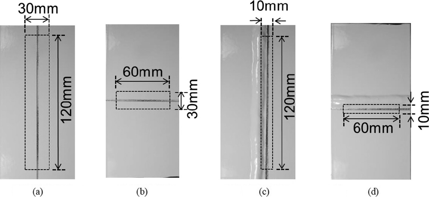
Results of experiment
B specimens
Figure 12(a) and (b) shows the comparison of paint blister area with different paint orientations in B specimens. The difference of paint blister areas of BH and BV specimens was not so large in both the longitudinal and transverse scribe lines. The difference between them was from 4 to 8%. Therefore, the differences of pain orientations in B specimens are not considered for evaluation. Figure 12(c) shows the comparison of the paint blister area with different scribe line directions. The paint blister area of BT specimens was 15% larger than that of BL specimens at 1200 cycles. It might be that water and salt tended to remain around the transverse scribe line easier than that around the longitudinal scribe line.
Paint blister areas of B specimens: (a) comparison between BLH and BLV. (b) Comparison between BTH and BTV. (c) Comparison between longitudinal and transverse scribe lines.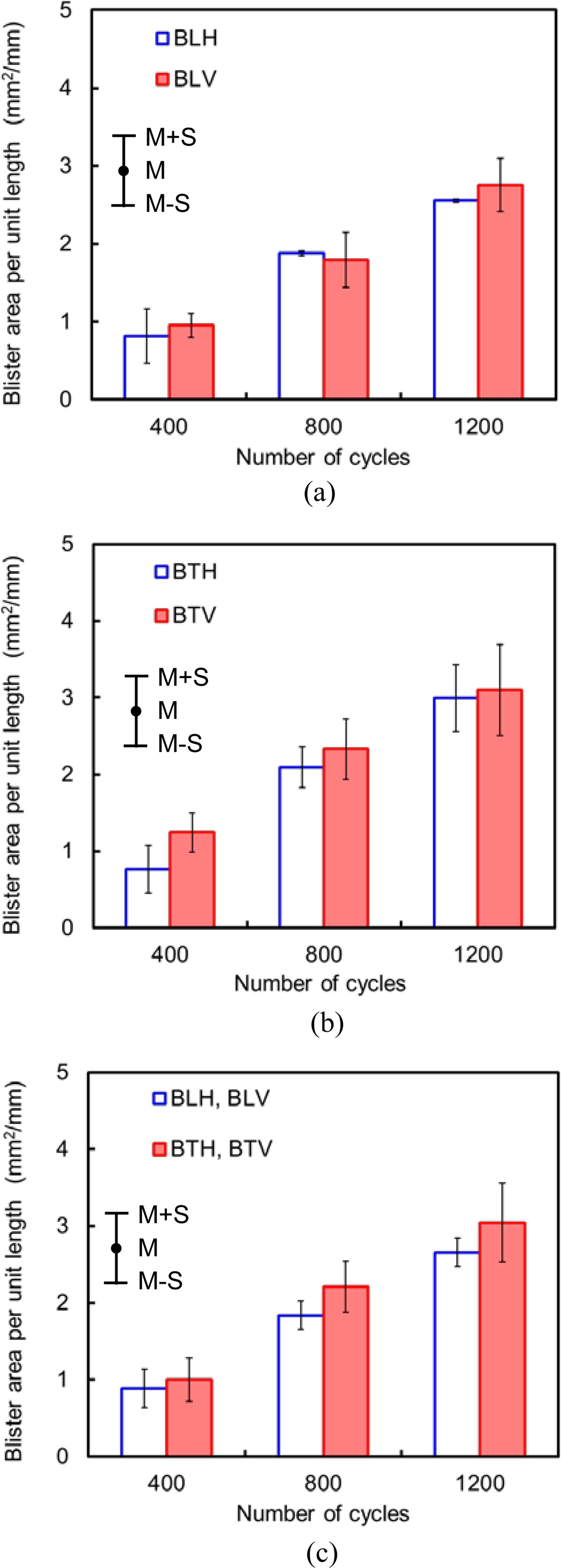
WL specimens
The variation of data is relatively large in the weld specimens compared with the base metal specimens because the calculation area of paint blister includes the weld bead shape which is different in each specimen. Although it is difficult to quantitatively evaluate the paint blister including the dispersion, the tendency of paint blister progress is discussed.
Figure 13 shows the increase of paint blister area of WL specimens. The difference of paint blister area between WLH and WLV specimens was within 10%. The coating thickness at the weld toe was not affected by the paint orientation of WL specimens. Therefore, the paint blister area of WLH and WLV specimens might be almost the same.
Paint blister areas of WL specimens.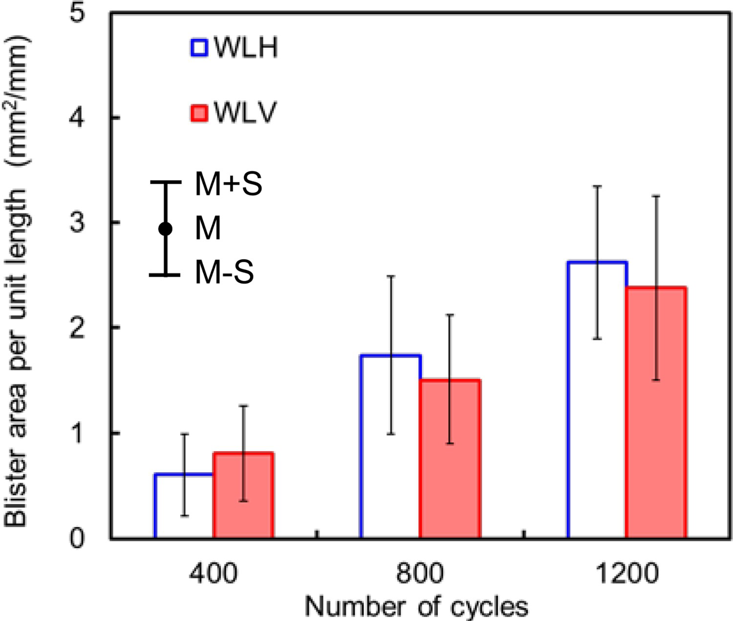
WT specimens
The coating thicknesses at weld toes of WTH and WTV specimens were largely different as shown in Figure 8. Therefore, the paint blister area was evaluated by each paint orientation first. Figure 14(a) shows the increase of paint blister area of WTH specimens. When comparing WTH specimens with upper and lower scribe lines, the paint blister area of WTH specimen with lower scribe line was 8% larger than that with upper scribe line at 1200 cycles. Figure 14(b) shows the comparison between thick and thin painted WTV specimens. The paint blister area of WTV specimen with lower scribe line was larger than that with upper scribe line in both the thick and thin painted cases. This tendency is the same as WTH specimen. It was natural that the paint blister area of thin painted WTV specimen was larger than that of the thick painted WTV specimen. In the case of the WTV specimen with lower scribe line, the paint blister areas of the thin painted WTV specimen at 1200 cycles was 27% larger than that of the thick painted WTV specimen.
Paint blister areas of WT specimens: (a) WTH specimens, (b) WTV specimens.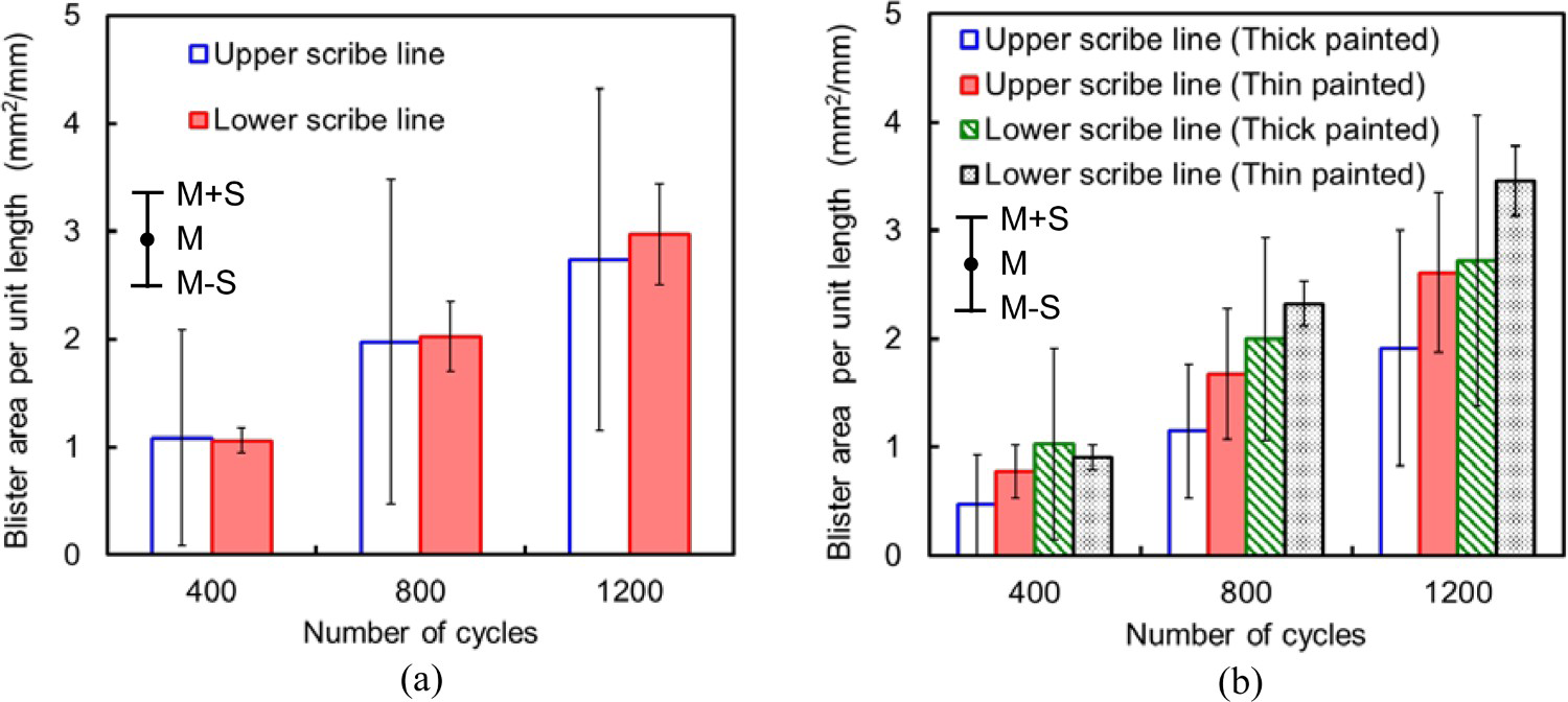
Influence of weld line direction and difference between base metal and weld metal
In order to compare the paint blister areas of WL and WT specimens, WLH and WTH specimens with the same conditions except for only the weld line direction are noted. Figure 15 shows the paint blister areas of WLH and WTH specimens at 1200 cycles. The average paint blister area of WTH specimen with upper and lower scribe lines are shown in this figure because the influence of scribe line position was small in these specimens. The paint blister areas of BLH and BTH specimens are also shown in the figure. Although the paint coating thicknesses of them were almost the same, the paint blister area of WTH specimen 9% larger than that of WLH specimen. More water and salt possibly tended to remain around the weld toe of WTH specimen than that of WLH specimen. It might be that the paint coating of WTH specimen deteriorated earlier than that of WLH specimen as well as the comparison of BLH and BTH specimens. However, the paint blister areas of WLH and BLH specimens were almost the same. These of WTH and BTH specimens were also the same. When the specified coating thicknesses at the weld toes are ensured as well as the base metal part by horizontal painting, the degree of paint coating deterioration at the weld toe is possibly the same as that at the base metal.
Paint blister areas of WLH, WTH, BLH and BTH specimens.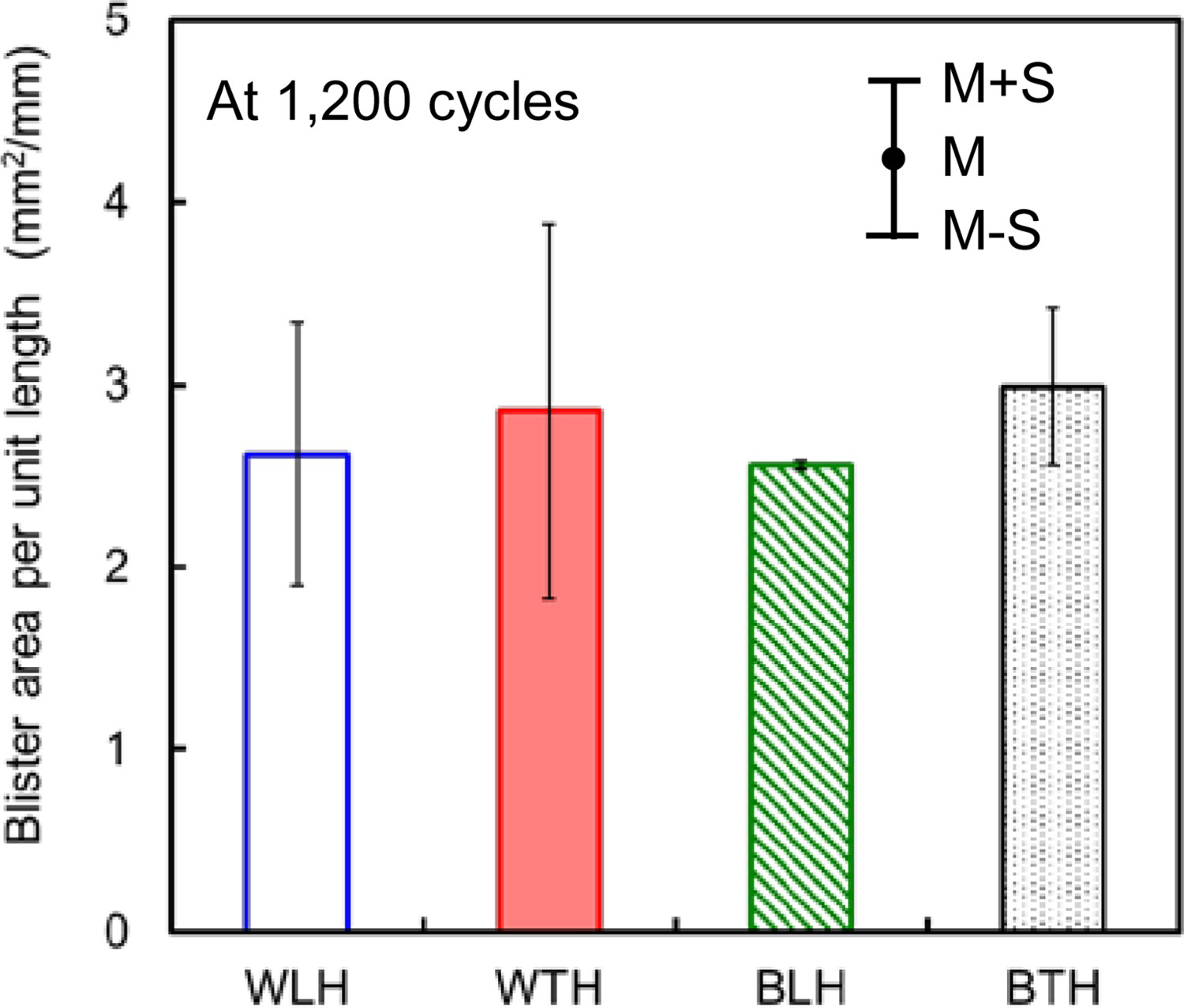
Figure 16 shows the paint blister areas of BTV and WTV specimens at 1200 cycles. In the case of WTV specimens, the paint coating thickness at the upper weld toe was larger than that at the lower weld toe. The paint blister area of thin painted WTV specimen with lower scribe line was 15% larger than that of BTV specimen. On the other hand, the paint blister areas of the other WTV specimens were smaller than that of the BTV specimen. Based on the experimental results in this study, the paint coating at the weld toe deteriorated earlier than that at the base metal part in specified conditions such as the weld line directions and the paint orientations. The most severe condition for the paint coating at the weld toe was the case that the coating thickness at the weld toe became thin by vertically painting on the transverse weld line and the scribe line at the thin painted weld toe was set the lower side by arranging the specimens in the chamber. From the viewpoints of manufacturing and maintaining steel structures, it is important that the paint coating thickness at the weld toe is confirmed and ensured for the different weld line directions and the paint orientations.
Paint blister areas of WTV and BTV specimens.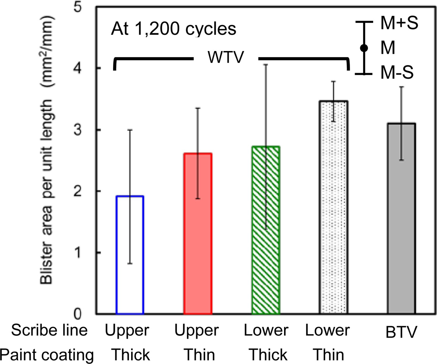
Conclusions
A series of accelerated exposure experiment with combined salt water spray was performed for investigating the corrosion characteristics of steel with weld line and the paint coating deterioration around the weld line in different directions. Obtained main results are as follows:
The weld metal used in the specimen contained more C and Compared with the base metal. The amounts of Cr, Ni and Cu in the weld metal were fewer than those in the base metal. From the viewpoint of chemical compositions, the corrosion resistance of the weld metal was lower than that of the base metal. Therefore, the corrosion depth of the top of the bead part was larger than that of the base metal part regardless of the weld line direction. Based on the accelerated exposure experiment performed in this study, the corrosion depth of the top of the bead part was 1.26 times as large as that of the base metal part at 1200 cycles. The corrosion of the weld toe was affected by the weld line direction. When the weld line was set in the horizontal direction, sprayed salt water might tend to remain on the weld toe. Therefore, the corrosion depth of the weld toe part possibly became larger than that of the base metal part. Based on the accelerated exposure experiment performed in this study, the corrosion depth of the weld toe part in the transverse weld line was 1.35 times as large as that of the base metal part at 1200 cycles. However, the corrosion depth of the weld toe part in the longitudinal weld line was almost the same as that of the base metal part. It could be confirmed that the paint coating thickness at the weld toe was largely affected by the paint orientations. The coating thickness at the top of bead tended to be thinner, while the coating thickness at the weld toe tended to be thicker than those of base metal parts. The reasons for this tendency might be that the liquid paint flew from the top of the bead and collected at the weld toe part owing to the concave welding deformation. When vertically painting on the transverse weld line, the coating thickness at the upper and lower weld toes were 61% and 76% of those of horizontally painting or vertically painting on the longitudinal weld line. The paint coating at the weld toe of transverse weld line deteriorated earlier than that of longitudinal weld line because more water and salt possibly tended to remain around the weld toe of transverse weld line than that of longitudinal weld line. Although the paint coating thicknesses of them were almost the same, the paint blister area of the transverse weld line was 9% larger than that of the longitudinal weld line at 1200 cycles of the accelerated exposure experiment. The paint coating at the weld toe deteriorated earlier than that at the base metal part in specified conditions such as the weld line directions and the paint orientations. The most severe condition for the paint coating at weld toe was the case that the coating thickness at weld toe became thin by vertically painting on the transverse weld line and the scribe line at the thin painted weld toe was set the lower side by arranging the specimens in the chamber. The paint blister area of the thin painted transverse weld line, of which the scribe line was installed on the lower side of weld toe, was 15% larger than that of the base metal part. There are many factors affecting the paint blister area around the weld toe. It was difficult to identify the dominant factor deciding the paint deterioration among the experimental conditions in this study. At least, the weld line direction and the paint orientation affected the paint coating thickness at the weld toe. When the paint coating thickness became thin under the specified condition and the scribe line was installed there, the paint blister possibly became larger than that of the flat base metal part. Therefore, the main factor in this study is the paint coating thickness. However, the quantitative relationship between the coating thickness and the blister area is still unknown and it will be the future work. In any case, it is important that the paint coating thickness at the weld toe is confirmed and ensured for the different weld line directions and the paint orientations from the viewpoints of manufacturing and maintaining steel structures.
Footnotes
Disclosure statement
No potential conflict of interest was reported by the authors.