






Abstract
The present work aims at determining the critical material properties that can be used to tailor the crush behaviour of pultruded GFRP (Glass Fibre Reinforced Polymer) box-beams, as can be found in, for example, roadside furniture such as guard-rails. For this purpose, the mechanical behaviour and energy absorption mechanisms of the constituent pultruded box-beam sections subjected to lateral compressive loading, the dominating load case in composite structures when used as roadside furniture, have been studied. The analysed pultruded profiles consist of E-glass fibre reinforcements with two different lay-up configurations in a polyester matrix. The lateral crushing of profile sections is experimentally evaluated and further numerically studied using commercially available tools, applying readily available models incorporated in the software, in analogy to common practice in designing structures, to identify design and material parameters for improving the fracture behaviour of pultruded GFRP profiles. From the analyses, it is shown that the junctions between flanges and webs are the weakest points of box-beam sections: here, high shear stress concentrations in combination with occurring matrix failure lead to further damage such as delamination and tearing. This behaviour is well-described using the Hashin damage model within ABAQUS. Predicted failure behaviour corresponds with observed experimental results, whereas the material stiffness is underestimated. It is shown that the out-of-plane properties (transverse tensile and shear strength) are the dominant parameters affecting the overall performance.
Introduction
In the past years, a widening range of passively safe roadside furniture made of composites was coming to the market. Composite materials provide lightweight structures with high strength, impact and fatigue resistance in combination with improved corrosion resistance and a long maintenance-free life. Mainly pultruded profiles are used since pultrusion is one of the fastest and most cost-effective manufacturing processes to produce composites. Conventional pultruded fibre-reinforced plastic profiles are typically manufactured in profile shapes that mimic metallic versions to replace steel, aluminium and reinforced concrete for example building frames and bridge decks. 1 Pultruded plates or profiles are relatively thick structural composite components, made of different reinforcing combinations of rovings and fabrics such as filament mats, woven or non-crimp fabrics through the thickness. Continuous longitudinally running rovings provide the main load-bearing component. Moreover, multidirectional continuous strand mats or non-crimp fabrics improve mechanical properties, e.g. the transverse strength. Besides structural reinforcement, an outer mat layer or surface veil is typically used to provide smooth outer profile surfaces 2 and acts as a corrosion barrier that prevents the protrusion of reinforcing fibres to the surface allowing corrosive media into the laminate. Pultruded composites, if compared with composites made by resin transfer moulding technique, generally show a higher void content and unevenly distributed reinforcements, especially in transition regions within the cross-sections, e.g. corners of box beams. 3
Numerous experimental studies on various mechanical properties of pultruded composites have been reported in literature. Coupon type specimens taken from pultruded profiles have been tested to develop and calibrate micromechanical model approaches for progressive damage and elastic-degrading analyses.4–9 Several authors reported on the progressive deformation behaviour, buckling and energy absorption capacities under axial loading.1,6,10,11 Bending stiffness and buckling response of pultruded beams, with different lay-up configurations and cross-sectional shapes, subjected to lateral loads are described in detail12–17 as well as the low velocity impact response using a falling weight impact tower.18–23 All reported tests on box-beam sections under axial and lateral loading revealed progressive tearing, the separation of the vertical and horizontal members at the corners of the cross-section.
Besides that, several numerical analyses of pultruded profiles using different developed non-linear material damage models, implemented in two-dimensional FE models, were conducted.1,3,13–17
Pultruded composites are mainly designed to carry axial loads, hence predominantly reinforced in axial direction, lacking particular out-of-plane properties. The main objective of the present paper is to identify critical material parameters that define the crush behaviour of pultruded GFRP box-beams as used in composite structures for roadside furniture, to improve subsequently the fracture toughness of pultruded GFRP profiles and to enhance the ability to absorb energy through materials and manufacturing solutions in order to broaden the field of applications of pultruded profiles with respect to non-axial loading. The overall behaviour of composite structures is commonly analysed with material models readily available in the numerical software used, as to reduce the overall complexity of the model and thus calculation time. In order to be able to extend the findings of the current research to larger-scale composite structures, an efficient methodology is required, using an existing commercial damage modelling tool, for the characterisation of the mechanical performance and the prediction of failure modes in pultruded box-beam profiles subjected to lateral impact.
According to Tabiei et al., 18 a quasi-static test can be used as an indicator of the relative impact performance of pultruded box beams for low-velocity impact events. In analogy, in this work, to study the crushing behaviour, occurring failure modes and energy absorption mechanisms, simple quasi-static laboratory compression tests are performed using flat platens at top and bottom for lateral loading, as shown in studies for wet wrapped and braided composite tube sections.24–26
Experimental analysis
Materials
Lay-up details of box-beam profiles

CSM: continuous strand mats; NCF: non-crimp fabric.
Box-beam sections with a width of 15 mm were cut from the selected profiles. For each material configuration, 6 sections were randomly chosen to determine a representative mechanical behaviour under compression loading. The specimens were machined using a water-cooled bench saw and the edges were prepared by grinding to the final dimensions.
Although it is generally assumed that unidirectional rovings exit the pultrusion die at 0° orientation and oriented fabrics exit the die at their given orientations, it is well known that the reinforcing material can ‘wander’ during the pultrusion process. Thus pultruded materials commonly vary in orientation within the same section along the length or through the thickness.
27
In Figure 1, pictures taken from cross-sections of the profiles with exemplary bad fabric orientations for the two different material configurations studied are shown. As exemplified in Figure 1(a) and (b) layer thickness and geometry were found constantly changing along the profiles tested. Thus, the fibre architecture was additionally investigated by optical microscopy and averaged thicknesses estimated, as presented in Table 1. Besides these variations of layer thickness and through-thickness position of both profiles, the specimen preparation revealed visible pre-existing laminate defects in Configuration 1 such as wrinkling of the inner layer and cracks in 45° direction in the profile corners (see Figure 2(a)), as well as partial damages of the inner profile surface as shown in Figure 2(b), whereas Configuration 2 samples presented no visible defects.
Layer deviations in Configuration 1 (a) and 2 (b). Microscopic views of pre-existing defects in Configuration 1 (a) and (b).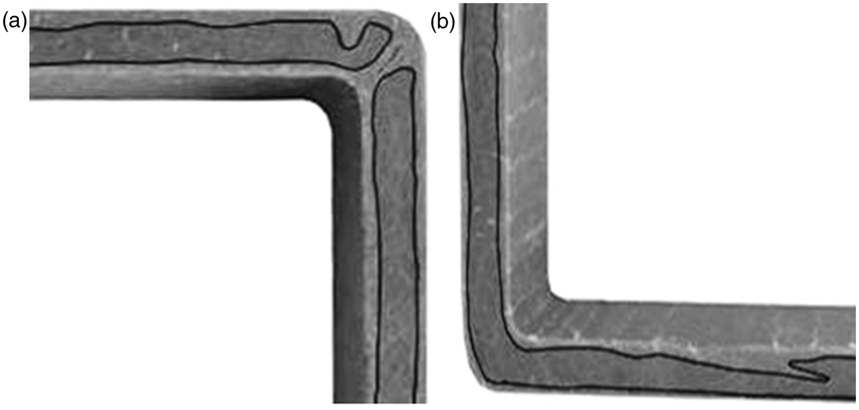

Material properties of composite constituents
Lateral compression experiments
The quasi-static lateral compression tests of the 3D square sections of the pultruded profiles were performed on a 50 kN universal testing machine from Shimadzu. Six sections for each configuration were loaded at a test speed of 5 mm/min until final failure occurred. The load was applied to the specimen through flat, circular, fixed platens as shown in Figure 3, in such a manner that the load was uniformly distributed over the entire loading surface of the specimen. Load-displacement details were taken to determine maximum load, ultimate strength as well as energy absorption capabilities. The compression tests were additionally recorded with a Photron Fastcam APX-RS high-speed camera to provide visual insight into the progressive damage of pultruded profiles.
Test set up for lateral compression tests of the pultruded box-beam sections.
Results and discussion
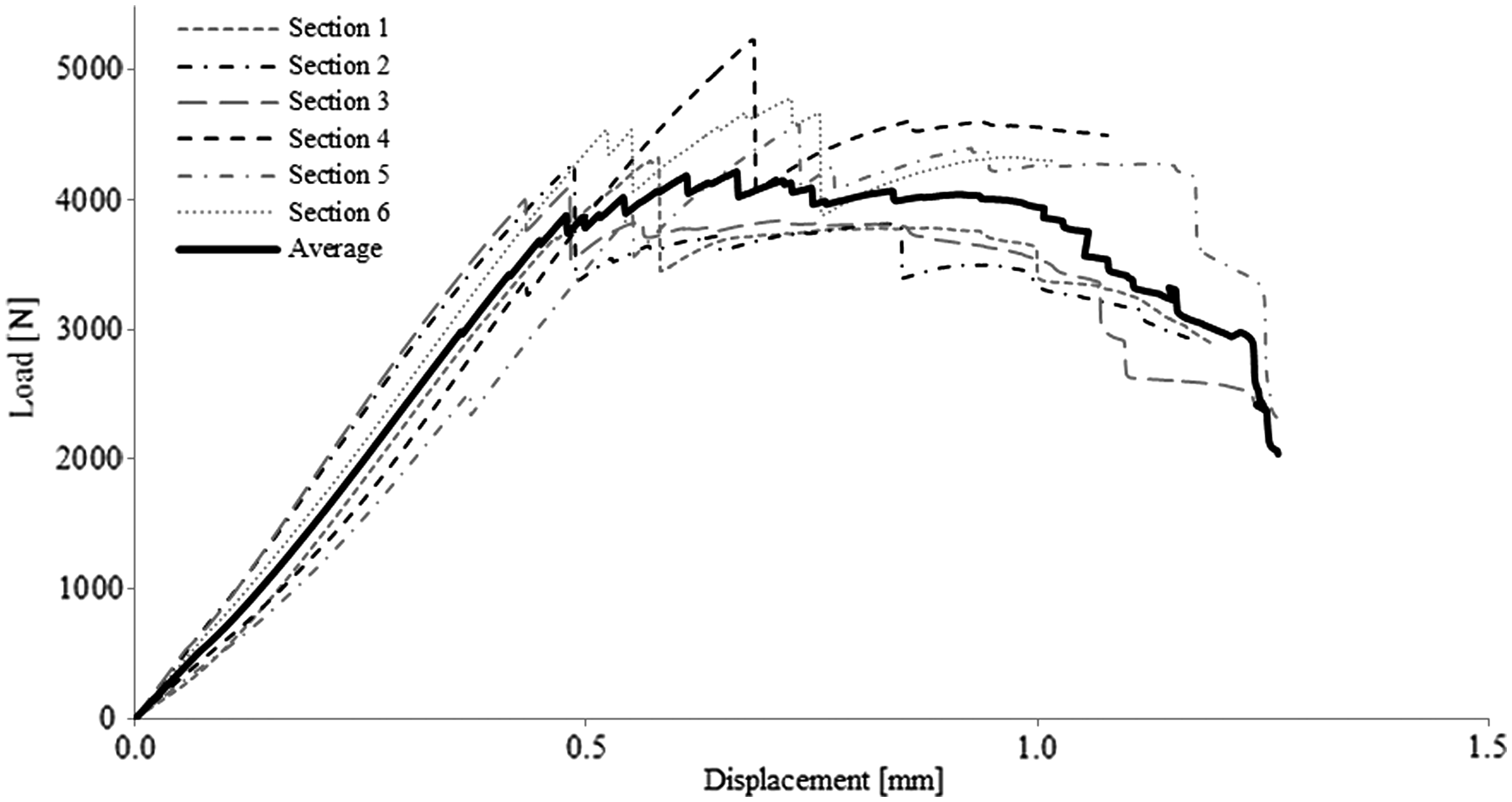
Mechanical behaviour and load responses. Load displacement curves for Configurations 1 and 2 under compressive loading are presented in Figures 4 and 5, respectively. Additionally, averaged graphs were derived by averaging occurring forces in all sections according to each displacement. Figure 6 presents the resulting curves with associated standard deviations. The graphs are used as representative load-displacement curves of both pultruded profiles for further discussion. The differing shapes of the load-displacement curves reveal the diverse material behaviour of the configurations. Sections of Configuration 2, as seen in Figure 5, present a distinct load peak, a continuing load bearing phase as well as a sudden load drop indicating the final fracture. In contrast, the load-displacement curves of Configuration 1, as shown in Figure 4, are characterised by gradual material failure induced by minor fractures in the corners due to pre-existing defects. Both profiles show stiffening-softening-stiffening trends. Unlike Configuration 2, the load-displacement curve of Configuration 1 shows after occurring drops in load more phases of increasing load bearing capacities caused by altering load distributions in the profile section. Transitions from a stiffening phase to a softening phase are marked by sudden material rupture and sound. Furthermore, it is evident that Configuration 1 allows higher vertical deformations, whereas Configuration 2 reaches lower deformations but higher peak loads. Vertical deformation is defined as the displacement at which final fracture arises that impedes further loading of the section or a load reduction bigger than 15% occurs.
Load versus displacement response of Configuration 1 sections. Load versus displacement response of Configuration 2 sections. Representative load versus displacement responses with standard deviations of Configuration 1 and 2.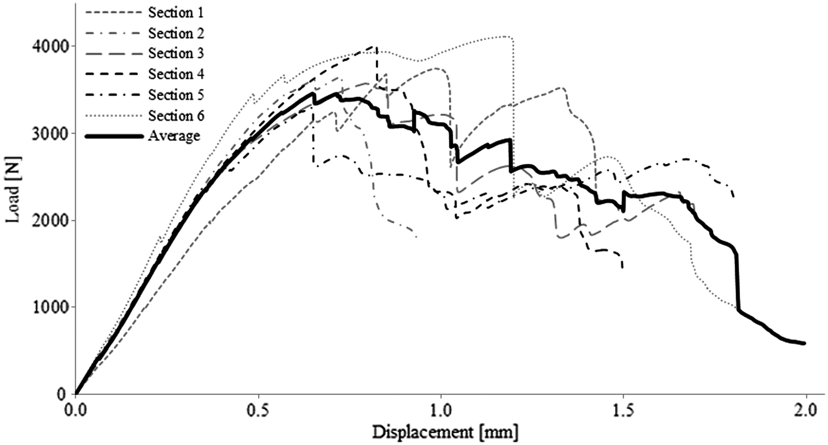

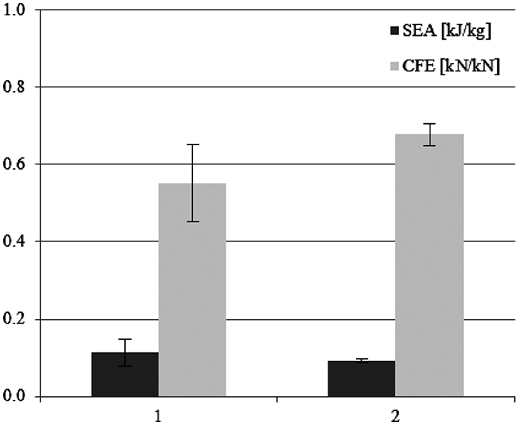
In order to quantitatively compare the tested profiles, following parameters were determined from the test data to assess the structural crush characteristics of each profile. The compressive strength of the profiles was calculated as the ratio of load divided by the total cross-sectional area of the pultruded laminate. The total area under the load-displacement curve represents the total absorbed energy which is defined as the work done by the loading plate, while the peak energy is defined as the amount of absorbed energy until the maximum load is reached. The specific energy absorption (SEA) is defined as the ratio of the total energy absorbed by a structure to its mass. A further parameter to evaluate the mechanical performance of structures during crushing is the crush force efficiency (CFE), the ratio between mean force during crushing and the maximum force.
Results in Figure 7 show that sections of Configuration 2 bear higher peak forces and consequently the ultimate compression strength is higher as well. In general, a stiffer material stores less energy than a more flexible material. The results reveal that sections cut from Configuration 1 present better energy absorption capacities: peak energy and total absorbed failure energy are higher for Configuration 1. This can be explained by the longer lasting load bearing capacities due to a more flexible material behaviour, resulting in a higher overall toughness. Standard deviations for failure energies show that sections of Configuration 1 present stronger varying failure behaviours than sections of Configuration 2 caused by different pre-existing defects and related occurring failure modes. Regarding the SEA, results in Figure 8 show that Configuration 1 presents due to higher total failure energies and lower Vf, thus resulting in a lower density, better energy dissipation capacities. Results for CFE reveal that Configuration 2 is more efficient than Configuration 1 due to a more consistent load-bearing behaviour.
Mechanical properties of Configurations 1 and 2 under compressive loading. Crashworthiness parameters of Configurations 1 and 2 under compressive loading.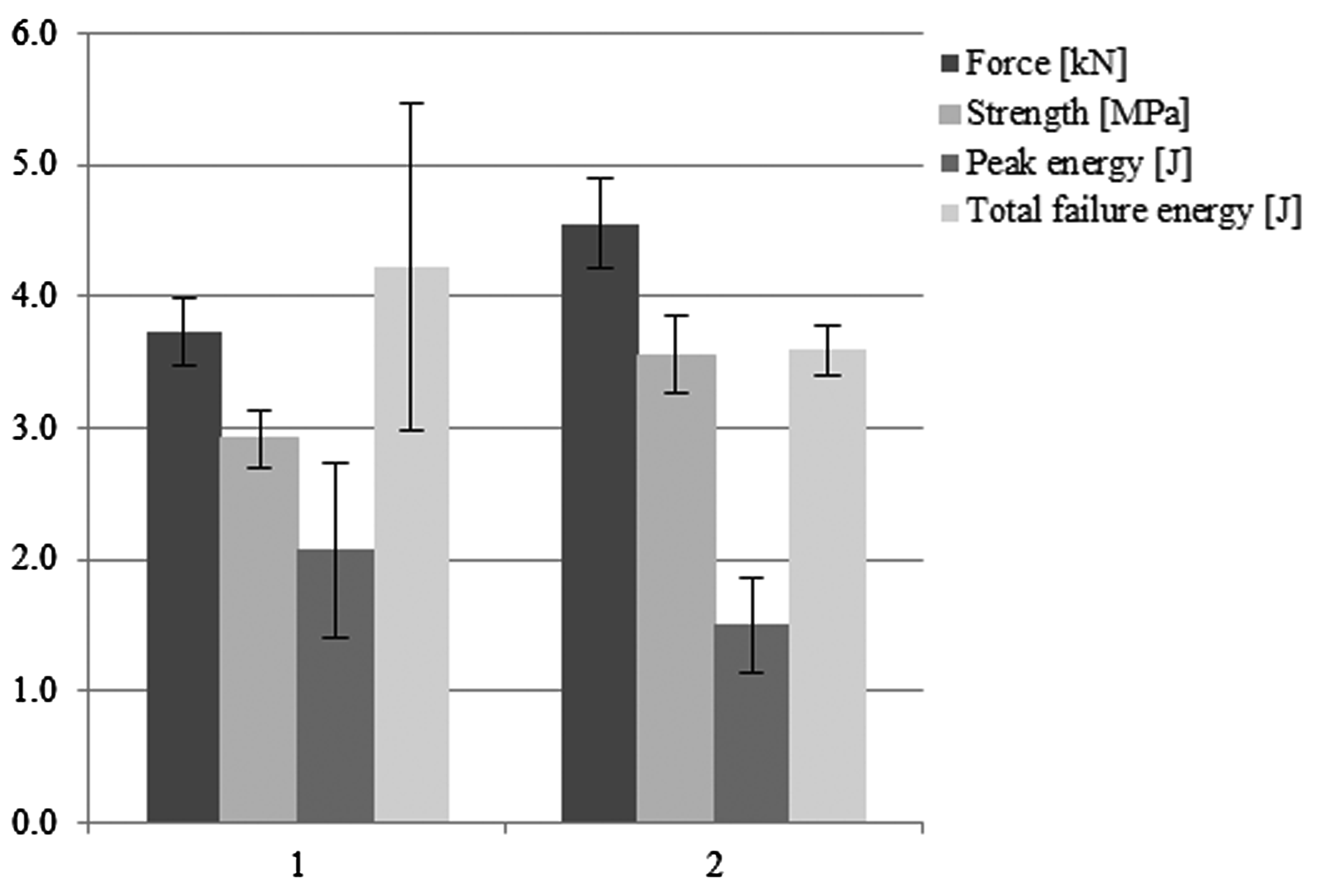
Failure modes. Fracturing is generally the major contributor for energy absorption capabilities of fibre-reinforced composites during impact, rather than plastic deformation. 16 Before the maximum load is reached, energy absorbed by the laminate is dissipated due to microcracking of the matrix. 28 Due to further increased crushing loads and developed strains, the density and extent of matrix cracks increases leading to interfacial fibre-matrix debonding24,28 due to the mismatch of fibre and matrix properties. 29 At the macro level, energy dissipation during crushing results from bending, deformation of the profile section and forming of fracture lines. 24 It is well-known that progressive material degradation reduces the bending stiffness of pultruded profiles, changes the deflected shape and causes the separation of the profile junctions. Hence, the fibres are unsupported due to interfacial debonding, leading to delamination and fibre breakage during deformation of a pultruded profile. 16
Figures 9 and 10 show typical load and absorbed energy versus displacement curves together with photographs of failure modes showing the characteristic deformation history of a pultruded box-beam section of Configuration 1 and 2, respectively. It can be observed that the absorbed energy during the initial crushing phase is for both laminates smaller compared to the phase after reaching the maximum load.
Typical load and absorbed energy vs. displacement curves with deformation history for a Configuration 1 section. Fracture details of a Configuration 1 section after calcination.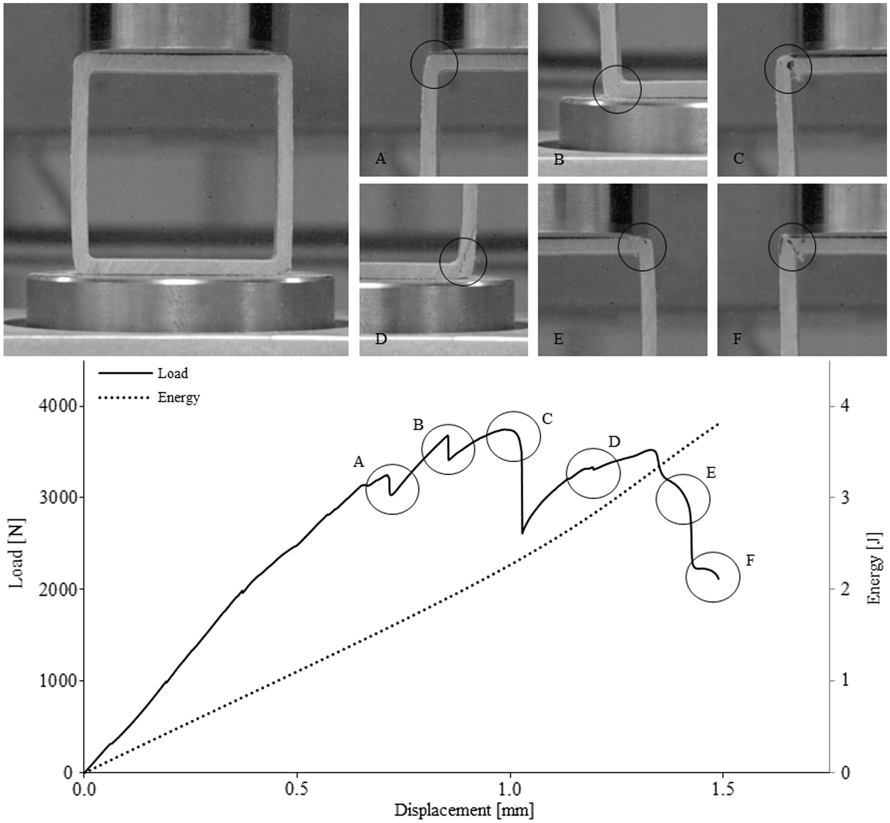
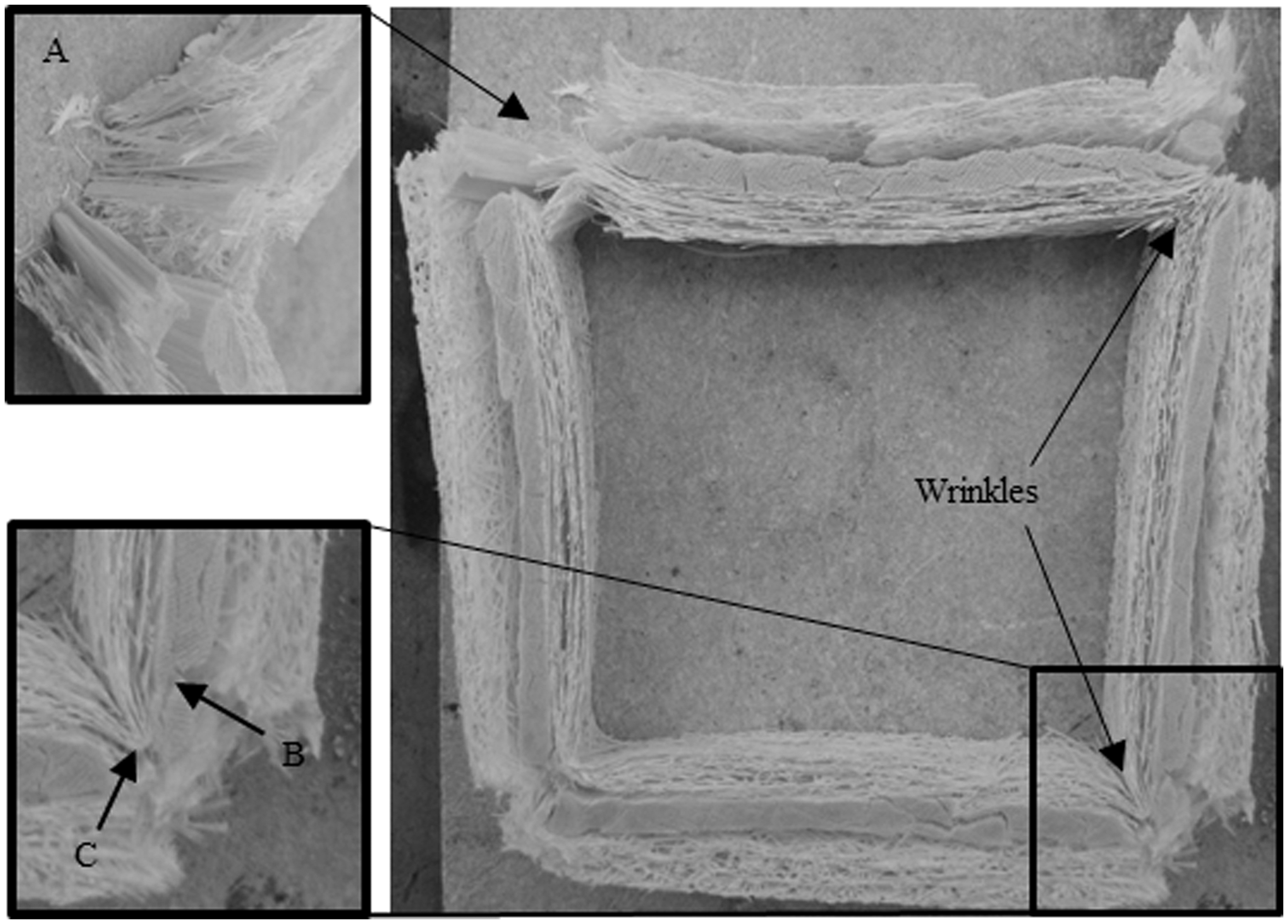
Occurring failure modes in Configuration 1 sections were matrix cracking and intra-yarn failure in the roving layer (see photo B in Figure 11, showing a tested Configuration 1 section after calcination), delamination between inner CSM and roving layer as well as cracking and fracturing in the profile junctions due to fibre breakage in CSM layers (see Figures 9 and 11, photo C and A, respectively). As sections made of Configuration 1 presented pre-existing defects, several relationships between defects and occurring failure can be deduced. A surface rupture along the section width induced 45° cracks in flange-web junctions. Although a pre-existing 45° corner crack promoted progressive cracking of junctions due to compression, only the combination of a 45° corner crack and a surface rupture induced fractures up to complete failure (see Figure 9, photo F). Chotard and Benzeggagh
20
observed that CSM layers provide a stopping effect on the crack growth, although the damage propagation is not totally prevented as cracks carry on causing delamination at the interfaces. This study revealed the same effect as shown in Figure 8, photo C, presenting an undamaged CSM layer wrinkle that stopped the crack growth of a pre-existing 45° rupture. Photo D in Figure 9 depicts occurring interface failure between inner CSM and roving layer in the section corner.
Typical load and absorbed energy vs. displacement curves with deformation history for a Configuration 2 section.
The final failure in Configuration 1 sections under compressive loading was the complete rupture of its corners. Several authors10,17,22 reported on the tearing failure in junctions of pultruded profiles due to high shear-stress concentrations in the corner zones. Chotard et al. 22 identified the junction between flange and web as the weakest point of a box-beam structure as manufacturing-induced defects coupled with high stress fields lead to a high failure probability.
The tested sections of Configuration 2 showed delamination at the corners between inner layers and roving layer, see photos A and B in Figure 10, intra-yarn failure between rovings see photo F and B in Figures 10 and 12, respectively, delamination in the profile webs between outer layers and roving layer as well as fibre breakage in outer and inner profile layers as shown in photo C and F in Figure 10 or A and C in Figure 12 due to flange or web buckling. Moreover, two opposing effects/mechanisms of failure phenomena could be observed during testing. Occurring flange buckling caused a reduction of delamination and crack growth in the corners, while corner delamination due to increased bending diminished buckling fracture. However, sections of Configuration 2 showed no tearing failure in the junctions. The final failure in Configuration 2 occurred due to flange or web buckling as a consequence of fibre-matrix debonding, in combination with matrix cracks and intra-yarn failure in the roving layer. The presence of + /−45 fabric improved the bending performance of Configuration 2 and reduced failure in the corners due to delamination. However, the occurrence of delaminations cannot be prevented with bi-directional fabrics due to poor interlaminar through-thickness shear resistance. Delamination along the profile webs may be attributed to improper shear transfer between fabrics as a result of shear strength mismatch between adjacent layers
2
as well as bending stiffness mismatch due to altering fibre orientations.
29
Fracture details of a Configuration 2 section after calcination.
Numerical analysis
As outlined in the Introduction of this article, the objective of the present numerical study is the prediction of experimentally tested failure behaviour of different pultruded box-beam sections with commercially available numerical tools and simple micromechanics equations.
Failure modelling
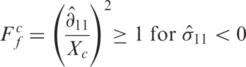
3D FE models were developed using the FE-code ABAQUS and its built-in damage model to study the influence of material properties on the mechanical performance. This damage model is based on criteria proposed by Hashin to predict failure onset in brittle fibre-reinforced composites. Hashin considers four different modes of failure, distinguishing between fibre and matrix as well as tension and compression failure:30,31
Tensile fibre failure mode

Compressive fibre failure mode
Tensile matrix failure mode
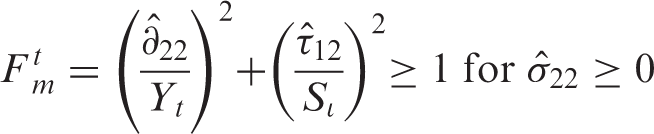
Compressive matrix failure mode

Kachanov
32
proposed that damage propagation can be characterised by degradation of material stiffness. The damage evolution within ABAQUS is based on the extended damage model for elastic-brittle fibre-reinforced composites, proposed by Matzenmiller et al.,
33
where the reduction of stiffness matrix coefficients is controlled by damage variables that can take values between zero (undamaged state) and one (fully damaged state).
34
When the stress state is determined and the onset of degradation is evaluated for each material point, the material response is computed from:
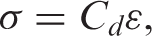

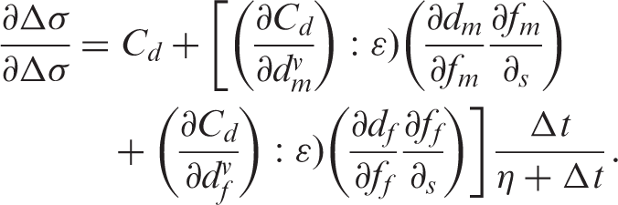
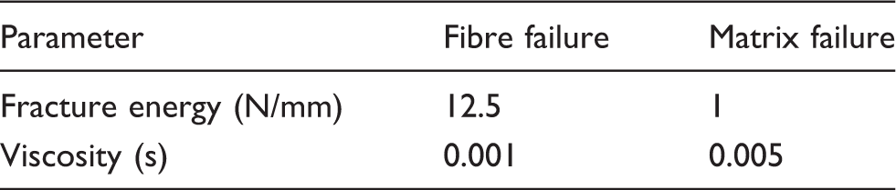
To improve convergence problems in the softening regime, the ABAQUS damage model offers a viscous regularization scheme, which causes the tangent stiffness matrix of the softening material to be positive definite for sufficiently small time increments.
31
Hence, the response of the damaged material is computed using regularized damage variables from:
FE-model
A non-linear analysis in ABAQUS/Standard with implicit time integration was used to calculate the quasi-static response of pultruded sections. The implementation of the Hashin damage model demands the use of elements with plane stress formulation. For a layer-wise failure analysis and its contribution to the overall performance, a 3D geometrical model with 22200 hexahedral continuum shell elements was created. An analytical rigid surface is used to model the circular loading block. The value for the vertical motion of the rigid surface is taken from the displacement data from the experimentally tested profile sections. The displacements of the bottom surface of the FE model is fixed in loading direction. A typical mesh definition for computations is shown in Figure 13. According to experimental tests, the corners are the critical spots; hence the mesh was locally refined at the junctions between flanges and webs. The mesh density in the corners was 8× increased.
FE mesh model of profile section.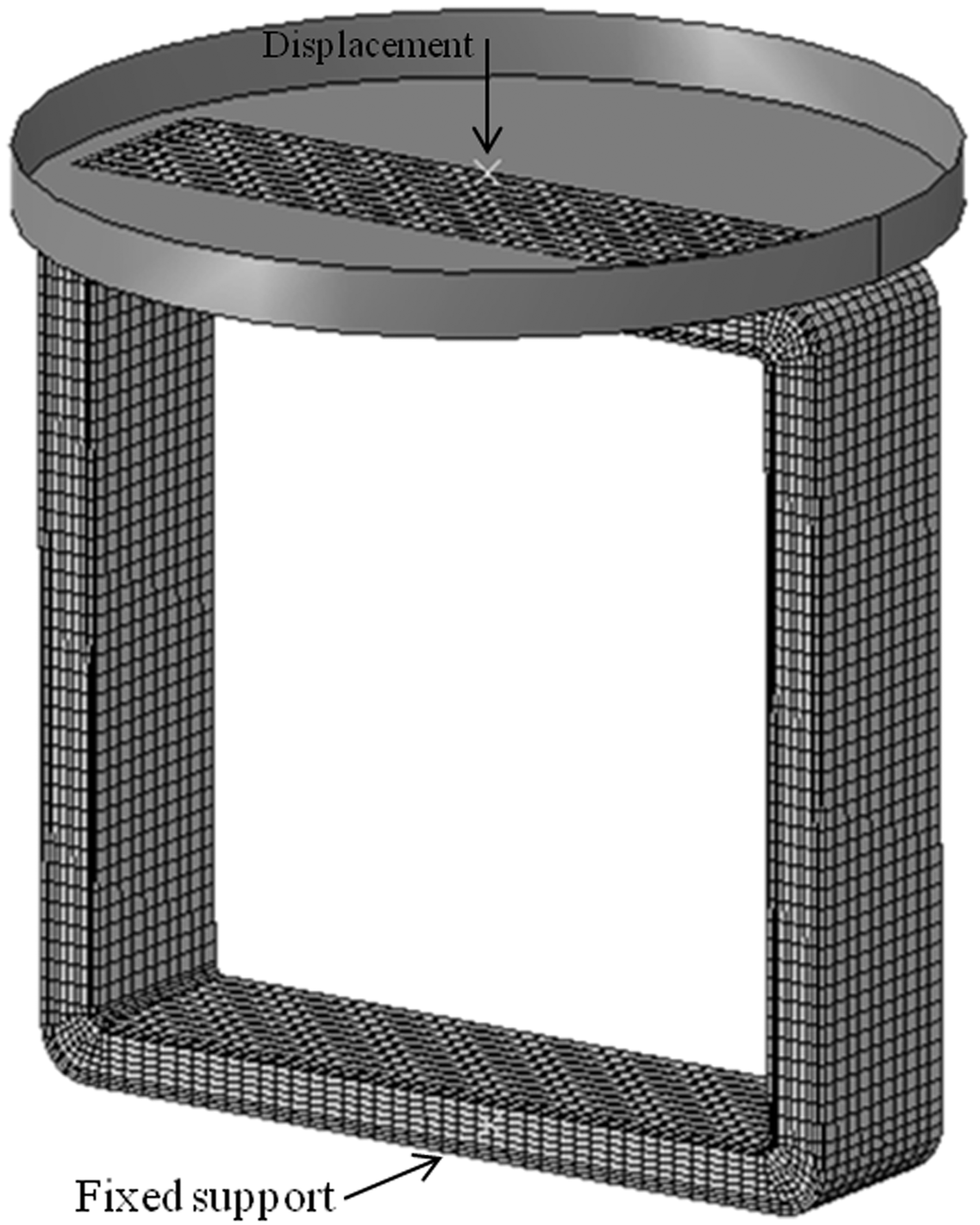
A further FE model of Configuration 1 was created to analyse the influence of pre-existing defects on the material behaviour. As the combination of 45° corner crack and surface rupture induced always fractures up to complete failure of a junction, an elliptic eye and surface cut were integrated in the upper left corner of the model. The elliptic defect is representing an enclosed void due to wrinkling during processing of the inner CSM layer. The dimensions of the eye in the FE model are 0.5 mm and 0.1 mm, major and minor ellipse axis, respectively. The triangular surface cut along the section width had a width of 0.1 mm and a depth of 0.15 mm.
Material properties
Pultruded composites are heterogeneous material systems with non-linear behaviour due to the fact that these profiles are mainly reinforced in axial direction to carry predominant axial loads.
7
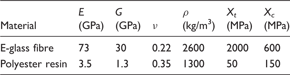
As mentioned before, even layer thicknesses as described in Table 1 are used for numerical modelling. In accordance with the pultruded lay-ups, the FE model of Configuration 1 is made of three layers and the model of Configuration 2 consists of five layers. Glass fibres and resin matrix are singularly considered as homogenous, linearly elastic, isotropic materials and are assumed to have the same values in all layers. The matrix volume is defined as a collective medium that includes additives along with voids and microcracks. Knowing the material data of glass fibre reinforcement and polyester resin in Table 2, the material properties of unidirectional, bidirectional and multidirectional layers were derived with micromechanics equations based on the rule-of-mixtures, using the fibre volume fractions given in Table 1. Young’s modules were estimated using an extended rule-of-mixtures:


Material strengths used in the FE analysis (in MPa)
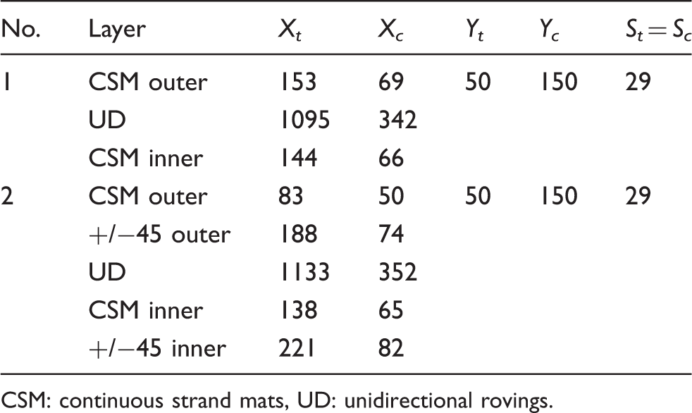
CSM: continuous strand mats, UD: unidirectional rovings.
A further objective of this FE analysis is to identify material parameters for improving the fracture toughness of pultruded GFRP profiles. From the above it can be observed that as many parameters depend on the tensile matrix strength this property becomes a critical parameter for the overall fracture toughness. Out-of-plane reinforcements are one obvious way to increase the transverse strength, and thus improve fracture toughness. For this purpose, analyses with single tensile matrix strength 1*Ytm and a tripled value 3*Ytm, leading to tripled shear strengths as well, were conducted.
Results and discussion
The numerical buckling behaviour of both profiles corresponds to the observed behaviour and occurring failure during mechanical testing. As the mean experimental displacement for Configuration 1 is bigger, higher compressive stresses occur at the bottom of the outer profile layer. As Configuration 2 presents a stiffer material behaviour, higher tensile stresses in loading direction occur in this model.
Delamination in the junctions occurred during mechanical testing in both profiles between roving layer and adjacent inner layers, as shown in Figures 9(D) and 11(F). Configuration 1 shows higher shear stresses than Configuration 2, however the highest shear stresses occur in both profiles in the junctions. A detailed study revealed that main shear stress differences in the FE models occur also between roving layer and adjacent layers. The highest shear stresses in the numerical models could be observed in Configuration 1 between the roving and inner CSM layer whereas in Configuration 2 between the roving and outer +/−45 NCF layer.
However, fibre damage in Configuration 2 in inner flange and outer web layers as seen in experiments, Figure 11(C) and (F), could not be observed in numerical analyses.
A comparison of further numerical analyses of both profiles, without damage model, subjected to the mean displacement of Configuration 1 showed that tensile and compressive stresses in loading direction are higher in Configuration 2 than in Configuration 1, as a result of the stiffer material behaviour. While in-plane shear stresses in Configuration 2 remained similar with increased displacement and much lower than in Configuration 1, the out-of-plane shear stresses increased significantly to the stress levels of Configuration 1. This comparison showed the importance of out-of-plane properties for the toughness of pultruded profiles.
Hashin failure analyses revealed that matrix failure is dominating the damage propagation in the studied pultruded profiles. Tensile matrix failure occurs mainly in the inner and outer web layers of both profiles. Furthermore, it occurs in the inner flange layers close to the corners and propagates due to buckling, through the corners. As the Hashin criterion for tensile matrix failure is governed by the transverse tensile strength Yt, it could be observed that an increased material parameter reduces failure in the inner layers and stops failure in the outer layers as well as the failure propagation through the corners. Compressive matrix failure occurs in all junctions of both profiles, mainly in the roving layer. In case of increased shear strengths, compressive matrix failure in the corners was stopped, see Figure 14. As the Hashin criterion for compressive matrix failure is influenced by the transverse compressive strength as well as shear strengths, the governing effect of increased shear strengths could be proved.
Final states of compressive matrix failure in Configuration 1 with 1 × Yt (a) and with 3 × Yt (b) and in Configuration 2 with 1 × Yt (c) and with 3 × Yt (d).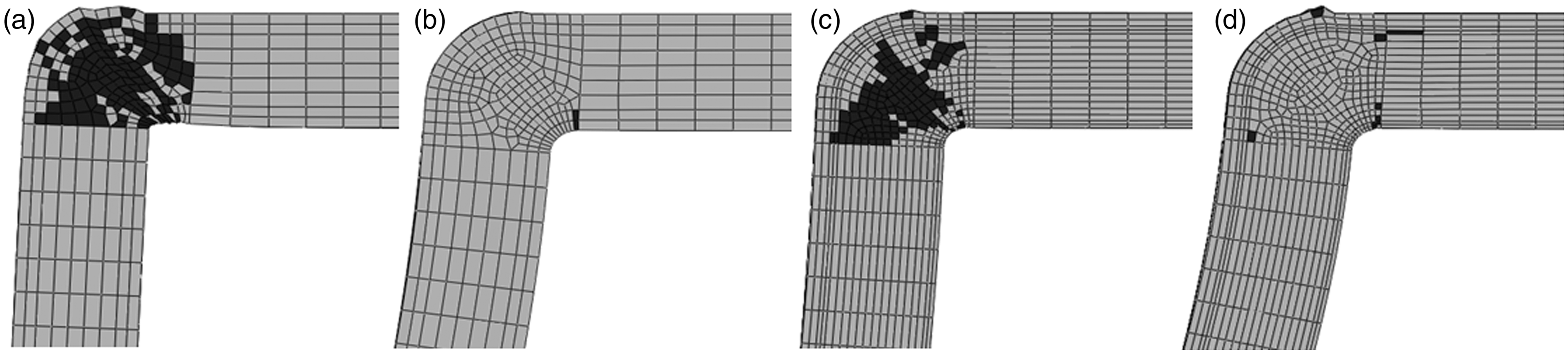
Furthermore, analyses showed that tensile fibre failure occurs in the inner section layers located at the corners, progressing through the thickness of the junctions similar to failure modes seen in experiments. The Hashin criterion for compressive fibre failure indicates in both profiles corner damage in the outer CSM layer due to the influence of the loading plate and compression on the support.
Generally, matrix cracking in tension and compression occurs due to a combination of transverse and shear stresses. Therefore, high shear stress concentrations in the corners in combination with occurring matrix failure as identified in numerical analyses lead to further damage such as fibre debonding, hence causing delamination as observed for both profiles in the experiments. As discussed before, progressive material degradation reduces the bending stiffness of pultruded profiles, causes a separation of profile junctions and changes the deflected shape. In analogy to experimental results, the final failure mode in Configuration 1 is cracking and fracturing of the profile junctions, resulting in vertical sliding of the upper flange, see Figure 15(a), similar to the experimentally tested section in Figure 9(C) and (F), whereas Configuration 2 presents no tearing as shown in Figures 15(c) and 11.
Buckling modes of Configuration 1 without defect (a), with elliptic hole and surface cut (b) and Configuration 2 (c) under compressive loading.
Experiments showed that a combination of 45° corner crack and surface rupture promoted progressive cracking of junctions. The FE analysis of Configuration 1 with an elliptic hole in the roving layer and triangular surface cut at one inner corner shows the influence of pre-existing defects on the fracture behaviour. Occurring failure is particularly located on the side with the defect, explaining sliding and stronger buckling to the defected section side, as shown in Figure 15(b), which was experimentally observed in Figure 9(C) and (F). Due to sliding of the flange shear stresses, located around the defect, increase and main stresses decrease compared to a profile without defect, however the highest tensile stresses occur in the inner layer of the opposite upper corner
Comparing the experimental and numerical load-displacement curves of Configuration 1, an initial analogy in the stiffness behaviour can be observed (see Figure 16), however maximum force and strength are overpredicted. These differences can be attributed to pre-existing defects in the tested sections, as the load-displacement curve of the model with incorporated defects in just one section corner presents faster damage propagation with lower forces.
Numerical load-displacement curves of Configuration 1.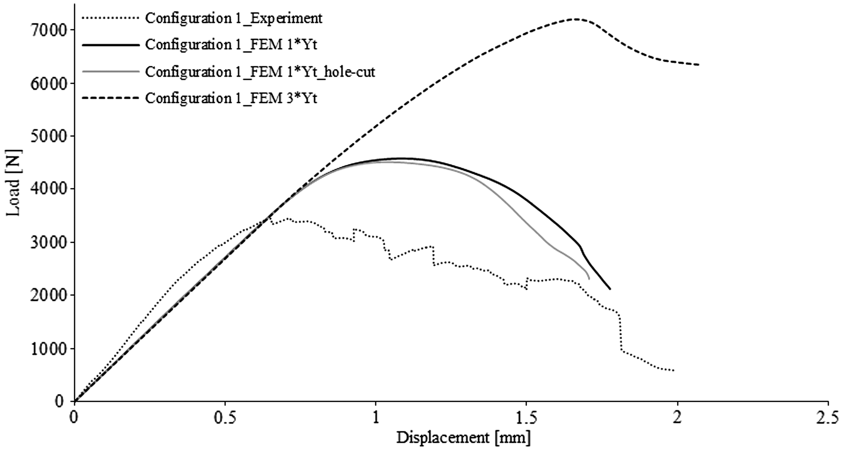
The comparison of experimental and numerical load-displacement curves of Configuration 2 shows that the calculated stiffness underestimates the experimental behaviour (see Figure 17). However, here, the maximum crushing load and strength are well-predicted. Comparing the curves of Configurations 1 and 2, the longer lasting load bearing capacities of Configuration 1 can be observed, resulting in a bigger displacement.
Numerical load-displacement curves of Configuration 2.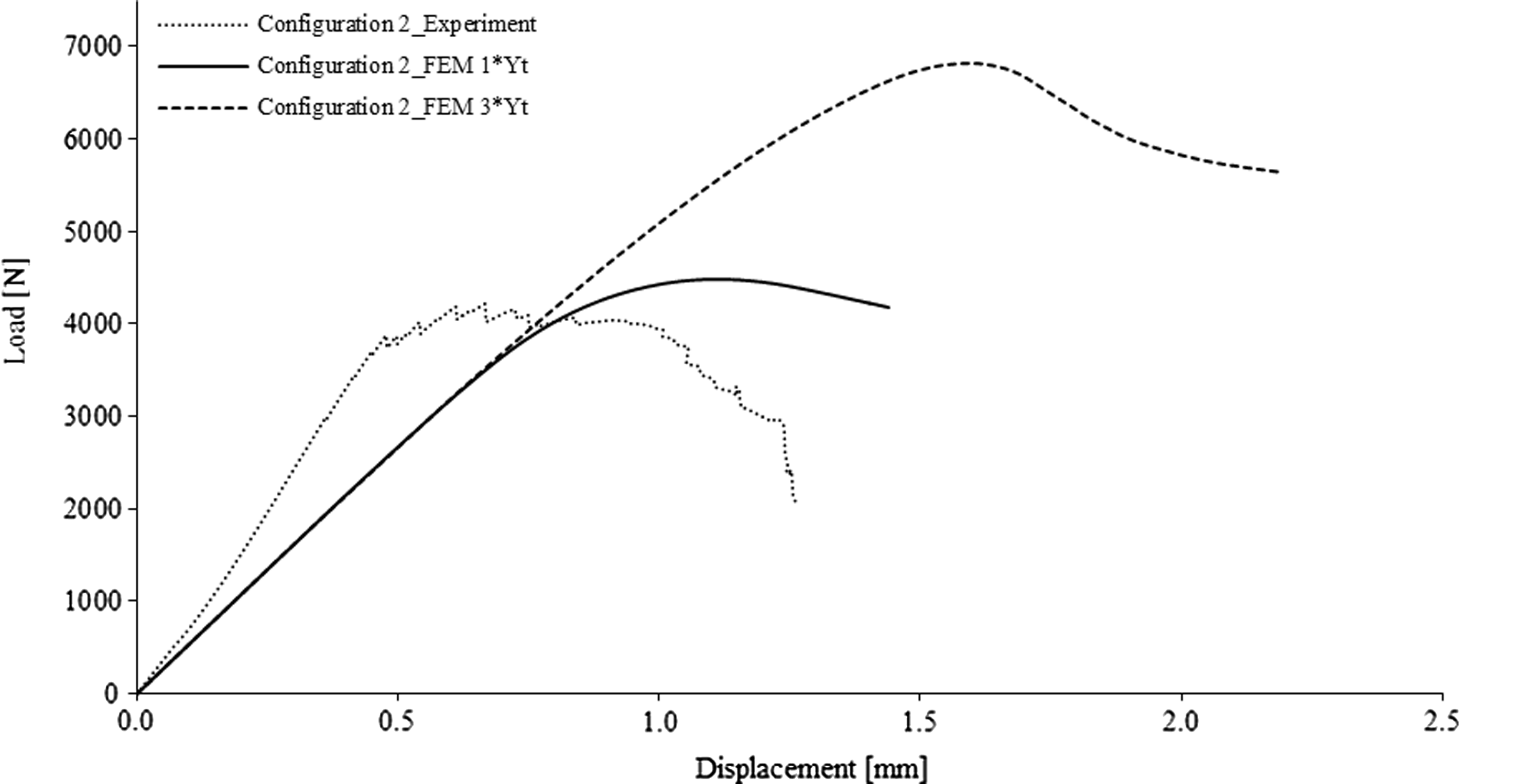
Matrix cracking is mainly contributing to energy dissipation under compressive loading. Further energy absorption during crushing results from the deformation of the profile and the forming of fracture lines. Conformity between experimental and numerical energy characteristics can be observed for Configuration 1 with single Ymt, whereas properties of Configuration 2 are overestimated, see Figure 18, related to differing numerical loads and displacements. Therefore, an exact comparison of both profiles with increased Ymt, to simulate the effect of out-of-plane reinforcements, is difficult as the mechanical behaviour could not be predicted correctly. However, it can be assumed that SEA with increased Ymt could be improved as shown in Figure 18.
Comparison of numerical and experimental energy absorption capacities of Configurations 1 and 2.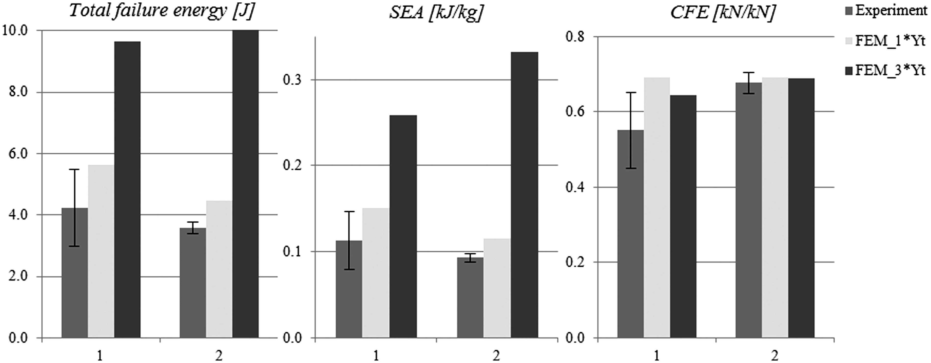
As mentioned before, numerical studies with increased transverse tensile and shear strengths showed that matrix failure and
Conclusions
Pultruded profiles are mainly reinforced in the longitudinal direction for a use under axial loading. Additional reinforcements are added for smooth surface finishes and to cope with transverse loading, however reinforcements for particular out-of-plane properties are missing. Results of an experimental and numerical study to evaluate damage initiation and progression in pultruded box-beam structures subjected to lateral compression, using the built-in Hashin damage model of ABAQUS, are presented. Effects of pre-existing material imperfections due to manufacturing are investigated as well.
The junctions between flanges and webs are the weakest points of a box-beam section under lateral compression. High shear stress concentrations in combination with occurring matrix failure lead to further damage such as fibre debonding, hence causing delamination as observed for both profiles in the experiments. Imperfections in corners increase tearing failure probability.
It was shown that the Hashin damage model in ABAQUS can be used for qualitative predictions of occurring failure: predicted damage, buckling as well as failure modes, corresponds with observed experimental results, however material stiffness is consistently underpredicted. Despite, the model can be considered as a tool for profile designing regarding reinforcing effects of varying lay-ups.
The study finally shows that enhanced out-of plane properties, such as transverse tensile and shear strength, allow for tailoring shear damage and improving fracture toughness of pultruded GFRP box-beam structures subjected to lateral compression loading. Thus, considering changes in materials and manufacturing, the use of pultruded profiles can be expanded to non-axially loaded structures.
Footnotes
Acknowledgements
One of the authors (FR) acknowledges the personal grant received from the Portuguese Foundation for Science and Technology (FCT) (ref. SFRH/BD/66899/2009).