
Abstract
A group of nickel-coated carbon fiber reinforced Stellite 25 composites are produced using the hot isostatic pressing technique. The focus of this research is on obviating the problems related to the presence of carbides in Stellite alloys by substituting carbides as the main strengthening agent in Stellite alloys with nickel-coated carbon fibers. The principal reason for selecting Stellite 25 is because of its low carbon content and thereby relatively carbide free microstructure. The nickel coating is intended to eliminate any chance of carbide formation due to the possible reaction between carbon fibers and the matrix alloying additions. The tribomechanical and corrosion properties of the composites are characterized. The results show that the composites exhibit better corrosion resistance than medium-carbon Stellite alloys. The addition of carbon fibers into Stellite 25 improves its hardness and tribological properties. The wear rates of the composites are lower than that of medium-carbon Stellite alloys and comparable with that of high-carbon Stellites.
Keywords
Introduction
Cobalt-based superalloys are a group of important industrial materials with excellent high-temperature corrosion resistance. In addition, these alloys display unique combination of mechanical and tribological properties at elevated temperatures. 1 Stellite alloys are a range of cobalt-based superalloys with the main constituents belonging to the quaternary systems Co–Cr–W–C or Co–Cr–Mo–C. These alloys are generally strengthened by the precipitation of carbides in their cobalt matrix. The most important differences among the current Stellite alloy grades are their carbon and tungsten contents, which affect the type and amount of carbide formation in the microstructure. 1 In terms of the volume fraction of carbides, there are two major groups of Stellite alloys: high-carbon alloys such as Stellite 1, Stellite 3, and Stellite 720 and low-carbon alloys including Stellite 21 and Stellite 25. Normally, the wear resistance increases with the higher volume fraction of carbides while the ductility improves with lower carbon content. 1
Despite the fact that many types of carbides can improve the tribocorrosion and mechanical properties of Stellite alloys, the existence of carbon in these alloys has its own difficulties/disadvantages. The problems associated with the presence of carbon in Stellite alloys can be summarized as formation of unwanted intermetallic compounds and/or carbidic phases;2,3 oxidation of carbides; 4 transformation of carbides; 4 and inhomogeneous distribution of carbidic phases.4,5 Unfortunately, the presence of unwanted intermetallic compounds and carbidic phases in Stellite alloys is inevitable and the type, size, shape, distribution, and amount of desired carbides cannot be easily predicted or controlled. This is because the carbide formation process in Stellite alloys is a function of many factors, including alloying element types and fraction, carbon content, fabrication technique, sintering heating and cooling rates, and operational parameters.
To obviate the problems related to the presence of carbon in Stellite alloys, it was decided to substitute the main strengthening agent in Stellite alloys, i.e. carbides with nickel-coated carbon fibers (CFs). A recent study 6 has demonstrated that the plain carbon fiber addition can lead to a noticeable improvement in the tribological properties of Stellite alloys including their anti-friction properties. In addition, it was observed that the plain carbon fiber addition could make Stellite alloys considerably more resistant to abrasive wear. Carbon fibers have very useful engineering properties including high mechanical properties, good chemical inertness, excellent electrical and thermal conductivities, outstanding thermal stability, and low density. 7 These properties can be readily translated into great flexibility in formulating composites with outstanding specific performance. Using the idea of metal matrix composites (MMCs), nickel-coated carbon fibers were proposed to be employed as reinforcing elements in Stellite alloys. The objective of this research was to study the effects of nickel-coated carbon fiber incorporation in a low-carbon Stellite alloy and to characterize the mechanical, tribological and corrosion properties of the MMCs produced by using the hot isostatic pressing (HIP) routine. The nickel-coating on the carbon fibers serves three intended functions. One is to enhance the interface bonding between the carbon fibers and the matrix. The second is to prevent diffusion of carbon from the carbon fibers into the matrix, thus avoiding formation of carbides in the matrix. The third is to alleviate redox reactions including carbon oxidation and carbon reduction at elevated temperatures during manufacturing process or final service.
Material fabrication
Raw materials
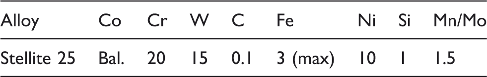
Nominal chemical composition (wt%) of Stellite 25. 8
Physical and mechanical properties of Stellite 25. 8
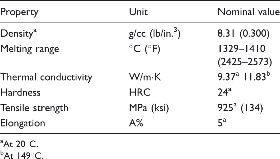
At 20℃.
At 149℃.
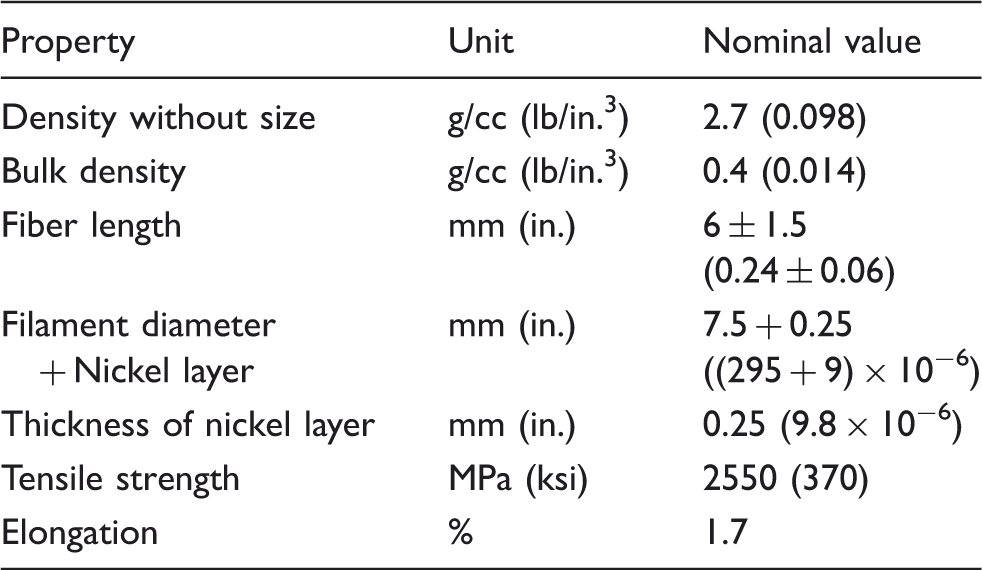
Physical and mechanical properties of Ni-coated carbon fiber at room temperature. 9
Powder metallurgy process
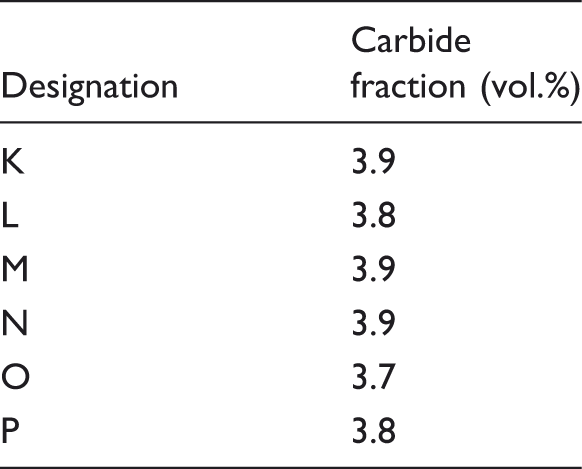
In this research, pure Stellite 25 specimen and six composite specimens having different contents of carbon fiber, listed in Table 4, were fabricated using the powder metallurgy (PM) process. In these compositions, carbon fiber content varied between 0.25 and 10 wt%. Specimen A was used to measure the properties of pure Stellite 25 and to confirm that the fabrication parameters were selected properly. Composites K, L, M, N, O, and P were designed to investigate the effects of incorporation of the chopped nickel-coated carbon fiber and its content level on Stellite 25. In the PM process, round tubes of stainless steel-grade 316 having 40 cm (15.75 in.) length and 1.5 mm (0.06 in.) wall thickness, with the inside diameter of 1.7 cm (0.67 in.), were used as consolidation containers of the specimens. The HIP and sintering cycle parameters were selected in accordance with the published data for the powder metallurgy of cobalt-base superalloys.1,3,10–13 The PM route, including HIPing at an elevated temperature of 1150℃ (2102°F) under a pressure of 150 MPa (21.75 psi) of argon gas for about 2.5 h was adopted in fabrication of all the specimens. The detailed sintering cycle is presented in Figure 1.
Sintering cycle for the specimen fabrication. Chemical compositions of Stellite 25 and Stellite 25-based composites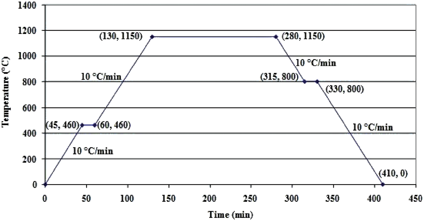
Material characterization
Microstructural analysis
Microstructural analysis of the fabricated specimens was performed using light microscopy technique. Prior to the microscopic observation, the surface of each specimen was prepared by grinding and polishing operations. After polishing, the specimens were subjected to electrolytic and immersion etchings with two different solutions. Because all constituent materials of the composites are corrosion resistant, vigorous etching reagents were necessary to optically enhance microstructural features. The etching reagent includes 2% chromic acid (H2CrO4) with 98% water (H2O).1,14
Carbide volume fraction analysis
To measure carbide volume fraction in the specimens, an image analysis software package called Clemex Vision™ was used. For each specimen, 15 different pictures were analyzed which consisted of five pictures for each magnification (50×, 100×, and 200×). The identified phases included a dark phase representing the carbidic phase and a bright gray phase showing the background matrix phase of the specimens. The carbide area fractions were converted to the carbide volume fractions based on the Delesse principle stating that the area fraction of a nonclassically shaped component relative to the entire area is an unbiased estimate of the volume fraction of the component in the object. 15
Density measurement
Immersion density technique was employed using a Sartorius 6080 electronic balance to determine the density of each specimen. This technique is based on Archimedes principles. The test procedure was in accordance with the ASTM Standard B 311-08. 16
Corrosion test
Superalloys may become corroded in several different ways. These alloys might be attacked by oxidizing environment at ordinary or high temperatures, different types of salts in the air necessary for combustion, for instance, and various corrosive aqueous media such as mineral or organic acids. Also, hot corrosion may occur in gas turbines, incinerators, and boiler tubes due to the use of sulfur- and sodium-containing fuels.1,11 To satisfy the industrial need for outstanding corrosion-resistant materials, immersion tests were employed to evaluate the corrosion resistance of the fabricated materials in accordance with the ASTM Standard G 31-72.
17
The surfaces of the specimens were polished to 0.05 µm finish, cleaned in ultrasonic bath, and air-dried, according to the ASTM Standard G 1-03.
18
The polished specimens were immersed in the corrosive solution of oxidizing acid 65% HNO3 at its boiling temperature for 72 h. These conditions were selected to represent a worst-case situation as a guide rather than reproducing a certain environment. The specimens were removed from the test medium, cleaned by soft brushing under warm tap water, and dried with ethanol and a blow dryer. Each specimen was weighed before and after the test to measure the average corrosion rate of the specimen using the following equation based on the ASTM Standards G 1-0318 and G 31-72
1
7

Hardness test
Rockwell hardness test was conducted in accordance with the ASTM Standard E 18-08b 19 in the standard laboratory atmosphere with a Wilson® Series 2000 Rockwell machine. Rockwell is considered as an empirical indentation hardness test that might be useful in selection of materials and quality control. The test result may also correlate to some other characteristics of the specimens such as tensile strength, wear resistance, and ductility. Each designation was subjected to at least 10 different hardness measurements and the average of these measurements was reported as the hardness value of the specific designation in the present research. The test specimens were 10 mm (2.54 in.) in thickness with smooth and even surfaces at the top and on the bottom. The tests were conducted using a diamond spheroconical indenter with the preliminary test force of 10 kgf (98 N) and the total test force of 150 kgf (1471 N) as the test parameters.
Wear and friction tests
A very important feature of superalloys is their wear resistance properties; therefore, the tribological behavior of the developed materials was investigated using a TEER-POD-2 computer-controlled pin-on-disk tribometer. The pin used in this research was a 5 mm diameter AISI 52100 steel ball supplied by TEER Coating Limited, with the hardness of 60-67 HRC (697 and 900 Vickers). The disk was the tested specimen cutting from the HIPed materials with 10 mm thickness. All the specimens were polished to 0.05 µm finish, cleaned in an ultrasonic bath, and then dried. The weights of these specimens were recorded to an accuracy of 0.0001 g before the wear test. The tests were conducted in the standard laboratory atmosphere under a dry-lubricating condition and in accordance with ASTM Standard G 99-05.
20
The testing parameters included the load of 10 N, relative sliding speed of 0.1 m/s, accumulated sliding distance of about 500 m, and the test duration of 83 min. To understand the wear mechanism of the developed materials and investigate the effect of the reinforcement on the friction and wear behavior of the composites, the worn surfaces of all the specimens were examined by optical microscopy. The following data were obtained from the test according to the ASTM Standard G 99-05.
20
Wear loss: After each test, the disk specimen was cleaned by soft-brushing under warm tap water to remove debris generated during the wear test, dried, and weighed to an accuracy of 10−4 g. Using the formula expressed below, the volume losses of specimens due to the wear were obtained
Wear factor: The following equation was used to calculate the wear factor or the specific wear rate of each specimen
Friction coefficient: Using a linear variable displacement transducer, the variation of the coefficient of friction (μ) with time of the specimens was automatically recorded.
Results and discussions
Microstructure
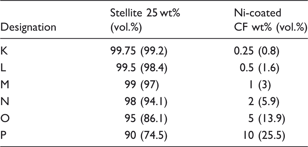
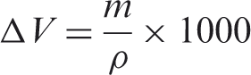
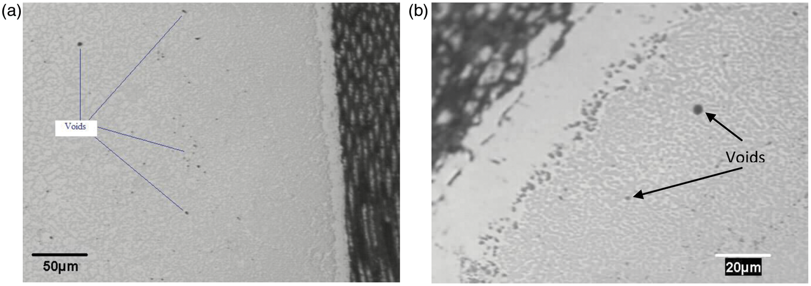
The micrographs of the specimens are presented in Figure 2. It is observed that the pure Stellite specimen and all the developed composites exhibit the very similar fine grayish matrix microstructures. The presence of porosity in the matrix is visible, as seen in Figure 3. This was mainly caused by the sintering process because of the point contacts between the necked particles.
13
However, as the amounts of voids are very small, it is reasonable to conclude that the fabrication parameters were selected properly.
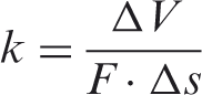
Microstructural images: (a) matrix of unetched specimen A; (b) carbon fibers and matrix of an unetched composite; (c) matrix of an etched composite in an area close to the fibers. Presence of voids in the developed composites: (a) at lower magnification and (b) at higher magnification.
With the use of the aforementioned etching solution, carbides can be easily distinguished in the matrices due to their blackish color compared with the matrix color. The carbide morphology and distribution are comparable to the micrographs published in other references.1,12,21 Figure 4 presents an exemplary picture used for carbide fraction analysis. Also, the volume fractions of carbides in the specimens are shown in Table 5. It is shown that the carbide volume fractions in all specimens are very close. In other words, neither adding nickel-coated carbon fibers to the Stellite alloy nor raising the amount of the fiber in the composites has any noticeable effect in increasing the carbide content. Therefore, it can be inferred that the nickel coating of the fibers inhibited carbon diffusion at the high temperature during the sintering process.
Exemplary picture used for the carbide volume fraction analysis. Carbide volume fraction in different specimens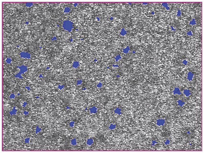
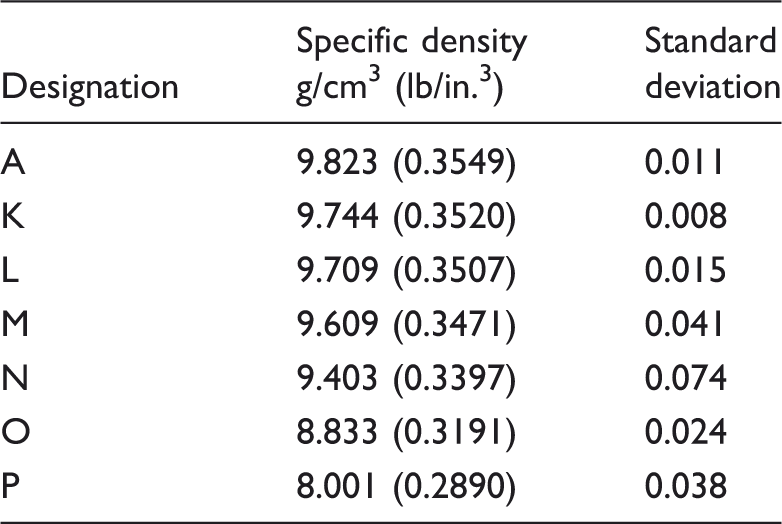
Density
Specific densities
Hardness
The hardness test results are presented in Figure 5. Compared with the hardness value of cast Stellite 25 alloy, provided by the manufacturer in Table 2, specimen A which was fabricated by the PM route shows about 41% increase in hardness. This increase was owing to the use of HIP/sintering process as the fabrication method, which naturally results in a material with lower porosity and higher density.
11
Furthermore, it is seen that the hardness of the pure Stellite alloy specimen is enhanced (up to 57%) by the addition of carbon fibers. As the fiber content increases, the hardness of the composite increases as well. In particular, composite P, with the largest amount of carbon fiber, exhibits the highest hardness of 53.3 HRC. This improvement can be explained by the highest proportion of the fiber which has higher hardness than the matrix material.
Rockwell hardness test results.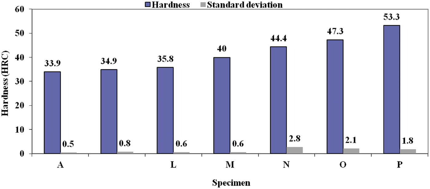
Corrosion
Figure 6 illustrates the corrosion rates of all the specimens in mils per year. The results show that the corrosion rate of the pure Stellite 25 specimen is lowest among the specimens. Between the composites, specimen P shows the highest corrosion rate with a value of 597 mils/year. However, compared with the corrosion-resistant medium-carbon Stellite alloy, Stellite 6B, which has a corrosion rate value of 985 mils/year for the same test condition,
22
specimen P shows better corrosion resistance. Considering the fact that the relationship between the corrosion resistance of Stellite alloys and their carbon content is normally inverse,
22
this behavior is more interesting when the carbon contents in Stellite alloys and in the developed composites are compared. For instance, composite P contains 10 wt% carbon fiber (carbon) while Stellite 6B contains only 1 wt% carbon. Therefore, the carbon in the alloy forms carbides with the alloy elements, which deteriorate the corrosion resistance whereas the carbon fibers in the composite do not induce carbides. In addition, the good corrosion resistance of the composites may be attributed to the high corrosion resistance of both Stellite 25 and carbon fibers. It should be again noticed that the intention for the use of such highly corrosive environment was not to duplicate a practical condition of exposure but to demonstrate the good corrosion resistance of the developed composites. This is because corrosion is a complicated process, which depends not only on the environment of the exposure but also on the chemical composition of the exposed material.
Corrosion resistance test results.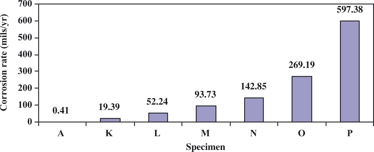
The corrosion mechanisms of the composites include galvanic corrosion and aqueous corrosion (surface oxidation). Galvanic corrosion happens because dissimilar materials possessing different surface potential are electrically coupled in the conductive corrosive media. 23 While the conductive corrosive media is the dilute boiling nitric acid, the dissimilar materials include the matrix alloy, the nickel coating on the carbon fibers and conducting nonmetal of carbon fibers. Since graphite (carbon fiber) is placed almost at the top of the galvanic series as one of the noblest materials, both nickel coating and the matrix material become anodic to the fibers. Also, between the nickel coating and Stellite 25 alloy, the matrix material becomes cathodic. Thus, nickel coating takes the form of galvanic anode to control the corrosion of the matrix with the mean of cathodic protection. Therefore, the galvanic corrosion of Stellite 25 only happens after the nickel coating decays. Another involved corrosion mechanism is aqueous corrosion caused by electrochemical reactions between the corrosive media of dilute boiling nitric acid, the matrix material and the fibers resulting in a form of degradation in the composites. It can be observed that the corrosion rate increases with increasing the fiber content. The reason lies in the increased contact area between the corrosive media and the composite material due to the higher void content in the composites as discussed above.
Tribological properties
The variations of the friction coefficients with the sliding time of the specimens determined in the pin-on-disc wear tests are presented in Figure 7. For each specimen the coefficient of friction increases initially and then decreases until it reaches a nearly constant level. The constant value of friction coefficient for the pure Stellite specimen is about 0.31 after 50 min sliding, whereas those of the developed composites vary in a range of 0.14 < µ < 0.2. It is clear that adding carbon fibers in the Stellite alloy greatly reduces the friction. This can be attributed to the formation of a thin solid lubricating film consisting of graphite and metal oxides on the counter surfaces. This behavior is in agreement with the investigations made by other researchers.24–28 Carbon fiber is composed of microcrystals of graphite, which is known as a good solid lubricant. Under the repeating operation of friction force during the sliding process, carbon fibers are milled into fine graphite particles which generate the thin film on the moving surfaces. This film prevents direct metal-to-metal contact between the two counterfaces. It should be noticed that the thin film generation in these composites happens gradually since the nickel coating of the fibers should be ground first. The film forms only after the nickel coating is worn off and the carbon fiber is exposed to the contact surface.
Variations of friction coefficient with sliding time.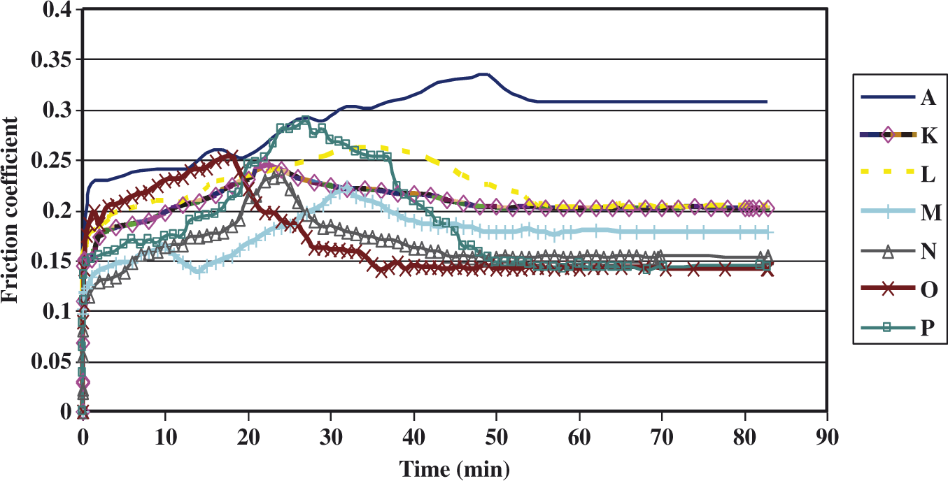
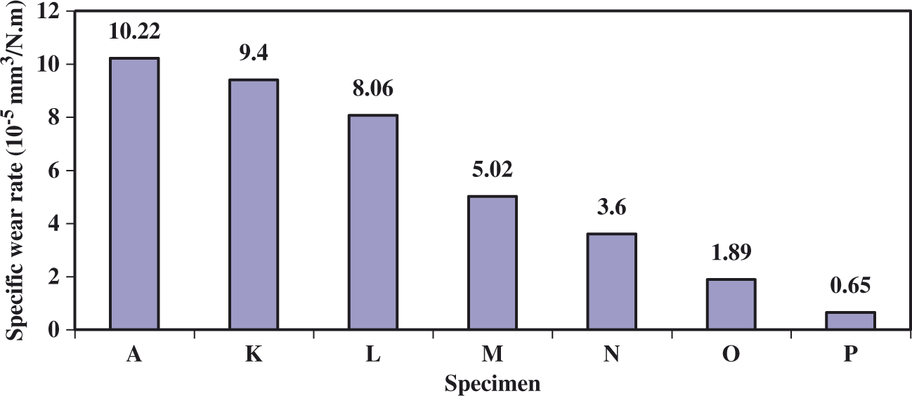
The wear losses of materials represented by the volume losses of the specimens in the wear tests are illustrated in Figure 8. The specific wear rates are reported in Figure 9. It is shown that addition of carbon fibers can make a remarkable improvement (up to one order of magnitude) in the wear resistance of Stellite 25. Composite P exhibits the highest wear resistance among all the composites with a specific wear rate of 0.65 × 10⁻⁵ mm3/N.m. The wear resistance of the base Stellite alloy is increased by about 16 times due to addition of carbon fibers for composite P. With the same wear test parameters, the specific wear rate of composite P is less than that of the sintered Stellite 694 (medium carbon) and comparable with the specific wear rate of the sintered Stellite 712 (high-carbon alloy).
12
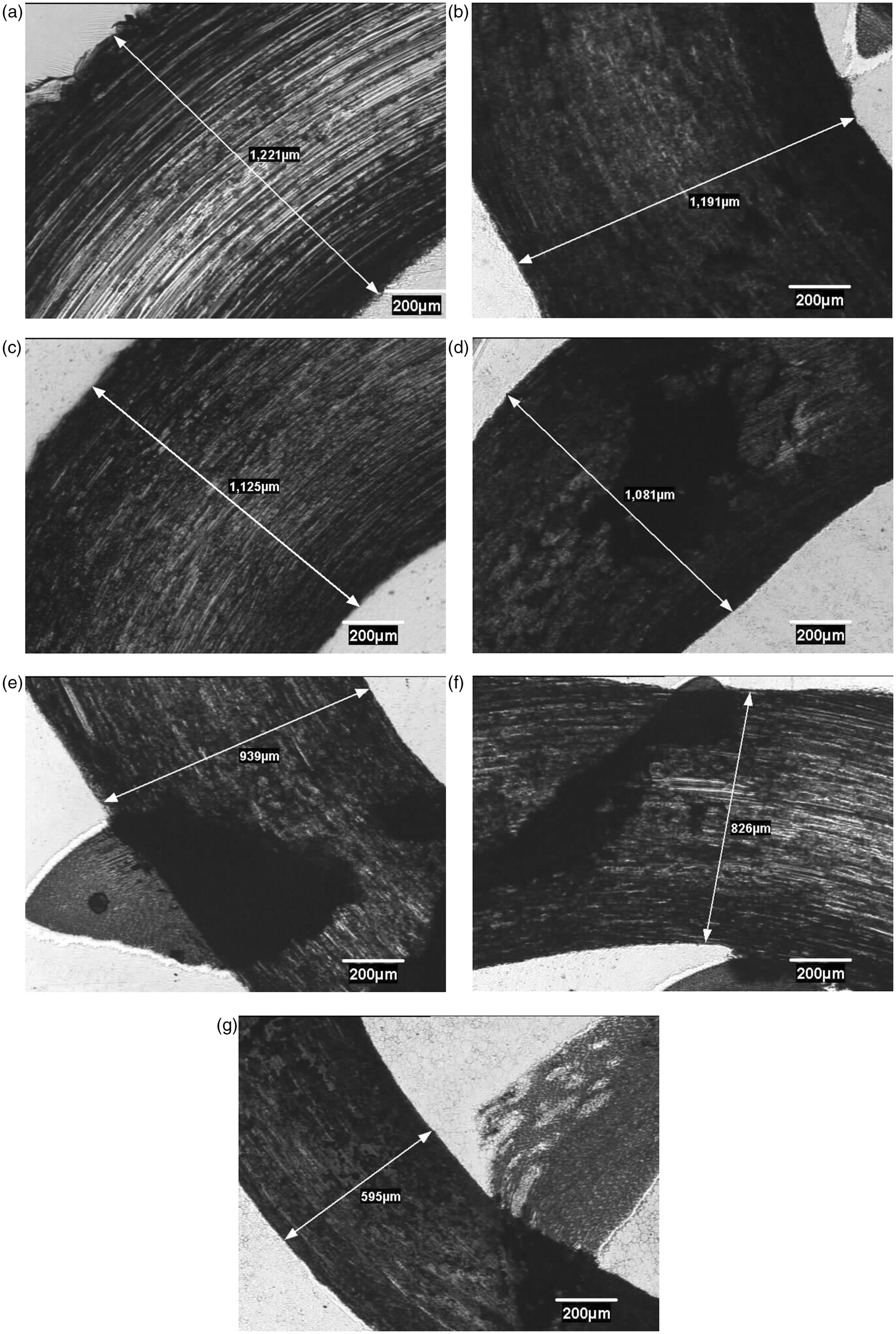
The micrographs of the worn surfaces obtained by optical microscopy are shown in Figure 10. It can be observed that the widths of the wear tracks of the composite specimens are much less than that of the pure Stellite 25 specimen, which corresponds to the results of wear loss and specific wear rate. It is also observed that the surfaces of the composite specimens exhibit obviously less damage than that of the alloy specimen.
Volume losses of the specimens under pin-on-disc wear. Specific wear rates of the specimens under pin-on-disc wear. Worn surfaces: (a) specimen A; (b) specimen K; (c) specimen L; (d) specimen M; (e) specimen N; (f) specimen O; (g) specimen P.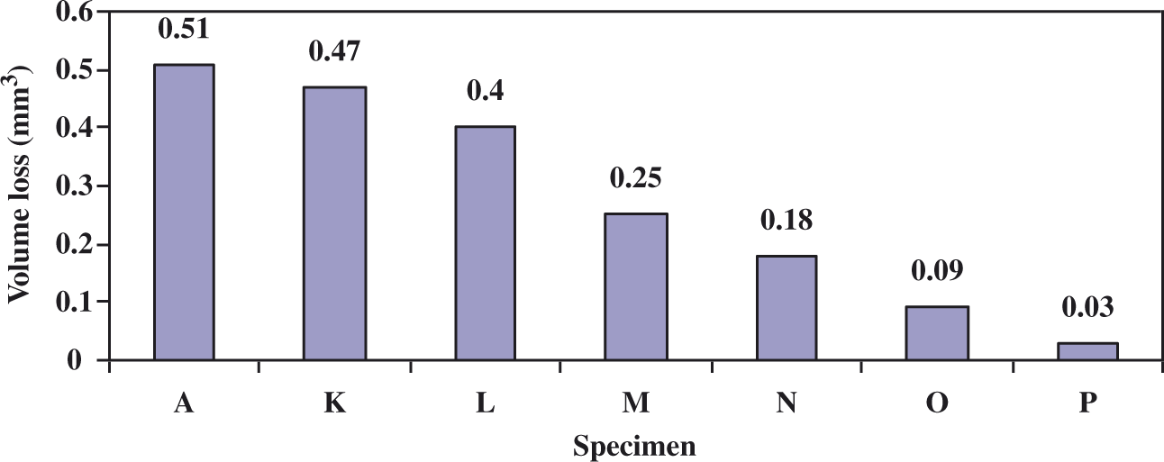
Discussion
Although a previous study 6 indicated minor increase in carbide volume fraction when plain carbon fibers were added to Stellite 25, the microstructural analyses indicated that the presence of nickel-coated carbon fiber did not induce any carbide in the Stellite 25 alloy matrix at the high temperature of the powder metallurgy process. This can be attributed to two main aspects: one is that carbon fiber is stable even at high temperatures and the other is that the Ni coating helps to prevent the diffusion of carbon fiber into the alloy matrix. Therefore, the Ni coating on the carbon fibers, as an isolator between the carbon fiber and the alloy matrix, did prohibit carbon diffusion, which avoided formation of carbides. In other words, the Ni coating on carbon fibers can lead to elimination of the detrimental effects of carbides in Stellite alloys, when carbon fibers are incorporated.
The corrosion test demonstrated that the developed composites have better corrosion resistance than medium-carbon Stellite alloys. Even the specimen with 10 wt% nickel-coated carbon fiber exhibited better resistance to corrosion than Stellite 6 containing 1 wt% carbon. This is because the key factor that affects the corrosion behavior of Stellite alloys is the carbides precipitated in the alloy matrices due to the presence of carbon. Thus the amount of carbides in the alloys controls their corrosion performance. At 1 wt% carbon (Stellite 6B), the carbides constitute approximately 13 wt% of the material, these being predominantly chromium-rich eutectic carbides of the M7C3 type. 29 Since carbon fibers induce nearly zero amount of carbides in the alloy when they are added into the alloy as the reinforcement even with a high content, the composites reasonably exhibit better corrosion resistance, compared with the Stellite alloys that contain a much lower content of carbon than the content of carbon fiber in the composites, for example, Stellite 6B.
The enhanced tribological properties of the developed composites over pure Stellite 25 are owing to the incorporation of carbon fibers, which provides the following improved properties in the composites:
Lower friction: Friction force plays a key role in wear behavior of materials. In general, higher friction force generation results in lower wear resistance. This is due to the fact that higher friction force generates more heat which deteriorates the surface properties of the moving counterparts.
30
The presence of the aforementioned graphite film formed on the rubbing surfaces can effectively lower the friction force by avoiding metal-to-metal contact leading to remarkably prolonged wear life of the material during sliding. In addition, the graphite film inhibits abrasive wear because the friction force is not large enough to pull out the reinforcements from the Stellite 25 matrix. Improved thermal conductivity: The incorporation of nickel-coated carbon fibers, which possess very good thermal conductivity,
7
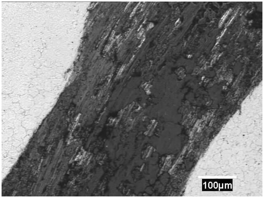
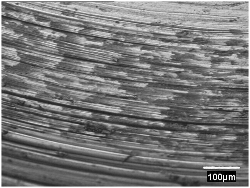
not only reinforces the base material but also improves its thermal conductivity. This is very much in line with the investigations in tribological properties of other types of carbon fiber reinforced composites including the discontinuous fiber reinforced aluminum alloy composites (DFRACs).24,25,28 Since thermal conductivities of the developed composites are higher than that of the pure Stellite specimen, the heat generated during the sliding could be properly dissipated, thus results in improved tribological properties of the developed composites. It is due to the same reason that increasing the content level of the fibers lowers the wear rate of the composites. Enhanced hardness: Although no single definable material property can explain wear behavior, it is believed that the wear resistance of a material is affected by its hardness. In general, increasing the hardness of a material enhances its wear resistance since with the higher hardness the material is less prone to deform plastically.1,30,31 Since the developed composites possess higher hardness than pure Stellite 25, they should be more likely to exhibit higher wear resistance. The composite with more carbon fibers has higher hardness and thereby has higher wear resistance. Reduced abrasive wear: The worn surfaces in Figure 10(a) to (g) demonstrate that the wear tracks of the developed composites are much narrower than that of pure Stellite 25 (up to 51% narrower for composite P). Also, it is observed that the surfaces of the wear tracks in the developed composites are smooth (Figure 10(b) to (g)), while the surface damage of the pure Stellite specimen is more severe with the dominant wear mechanism of ploughing groove as seen in Figure 10(a). The presence of numerous deep and long grooves is more evident in the worn surface of pure Stellite 25, as shown in Figure 11, compared with the smooth wear track of composite P in Figure 12. The debris of these grooves can promote abrasive wear on pure Stellite 25 and its mating surface. Therefore, in light of the much lower wear rates offered by the fibers, it can be concluded that the fibers might have a wear-preventive role by acting as hard barriers to control the size and the shape of the wear fragments in the composites. In addition, no abrasive wear is observed due to the pulled out fiber from the matrix, caused by the mechanical attack during the sliding process. This might be regarded as the strong interface bonding between the matrix and the fibers in the developed composites due to the developed HIP/sintering fabrication technique. Smooth and narrow wear track of the specimen P. Long and deep grooves in the worn surface of the pure Stellite 25 specimen.
Conclusions
A group of nickel-coated carbon fiber reinforced Stellite 25 composites were designed and produced successfully by the hot isostatic pressing routine. The main conclusions from this research may be summarized as follows.
The pure Stellite 25 specimen and all developed composites have a very similar matrix microstructure. The carbide volume fractions in all the specimens are nearly equal, which indicates that the carbon fibers did not diffuse into the alloy matrix to induce any carbide even at the high temperature during the sintering process. The diffusion protection may be attributed to both the high-temperature stability of carbon fibers and the nickel coating.
The developed composites, even the specimen with the highest content of carbon fiber, exhibit better corrosion resistance than medium-carbon Stellite alloys, for example, Stellite 6B. This is attributed to the beneficial feature of carbon fiber that does not induce any carbide in the alloy matrix.
The addition of carbon fibers into the low-carbon Stellite alloy, Stellite 25, enhances its hardness and improves its tribological properties. Both the hardness and wear resistance of the composite increase with the content of carbon fiber added. The mechanisms for the tribological improvement involve the formation of a solid thin graphite film as a lubricant on the mating surface, which lower the friction; the enhancement of thermal conductivity, which promotes the friction heat dissipation; and the reduction of abrasive wear, owing to the excellent resistance to wear of carbon fiber.
Footnotes
Funding
The authors are grateful for the financial support from the Natural Science & Engineering Research Council of Canada (NSERC), in-kind support form NRC Canada, and both financial and in-kind support from Deloro Stellite Group.
Conflict of interest
None declared.