
Abstract
Surface depressions are common defects in the continuous casting process of hypo-peritectic steel, categorised into transverse and longitudinal depressions. While the formation processes of these depressions are well understood, their influence on the propagation of longitudinal surface cracks remains unclear. This study developed a new method for large-area surface depth measurement of the strand based on optical focusing. Utilising this method, we investigated the impact of surface depressions on the three-dimensional propagation of longitudinal surface crack in terms of width, depth and casting direction through macrostructure characteristics and finite element static analysis. The results indicated that transverse and longitudinal depressions affect crack propagation differently. Specifically, the depth of longitudinal depressions increases crack width, while transverse depressions can inhibit it to some extent. Macrostructure analysis of the cross-section revealed a continuous segregation line at the bottom of the depression, closely related to heat transfer, thermal stress, and the flow of solute-enriched liquid steel. Statistical analysis indicated that the depth of longitudinal depressions significantly affects the length of the segregation line, which in turn influences crack depth. However, no surface cracks were found at the bottom of transverse depressions adjacent to longitudinal depressions. This may be due to the banded grains at the bottom of transverse depressions resisting tensile thermal stress parallel to the strand's width direction. Along the casting direction, crack propagation primarily occurs along the bottom of longitudinal depressions due to continuous thermal disturbances at the meniscus. Meanwhile, the transverse depression can restrict the propagation of the existing crack while promoting the formation of the new crack at the other site. Finally, the study proposed mechanisms by which depressions influence the propagation of the longitudinal surface crack. This research further elucidates the impact patterns of surface depressions on macrostructure and stress distribution and how these factors subsequently influence crack propagation in three dimensions. It underscores the importance of controlling surface depressions to mitigate the longitudinal surface crack.
Keywords
Introduction
The longitudinal surface crack is the most prevalent defect in the continuous casting process, particularly for hypo-peritectic steel.1–5 While minor cracks can be removed through flame cleaning, large cracks may lead to scrapped strands, significantly disrupting the smooth progression of steel production and undermining economic benefits. Despite extensive research into the formation mechanisms and defect control,6–9 this defect remains inevitable in practical production. The formation of the longitudinal surface crack involves two stages: initiation and propagation.10–16 It is widely accepted that the longitudinal surface crack arises below the meniscus and propagates in width, depth, and casting direction in the subsequent solidification process, with the latter determining the severity of the crack. Thus, delving into the propagation process of the longitudinal surface crack and the factors influencing it will provide deeper insight into its formation mechanism, which is conducive to the control of this defect.
Previous research on the propagation of the longitudinal surface crack has primarily focused on depth and the casting direction. For the depth propagation, a close correlation is identified with the first brittle zone of steel. Specifically, the solute-enriched liquid steel at the inter-dendritic region extends the interval between zero strength temperature (ZST) and zero ductility temperature (ZDT), thereby promoting crack propagation along the columnar dendrites.16–18 However, for hypo-peritectic steel, the longitudinal surface crack is often accompanied by longitudinal surface depression,1,7,19 with the crack primarily located at the bottom of the depression. Brimacombe's statistics on the crack depth and depressions in cross-sections revealed that the deeper crack is related to the deeper depression. 1 Therefore, the surface depression is significant for the crack propagation in hypo-peritectic steel. Most research has been focused on the formation process of depression. Brimacombe stated that the depression arises from volume shrinkage due to the peritectic transformation. Wolf 4 indicated that irregular factors such as level fluctuation and uneven infiltration of liquid slag may lead to depression and crack. M.S. Zappulla 20 concluded that thermal and mechanical disturbance during initial solidification causes local stress concentration and depression, consistent with previous results by Wolf. 4 Although existing work has provided some understanding of the formation of the surface depression and its relationship with the longitudinal surface crack, the influence mechanism of the surface depression on the propagation of the longitudinal surface crack in the depth direction remains unclear. In addition to local stress concentration, the depression may further influence local heat transfer, affect the solidification macrostructure, and ultimately, the crack propagation behaviour in the depth direction.
Crack propagation along the casting direction represents another critical factor influencing crack severity. Kohno et al. 10 initially analysed the metallographic characteristics of the longitudinal surface crack through cross-sectional slicing along the casting direction. They observed that crack propagation aligned with the area exhibiting element segregation of C, Mn, P and S. Wang et al. 7 quantified surface depression depth according to the sample from the thermal simulation and found that a crack occurs at the bottom of the depression along the casting direction. Meanwhile, Yang 13 utilised the finite element method (FEM) to simulate microcrack propagation under thermal stress, revealing that microcracks tended to propagate perpendicular to the direction of principal stress. The strand surface in the casting direction contains comprehensive information related to the solidification process from the meniscus, such as the longitudinal and transverse depressions, which may influence the crack propagation in the casting direction. However, existing research on the longitudinal surface crack at the macro scale is limited, and there are substantial differences in the formation process of macro-longitudinal surface cracks with varying actual production. 21 Therefore, quantitative analysis of the three-dimensional characteristics of large-area longitudinal crack defects in actual continuous casting production is essential.
In summary, while the formation of depressions and the propagation of longitudinal cracks have been investigated, most research focuses separately on either depressions or cracks. In reality, depressions can cause stress concentration and affect local heat transfer, ultimately influencing crack propagation. However, the lack of a comprehensive method for characterising surface depression over a large area restricts the investigation into the influence of transverse and longitudinal depressions on the longitudinal surface crack, particularly in the casting direction. This work aims to examine the effect of surface depression on the propagation mechanism of the longitudinal surface crack in three dimensions: width, depth, and casting direction, using actual large-area defect samples of hypo-peritectic steel. Firstly, a novel method based on optical focusing is developed to quantitatively characterise surface depressions over a large area. Subsequently, the segregation characteristics of crack cross-section are analysed across slices obtained from different positions, examining the influence of longitudinal depression depth on carbon macro-segregation and crack depth. FEM models are then constructed to investigate the impact of transverse and longitudinal depressions on the propagation of the longitudinal surface crack in the casting direction. Finally, the influence mechanism of surface depressions on the longitudinal surface crack in both the depth and casting directions is proposed, providing theoretical guidance for the effective control of the longitudinal surface crack by inhibiting their propagation.
Methods
Defect samples were selected from the inner web position of hypo-peritectic steel beam blanks during actual production. The dimension of the beam blank is 730 mm in length, 370 mm in width and 90 mm in web thickness. A constant casting speed of 0.8 m/min was adopted during the casting process, and the steel compositions are detailed in Table 1. Due to the complexity of the cross-section of beam blank in actual production, the conditions for online defect monitoring, such as the mould thermocouple monitoring are not available. Thus, defective products were all identified through surface quality inspection after the strands had cooled to room temperature. Through on-site tracking for a large number of defective strands, three typical categories of samples with longitudinal surface cracks were identified: tortuous type (No.1), straight type (No.2) and cracks with deep transverse depression (No.3). The macro-morphology graphs of these samples are illustrated in Figure 1. The depth of depression at various positions on each sample's surface was measured using the developed method. This depression depth was then correlated with the crack morphology to facilitate a comprehensive analysis of the relationship between the longitudinal surface crack and depression. Subsequently, local typical samples were obtained through wire cutting. Nitric acid alcohol etchant was used to reveal the macrostructure of the initial solidification shell, allowing for subsequent analysis of energy dispersive scanning (EDS) and macrostructure characteristics. Furthermore, crack formation is closely related to the stress distribution during the initial solidification process within the mould. Therefore, Abaqus was used to calculate the stress distribution of the initial solidification shell with surface depressions.
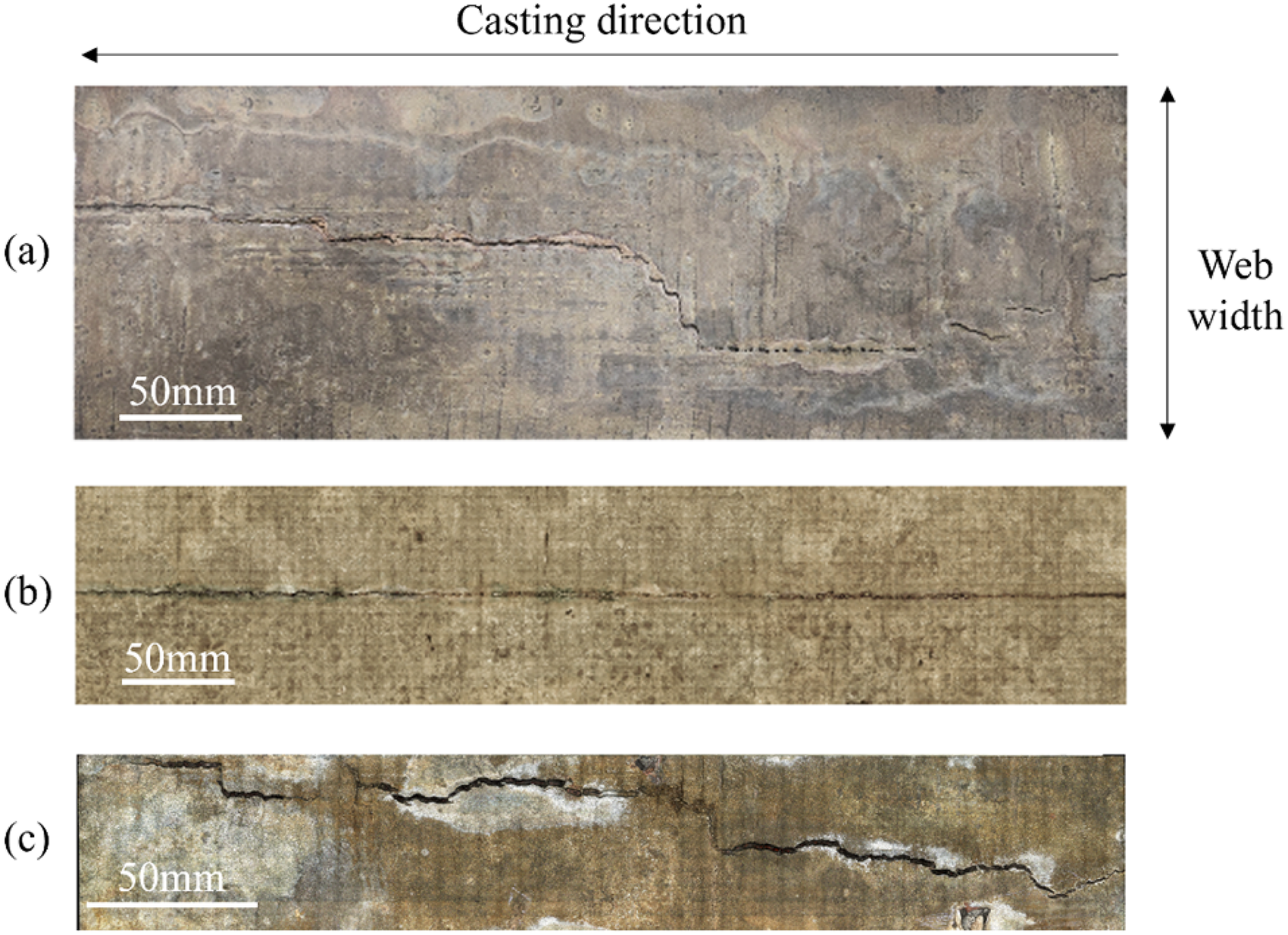
Macro-morphology of three typical crack samples with (a) tortuous cracks (sample No.1), (b) straight cracks (sample No.2) and (c) the deep transverse depression (sample No.3).
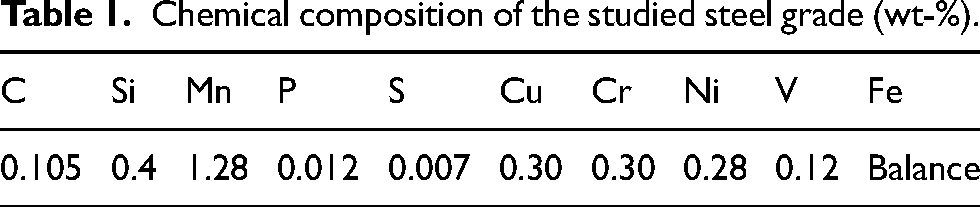
Chemical composition of the studied steel grade (wt-%).
Surface depth measurement of large-area strand
Numerous methods exist for measuring surface roughness or depth with high accuracy, even achieving precision down to the nanometer scale. 22 However, these methods often lack efficiency when measuring samples with large surface areas, such as the strand. In this study, an optical focusing method 23 was developed to measure the surface depth of large-area strands, as depicted in Figure 2(a). This method includes two parts: the device module and the software module. The device module obtains the absolute height of the strand surface, while the software module executes zero calibration and detrending to acquire the relative height value and eliminates sample inclination induced by the cutting process. Specifically, within the device module, the sample table can move along the x-axis and y-axis, allowing a single sample to be subdivided into multiple micro-regions. In each micro-region, the camera automatically performs optical focusing by adjusting the distance between the camera and the sample, determining the height Z corresponding to the optimal image clarity as the absolute height of the current micro-region. To balance measurement accuracy and efficiency, the length of each micro-region along the casting direction was set to 6 mm and the width to 3 mm. This method captures both the depth of surface depressions and the macro-morphology of the sample, allowing the extraction of the surface crack and the generation of a heatmap of depression with the crack. Consequently, the relationship between the surface depression and the longitudinal surface crack can be further analysed. Figure 2(b) compares results obtained by manual and automatic measurement. The relative error between results obtained by this method and the actual value is +3.60%, indicating the method's accuracy in measuring depression depth. Meanwhile, the depth for the depression obtained using this method is sufficiently accurate, achieving a precision of up to 50 μm.
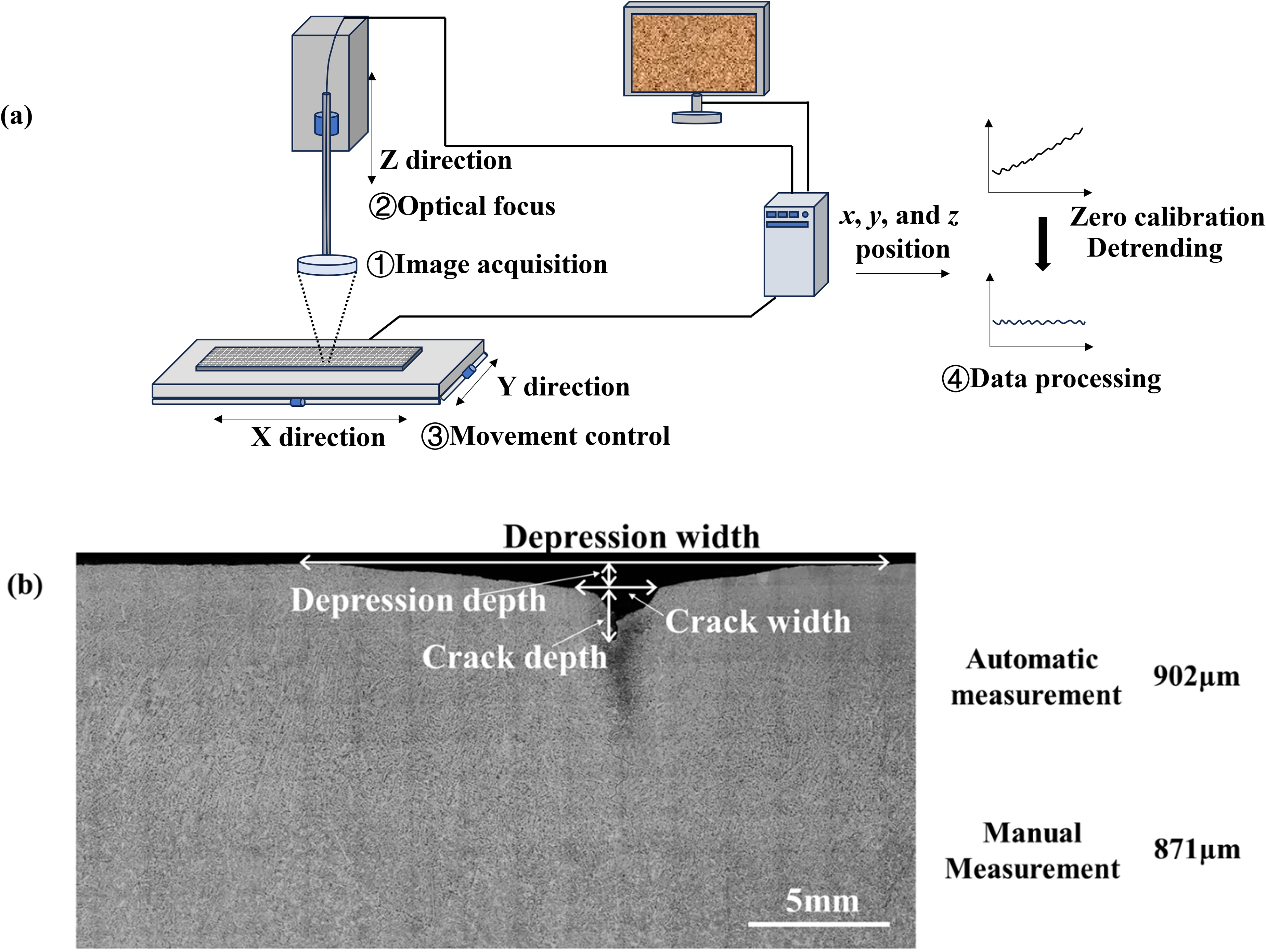
Schematic diagram (a) of large-area surface depth measurement for continuous casting strands and (b) results comparison between automatic and manual measurements.
Acquisition and composition analysis of macrostructure
From the three large longitudinal crack specimens, 12 typical subsamples (15 mm × 30 mm) were cut for detailed analysis of macrostructure characteristics and carbon content, which included 2 transverse depression specimens (free of cracks) and 10 longitudinal depression specimens (with cracks). Due to the low-carbon content, the conventional hot pickling method with hydrochloric acid often results in over-corrosion and uneven etching for low-carbon steel. Although picric acid efficiently reveals macrostructure, it has been gradually deprecated due to its susceptibility to explosion. A 4% nitric acid alcohol solution is commonly used to reveal the metallography of carbon steel. This work found that it effectively and uniformly corrodes the macrostructure of low-carbon steel, avoiding misjudgement between segregation and cracks. Consequently, a 4% nitric acid alcohol solution was used to etch the macrostructure after grinding and polishing. By utilising the automatic movement of the sample table in Section ‘Surface depth measurement of large-area strand’, we can obtain large-area metallographic images of samples by the improved conventional camera. Subsequently, the EDS was employed to determine the solute element content in the local area and explore the effect of surface depressions on solute element segregation. During energy spectrum scanning, consistent scanning durations were maintained for each sample to ensure effective composition comparison across different samples.
Stress analysis of solidification shell
The thermal stress plays a pivotal role in crack formation during initial solidification. Surface depression occurs when the weak point of the shell first reaches the yield strength at the high temperature of the steel due to stress concentration. Meanwhile, the formation of depression exacerbates stress concentration at the depression position, which easily leads to crack propagation. Therefore, a static model of structural mechanics is employed to describe the stress distribution of the initial solidification shell under thermal stress for the sample with surface depression. The governing equations include the motion equation, strain–displacement equations, and constitutive equations, as shown in Equations (1), (2) and (3), respectively.
24


Simultaneously, Young's modulus and Poisson's ratio of steel with an approximate carbon content at 1250 °C were selected, measuring 3.07 GPa and 0.37, respectively. 25 The model's geometry and boundary conditions are illustrated in Figure 3. The web area measures 100 mm × 150 mm, with a shell thickness of 10 mm to simulate actual initial solidification conditions within the mould. Additionally, stress applied in the casting and width directions amounts to 3.56 MPa and 6.45 MPa, respectively. 13 Grooves with dimensions corresponding to the actual transverse and longitudinal depressions are incorporated into the model geometry to investigate the effect of depressions on stress distribution.
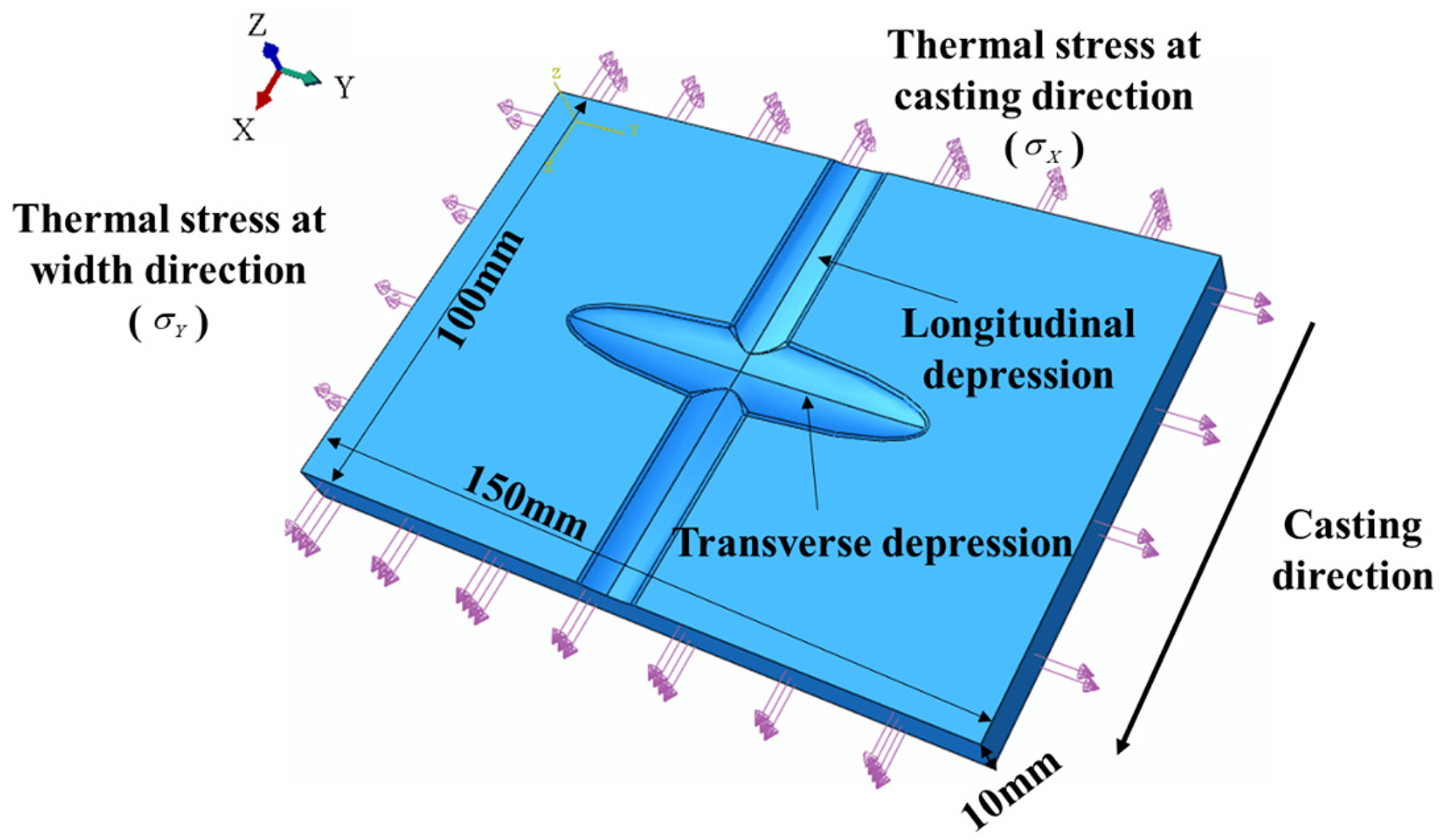
Model geometry and boundary conditions.
Results and discussion
The effect of depressions on crack width
Tortuous longitudinal surface crack
The heatmap of depression depth for sample No.1 with tortuous longitudinal surface crack, is shown in Figure 4, measured using the developed method. The results indicate that the depression at different positions on the surface is consistent with the actual situation. The crack swings along the casting direction within the web width. Notably, a clear correlation exists between the crack and the depression. Additionally, two wide transverse depressions are evident at the main crack's tail. Tiny cracks appear on either side of the transverse depression along the casting direction, deviating from the original longitudinal crack's position. Remarkably, no distinct surface cracks were observed at the deepest sites of the transverse depressions.
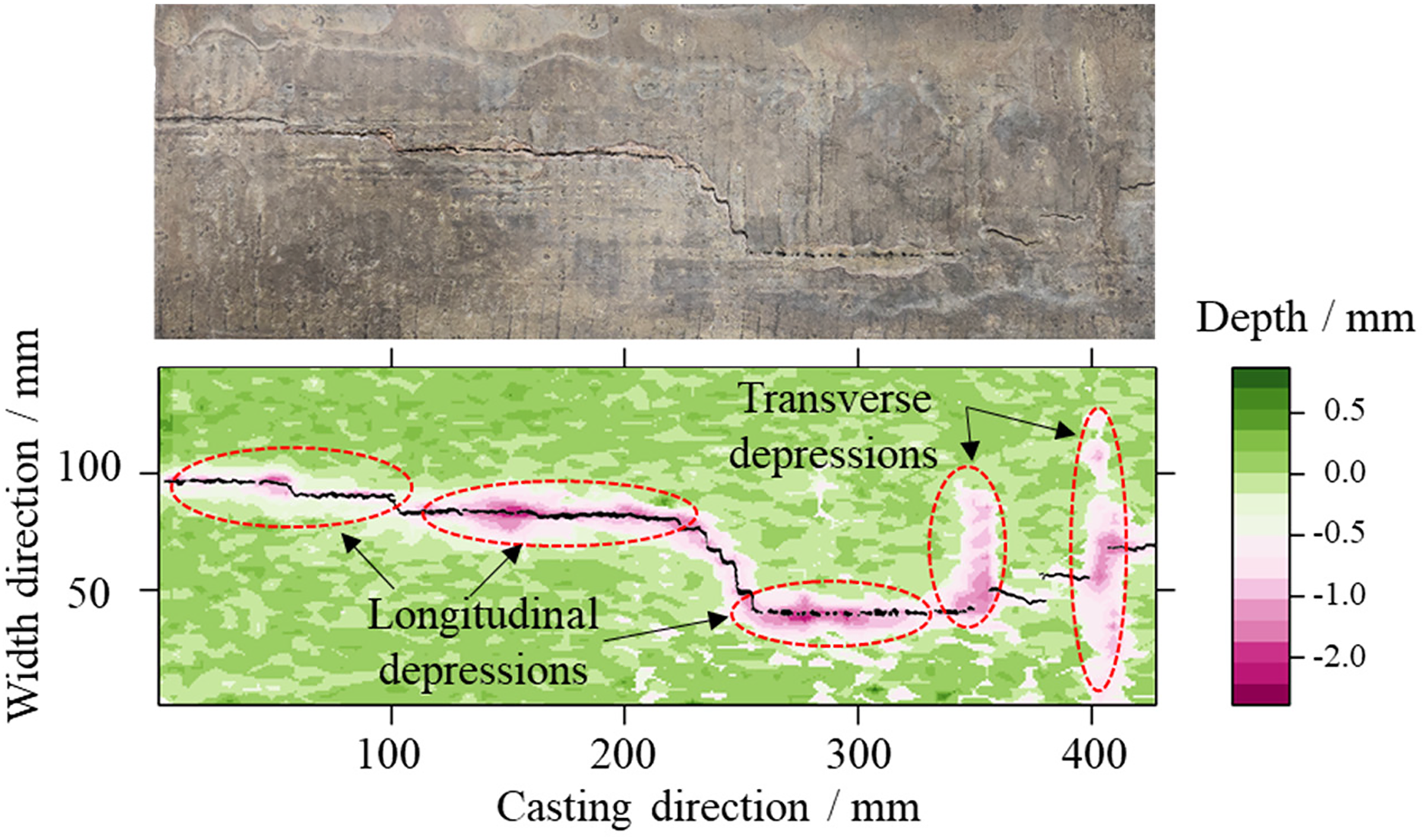
Heatmap of depression depth for sample No.1.
Straight longitudinal surface crack
Figure 5 illustrates the heatmap of depression depth for sample No.2 with straight longitudinal surface crack. The crack closely aligns with the longitudinal depression. While the longitudinal crack may exhibit a slight shift within the web width direction, its propagation generally parallels the casting direction. Similar to sample No.1, transverse depressions are present at certain positions, with no surface crack observed at these locations.

Heatmap of depression depth for sample No.2.
Longitudinal surface crack with deep transverse depression
Figure 6 displays the heatmap of depression depth distribution for the sample No. 3, which has a deep transverse depression. This sample notably differs from the first two in that it exhibits a deeper transverse depression near the midpoint along the casting direction, accompanied by a short longitudinal depression on both sides of the transverse depression. As the crack propagates along the longitudinal depression, it subsequently swings in the width direction of the sample. Further inspection of the sample surface revealed molten steel overflow along the oscillation mark at the deepest part of the transverse depression. This suggests that a transverse crack likely formed at this position during the early stages of the solidification process, potentially due to inadequate lubrication between the copper plate and shell surface.
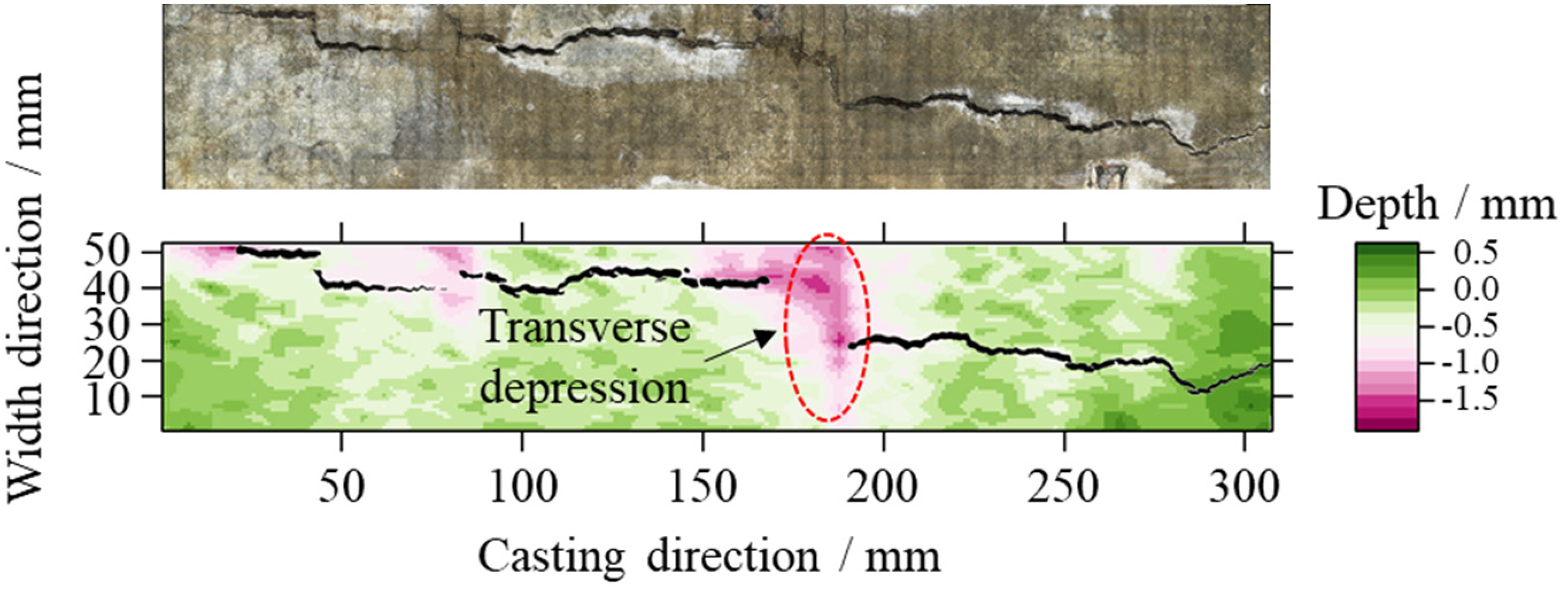
Heatmap of depression depth for sample No.3.
Through analysing the macrostructure of depressions and cracks, values for crack width, depression depth, and depression width at various positions along the casting direction can be extracted. Crack width is directly measured by the width of the black area in Figures 4 to 6. Depression depth is defined as the deepest depression value in the width direction at each position along the casting direction. Since the surface height has been zeroed, meaning the average height of the normal area (non-depression area) is set to 0, the surface depth in the depression regions is below 0 mm. Therefore, the depression width can be defined as the interval along the slab width direction where the surface depth is less than 0 mm. The extracted results are illustrated in Figure 7. These results reveal fluctuating characteristics in crack width along the casting direction, with variations increasing or decreasing during the casting process. This suggests that the longitudinal surface crack may initiate at multiple locations and eventually form a continuous crack during propagation.
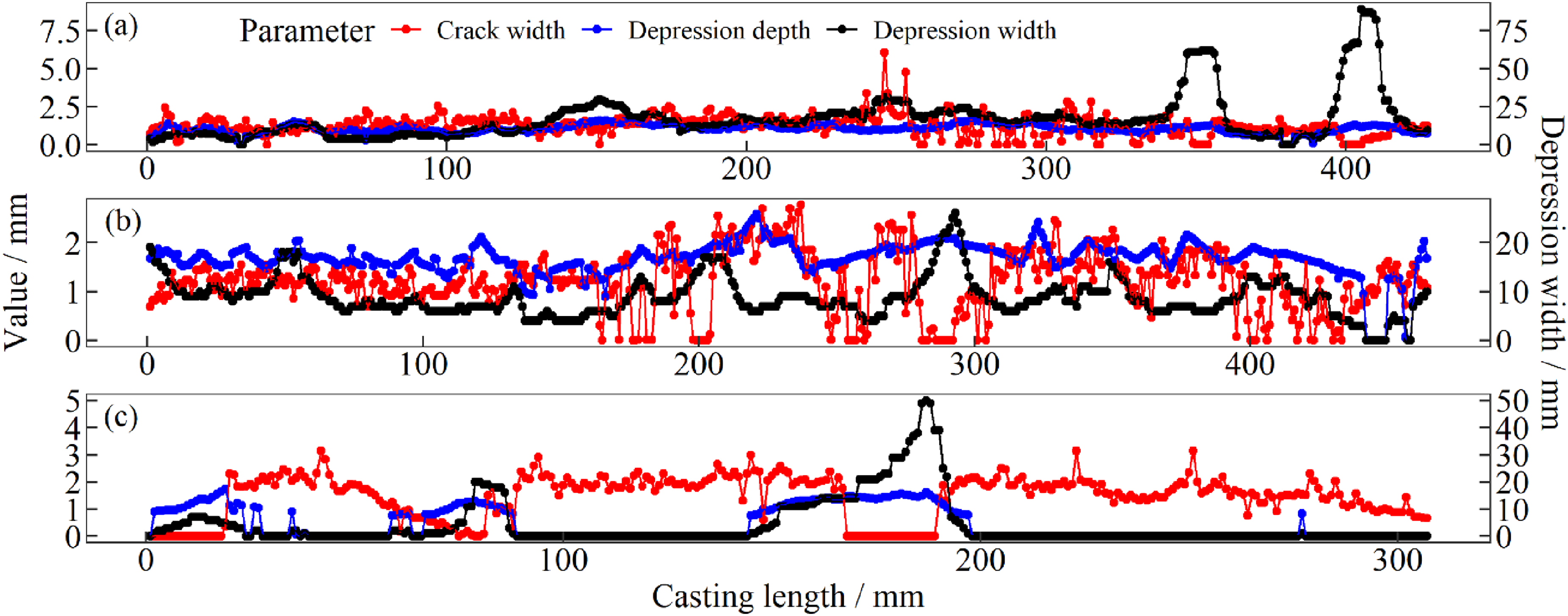
Variation in crack width, depression depth, and depression width along the casting direction for samples (a) No.1, (b) No.2 and (c) No.3.
Next, the statistical relationship between depression depth, depression width, and crack width at different positions was analysed. To better understand the influence of different depressions on crack propagation, transverse and longitudinal depressions were categorised based on their width. Depressions wider than 20 mm were classified as transverse depressions, while those narrower than 20 mm were classified as longitudinal depressions. Figure 8 illustrates how depression depth varies with depression width. The results indicate that for all samples, depression depth increases with width. When the depression is narrow, the depth increases rapidly; when the depression is wide, particularly for the transverse depression, the depth increases slightly, which can be attributed to the thermal stress and yield strength of steel at high temperature. This suggests that reducing depression width may mitigate depression depth to some extent, and the influence mechanisms for transverse and longitudinal depressions on crack formation may be different.
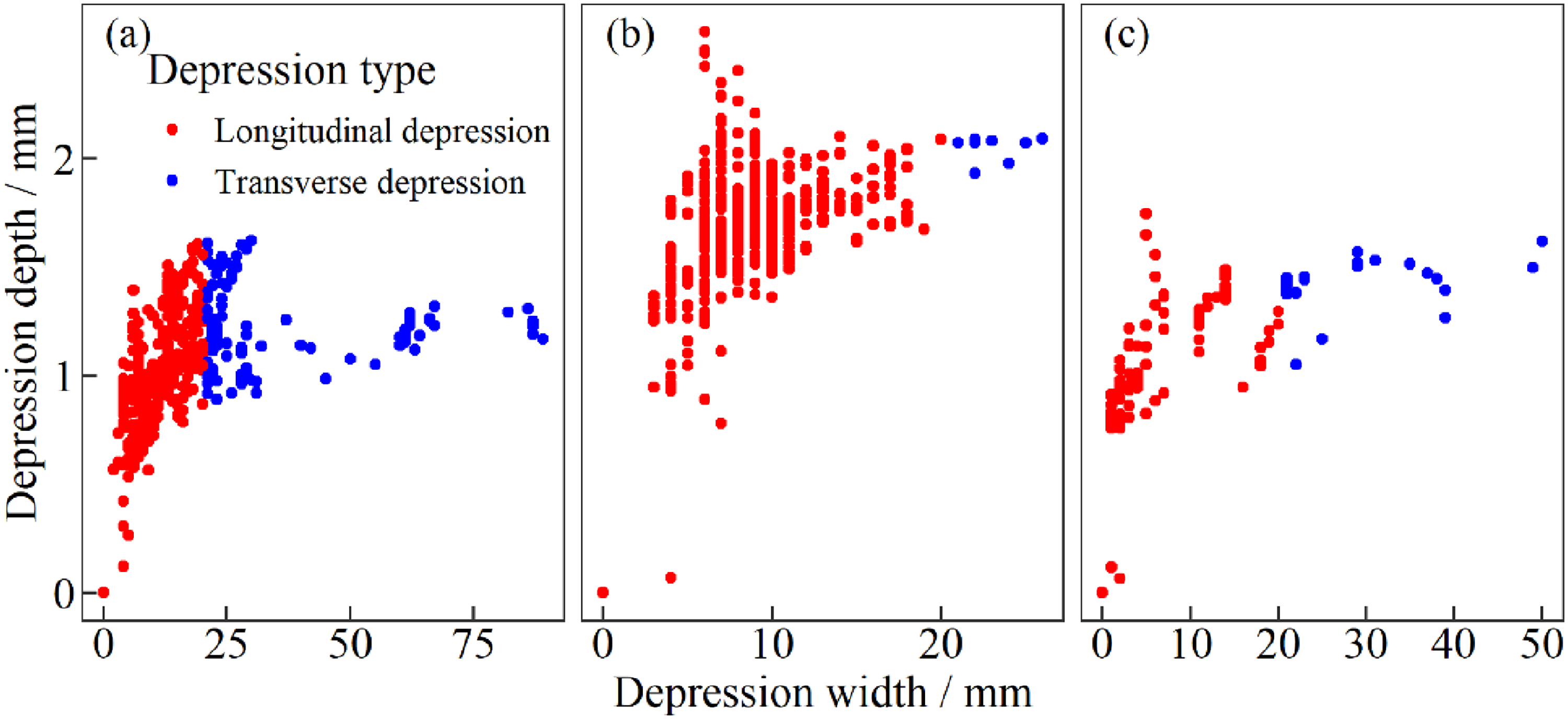
Relationship between width and depth of surface depression for samples (a) No.1, (b) No.2 and (c) No.3.
Figure 9 illustrates the relationship between crack width and depression depth obtained through linear fitting. For samples No.1 and No.2, the crack width gradually increases with depression depth. In contrast, Figure 9(c) shows an opposite trend for sample No.3, likely due to the fewer longitudinal depressions. Notably, the depression depth at most positions for sample No.3 is around 0 mm, which may introduce statistical errors in the linear fitting. Additionally, for cracks near transverse depressions, the crack depth gradually decreases with increasing depth of transverse depression. This suggests that positions closer to the bottom of transverse depressions are less prone to surface crack. Therefore, the influence mechanisms of transverse and longitudinal depressions on the propagation of longitudinal cracks in depth and casting direction will be further discussed in sections ‘The effect of depressions on the propagation of crack in the depth direction’ and ‘The effect of depressions on the crack propagation in the casting direction’.
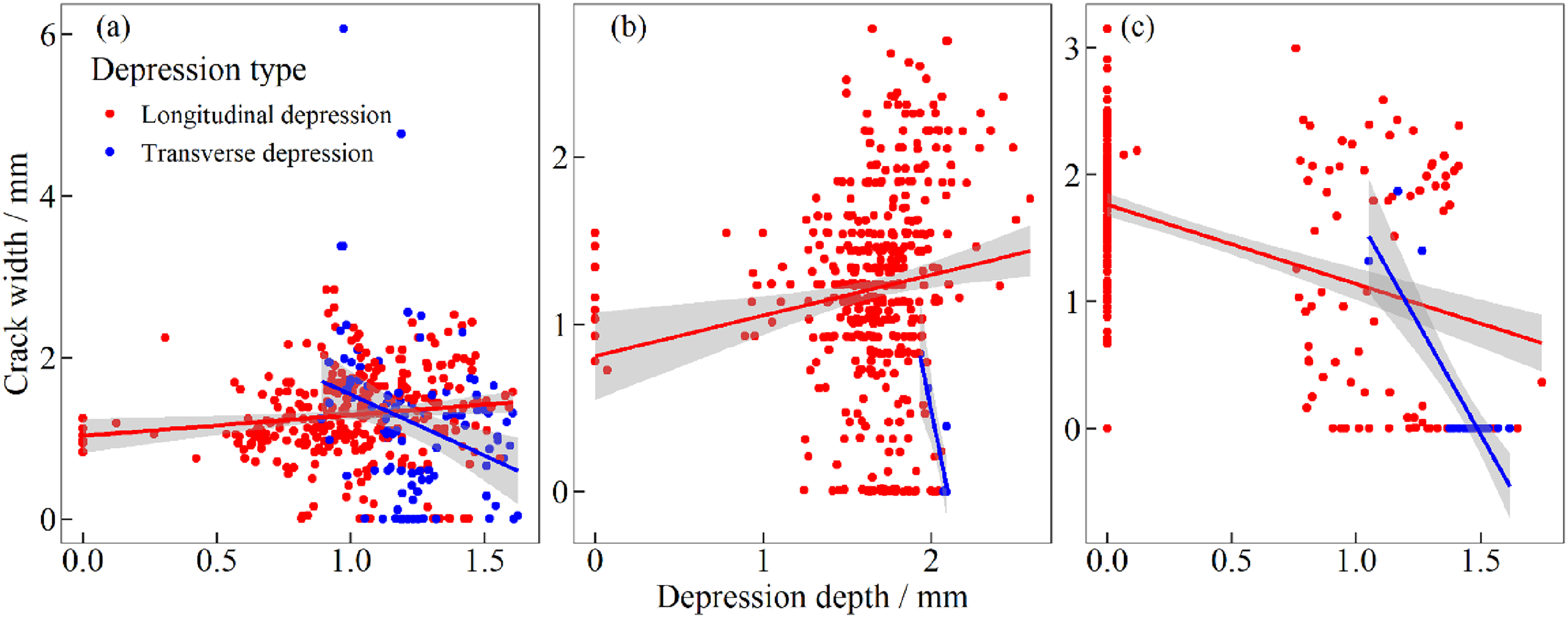
Relationship between depression depth and crack width for samples (a) No.1, (b) No.2 and (c) No.3.
The effect of depressions on the propagation of crack in the depth direction
The crack depth is crucial for assessing crack severity. This study selected representative slices from samples for macrostructural analysis to investigate propagation mechanism in the depth direction. Figure 10 compares the metallography between crack samples without (from sample No.3) and with depression (from sample No.1). The steel matrix exhibits white and black areas, corresponding to ferrite and pearlite, respectively. Discontinuous cracks in the depth direction are observed in the sample without depression. Additionally, subsurface cracks along columnar dendrites are also present. In contrast, for the sample with depressions, the crack extends inward for a considerable distance. Near the crack bottom, visible coarse crystals demonstrate equiaxed growth, suggesting that the formation of depression reduces cooling intensity in the local area and diminishes the temperature gradient. 26 Furthermore, a continuous black line exists between coarse crystals, with its top position generally coinciding with the crack bottom, indicating that the formation of depression may promote the generation of an internal continuous black line. Further analysis will explore the influence of depression on the black line and its relationship with crack depth.
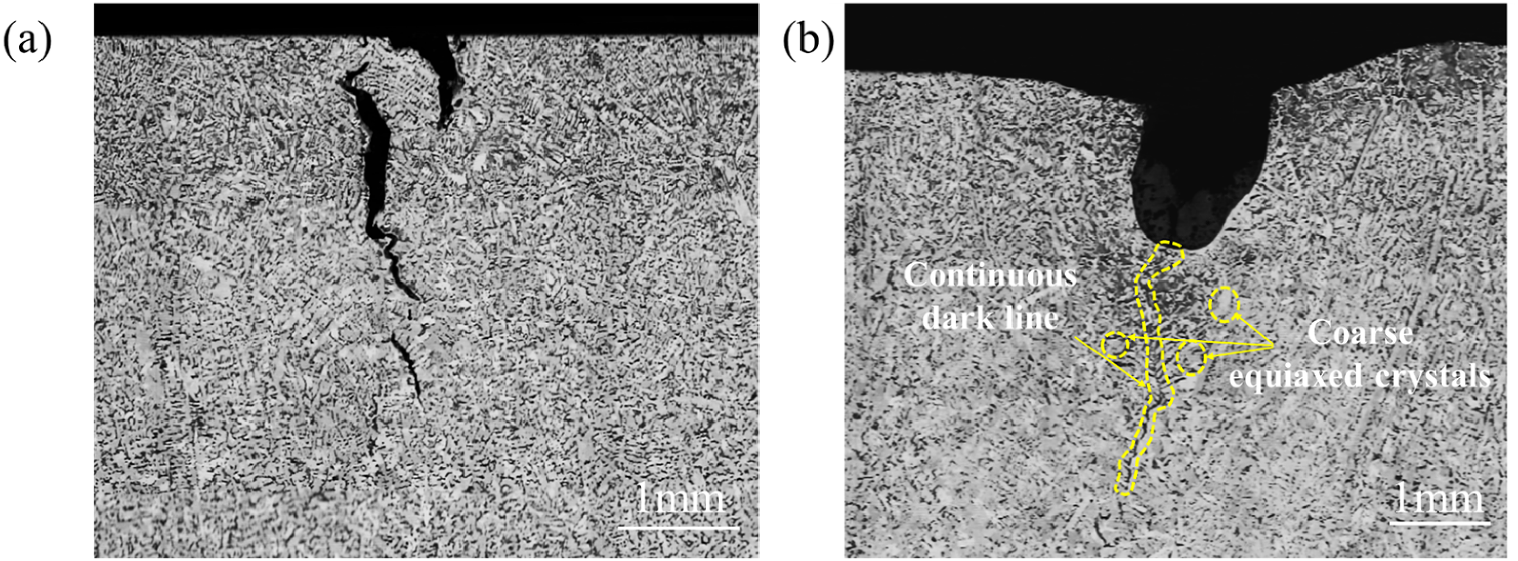
Comparison of macrostructures between crack samples (a) without and (b) with depression.
Based on the corrosion mechanism of nital on carbon steel, areas with carbide enrichment or carbon segregation are typically the first to be corroded. Consequently, these areas exhibit greater depths and appear darker under an optical microscope. Initially, EDS was employed to scan the carbon composition over a length of approximately 2 mm on both sides of the black line at a depth of 1.5 mm from the crack bottom. The results along the scanning lines are depicted in Figure 11. It can be seen that proximity to the black line correlates with higher carbon content, peaking at the black line's position. This demonstrate that the black line at the crack's bottom is indeed a carbon-rich area, exhibiting macro-segregation of carbon, which is similar to the phenomenon observed under the bottom of oscillation marks in the other strand. 27 Macro-segregation is closely associated with molten steel flow within the mushy zone. 28 The results indicate that factors such as thermal or mechanical disturbances induce depressions at specific positions on the solidified shell, restricting the cooling rate and temperature gradient and promoting relatively coarse equiaxed crystals. Additionally, molten steel enriched with solutes lowers the solidus temperature and may cause solidified dendrites to remelt. 29 Concurrently, tensile thermal stress generates a negative pressure area at the bottom of the depression 30 leading to the flow of enriched solute liquid steel at the depression's bottom. Eventually, a continuous solute-rich liquid film forms between coarse crystals, which is difficult to solidify due to the high carbon (C) and sulphur (S) content in the region. Consequently, cracks easily propagate along this segregation line. A detailed explanation of the depression formation process is provided in Section ‘Influence mechanism of surface depression on longitudinal crack propagation’ according to macrostructure characteristics of typical samples.
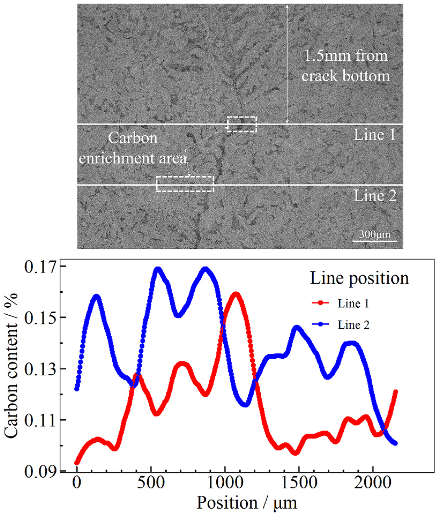
Distribution of carbon content near the segregation line at the crack bottom.
To further elucidate the influence of longitudinal depression depth on the formation of segregation lines, the C content near the segregation line was measured across multiple slices. The maximum C content along the line was used as an indicator of segregation severity. A total of 6 samples and 12 scanning lines were analysed, and the average of the maximum content for each sample was calculated. A positive correlation can be observed between the maximum C content and depression depth, as shown in Figure 12(a). Additionally, analysis of more samples found that the deeper depression is often associated with the longer segregation line, as shown in Figure 12(b). Therefore, the depression affects the solute enrichment along the segregation lines and their length, which may ultimately promote the propagation of cracks in the depth direction.
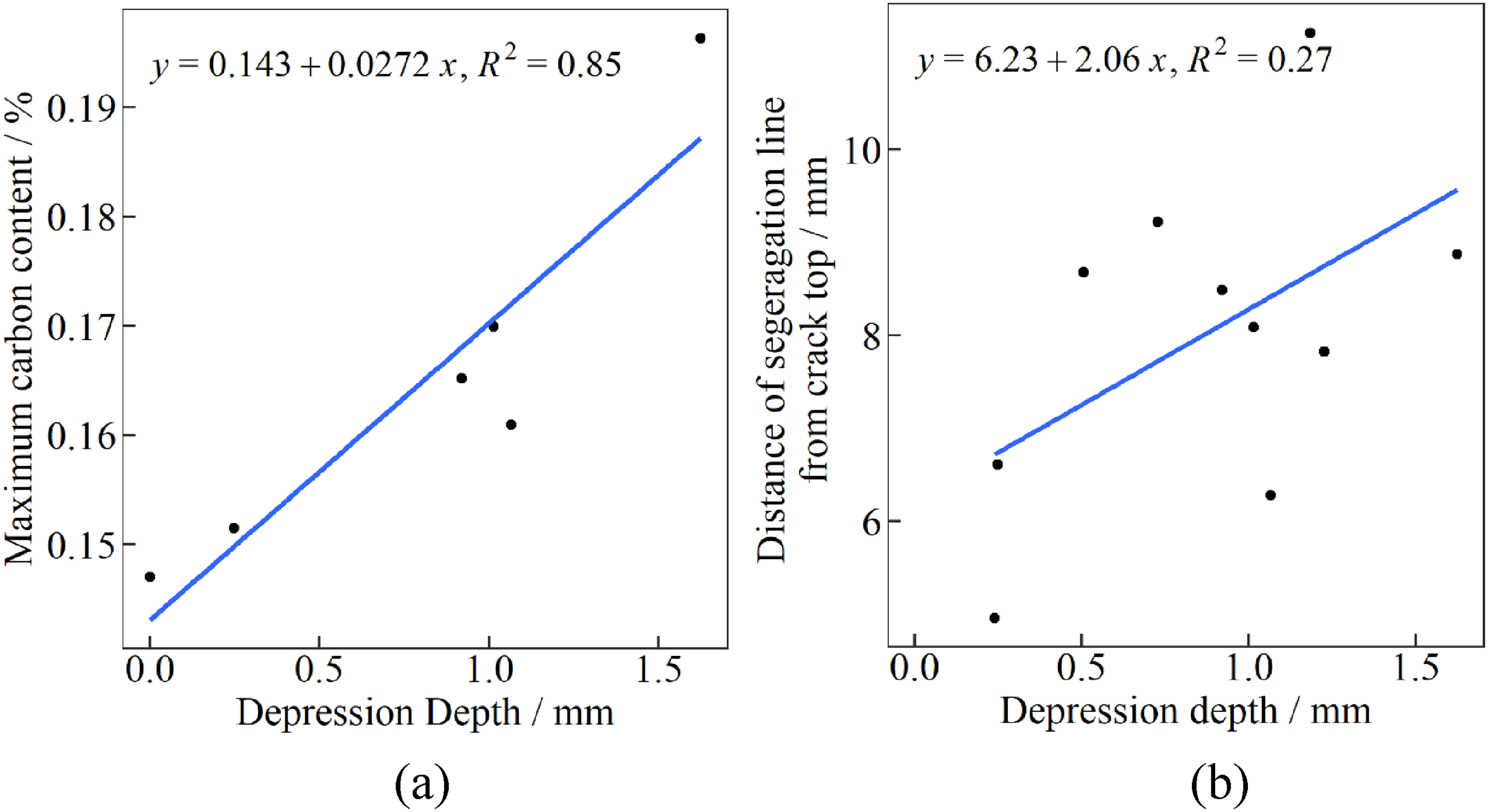
Relationship between depression depth and (a) maximum carbon content at a depth of 1.5 mm from the crack bottom and (b) distance of segregation line from crack top.
The influence of the segregation line on crack depth and width was further analysed, as shown in Figure 13. Similarly, the linear fitting is used to describe the overall trend of the effect of segregation line length on crack propagation. The results indicate that both crack width and depth increase with the length of the segregation line and satisfy the equations
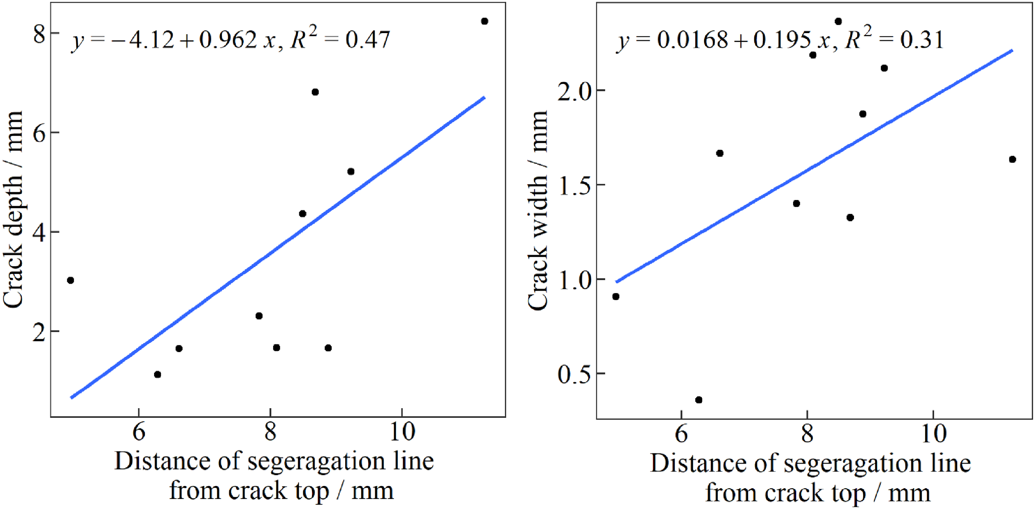
Relationship between the distance from the bottom of the segregation line to the crack top and (a) crack depth and (b) crack width.
For the transverse depression, results differed from those at the longitudinal depression locations. The macrostructure of the cross-section at the bottom of the transverse depression is shown in Figure 14. Despite the severity of the transverse depression, no apparent surface cracks were present. Meanwhile, banded crystals parallel to the sample width direction can be found, suggesting significant plastic deformation during initial solidification. This deformation could be attributed to the extrusion of the slag rim on the primary shell when there is level fluctuation.31,32 Additionally, carbon enrichment is observable at the bottom of the depression, likely resulting from shell plastic deformation due to the extrusion of the slag rim. Subsequently, a negative pressure area forms in the inter-dendritic liquid phase under tensile stress, leading to a continuous segregation line. This behaviour is consistent with the effect of the longitudinal depression discussed earlier. This suggests that banded dendrites parallel to the width direction may increase the high-temperature strength in the width direction.
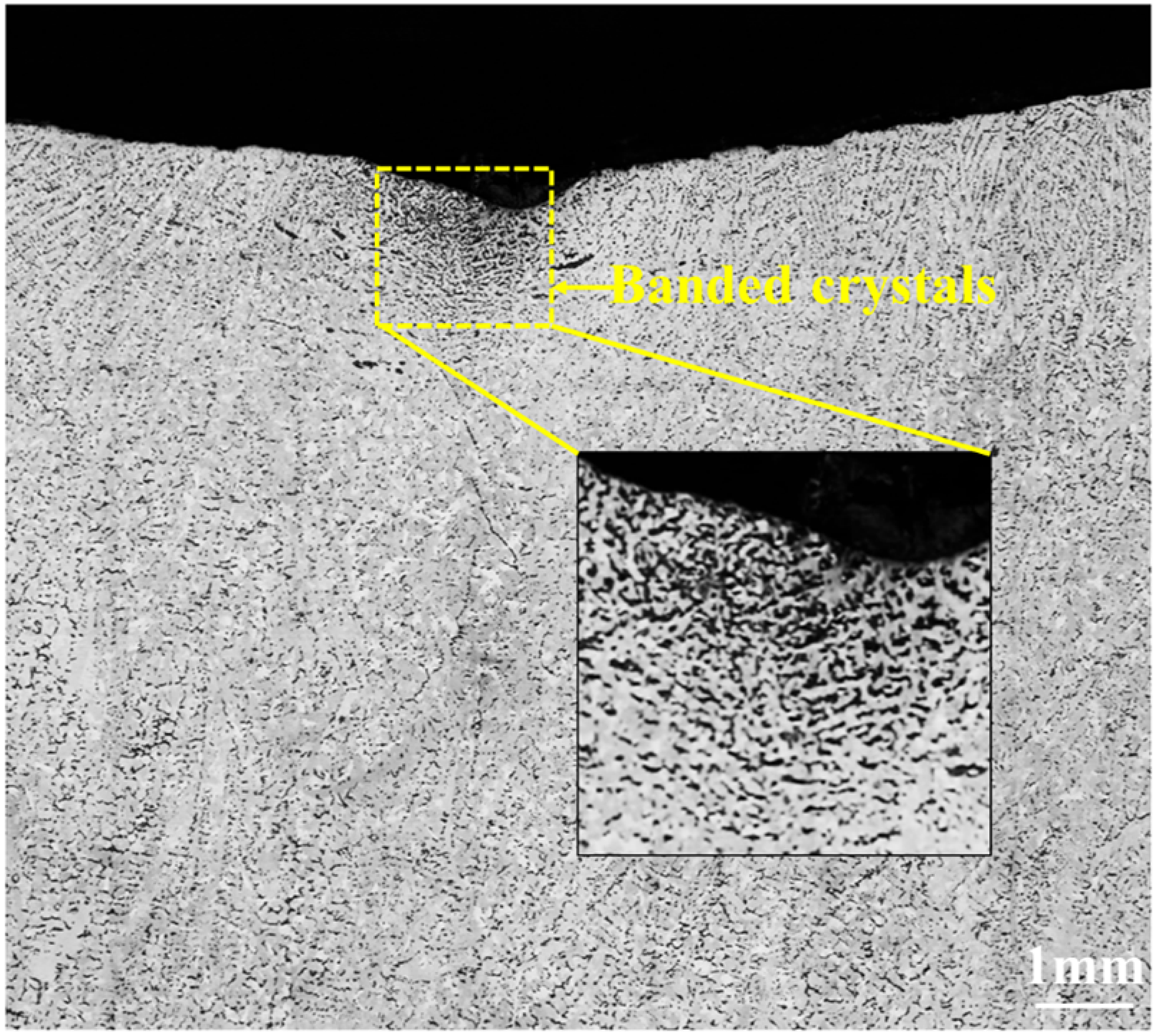
The banded structure at the bottom of the transverse depression.
Although transverse depression is commonly associated with stress concentration at the depression position, stress distribution may be different when the transverse depression and longitudinal depression appear on the strand simultaneously. Thus, the influence of longitudinal and transverse depressions on longitudinal crack propagation in the casting direction will be investigated from the perspective of stress distribution in the next part.
The effect of depressions on the crack propagation in the casting direction
The crack propagation in the casting direction is another crucial factor influencing the severity of the longitudinal surface crack. Continuous longitudinal depression primarily contributes to crack propagation in the casting direction. However, it is noteworthy that the crack in sample No.3 terminates at the left side of transverse depression. Interestingly, a new crack emerged on the right side of the transverse depression at the other position along the width direction, as shown in Figure 6. This indicates that while the transverse depression may hinder the continuous propagation of the original crack, it can also induce the formation of a new crack due to position change of thermal disturbance. Hence, the influence of the longitudinal and transverse depressions on crack propagation in the casting direction was further analysed with the finite element static model.
Referring to the actual local surface depth of sample No.2 (Figure 15(a)), the stress state of the depression area on the initial solidified shell's surface under thermal stress is simulated, as shown in Figure 15(b). The simulation reveals that stress is highest at the bottom of the longitudinal surface depression, which explains why cracks tend to propagate along the longitudinal depression in the casting direction. More importantly, the emergence of a transverse depression significantly alters the stress distribution. Along the casting direction, the stress near the bottom of the transverse depression is approximately 1 MPa lower than that at the top area. Additionally, the sectional stress distribution in Figure 15(c) shows that stress concentration at the depression is predominantly localised within a 2-mm area near the surface, with a more uniform stress distribution in the other subsurface area. Notably, the closer to the bottom of the depression, the lower the degree of stress concentration. In summary, considering the actual macrostructure at the bottom of the transverse depression, it is reasonable to infer that the formation of the transverse depression alters the stress distribution of the original longitudinal depression. Furthermore, the orientation of the dendrites at the depression's bottom aligns nearly parallel to the slab width, effectively hindering the propagation of cracks at the transverse depression.
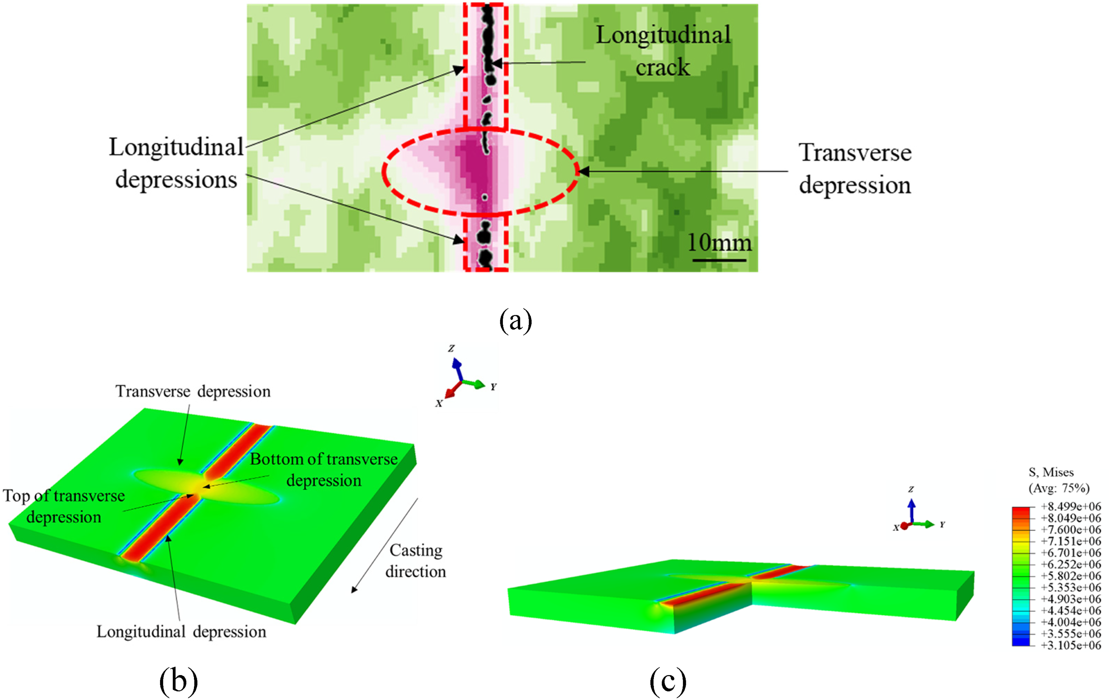
Effect of the transverse depression on the longitudinal surface crack for (a) local region of sample No.2, simulated stress distribution at (b) surface and (c) subsurface.
Although transverse depressions can hinder the continuous propagation of longitudinal cracks, the depth distribution of surface depression for sample No.1 reveals that the transverse depression can also generate small longitudinal depressions on both sides. This phenomenon could be attributed to the local uneven infiltration of liquid slag. Based on this, the stress distribution at the depression position under various conditions of transverse depression depth has been simulated, as illustrated in Figure 16. It can be seen that stress concentration is evident at the position of small longitudinal depressions under thermal tensile stress, suggesting that tiny longitudinal depressions caused by transverse depressions are likely to induce new cracks. Furthermore, stress at both the longitudinal and transverse depressions increases with the depth of transverse depression. This indicates that intense transverse depression can also promote the formation of the transverse crack.
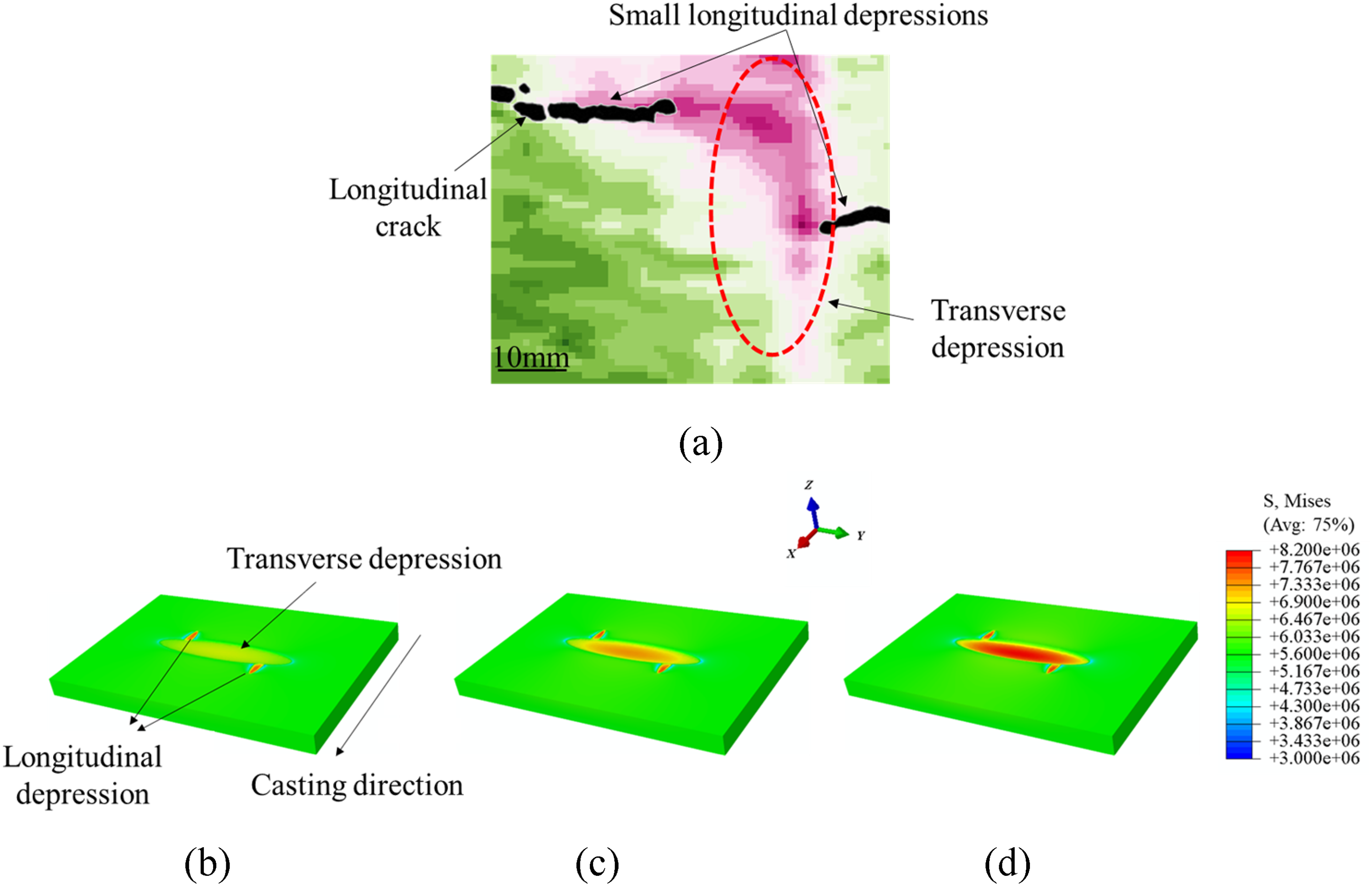
Effect of the transverse depression on the longitudinal surface crack for (a) local region of sample No.3, simulated stress distribution on the shell surface under different transverse depths of (b) 1 mm, (c) 1.5 mm and (d) 2 mm.
Influence mechanism of surface depression on longitudinal crack propagation
The research above highlights the influence of surface depressions on longitudinal crack propagation in three dimensions, emphasising the importance of controlling surface depression formation to effectively prevent the longitudinal surface crack. Previous research 20 suggests that depression formation primarily arises from thermal or mechanical disturbances within the mould. Thus, different characteristics of solidification macrostructure were analysed according to the sample slices. Specifically, the thickness of the chill zone was measured both far from the crack (∼15 mm) and near it, along with primary dendrite arm spacing (PDAS) on the surface and secondary dendrite arm spacing (SDAS) at a certain distance from the surface (8 mm) near the segregation line, as shown in Figure 17. There are significant statistics differences (p value < 0.05) in macrostructure characteristics between the region far away from and adjacent to the crack. Compared to positions distant from the crack, the chill zone near the crack is thinner, PDAS is smaller, and the internal SDAS is larger. PDAS mainly correlates with cooling rate, 33 which can arise from direct contact between molten steel and the copper plate at the meniscus. Rapid cooling causes substantial volume shrinkage and subsequent air gap for hypo-peritectic steel. 34 Then, a reduced local cooling rate results in directional heat transfer and a thinner chill zone due to the initial gap. Additionally, as the necking effect leads to further deepening of the depression, the SDAS in the internal area near the crack will also increase due to the reduction in cooling rate.
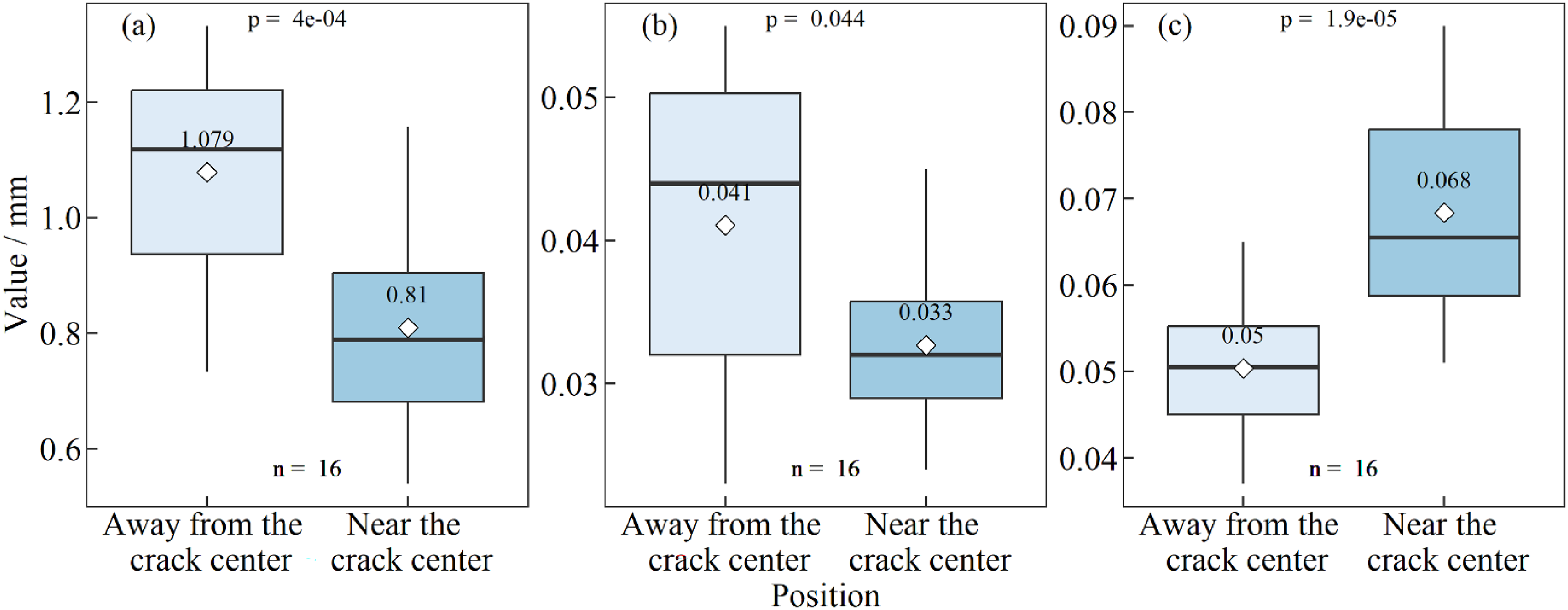
Comparison of microstructure characteristics: (a) thickness of the chill zone, (b) PDAS at surface and (c) SDAS at a depth of 8 mm from the surface between locations away from and near the crack (excluding the sample No.3).
From Figure 6, most areas do not exhibit apparent longitudinal depressions for sample No.3. Therefore, a comparison of macrostructure characteristics between positions far away and near the crack was conducted, as depicted in Figure 18. The results show no significant statistical differences in chill zone thickness, PDAS and SDAS between positions far away and near the crack. This suggests nearly identical cooling conditions during the initial solidification process at both defect and normal positions, revealing similar initial cooling conditions across a broad area for sample No.3. However, compared to other samples (as depicted in Figure 17(a) and (b)), the No.3 sample exhibits a thinner chill zone and smaller PDAS near the crack. This indicates that after the formation of the transverse depression, the infiltration of liquid slag near the meniscus was inadequate, resulting in stronger cooling of the shell at the meniscus. 35 Under such conditions, local longitudinal depressions do not form since the area of thermal disturbance is sufficiently wide. However, intense cooling can cause severe inter-dendritic segregation, 36 thus leading to subsurface cracks, as shown in Figure 19. Subsequently, the location of the subsurface crack becomes less stable than the crack arising from the depression. Although the resultant continuous surface crack generally aligns parallel to the casting direction, the crack is more sinuous in the width direction, as depicted in Figure 6. This may be because cracks on the surface of the solidification shell always propagate along the austenite grain boundaries, mainly due to the higher stress concentration at the grain boundaries. 37
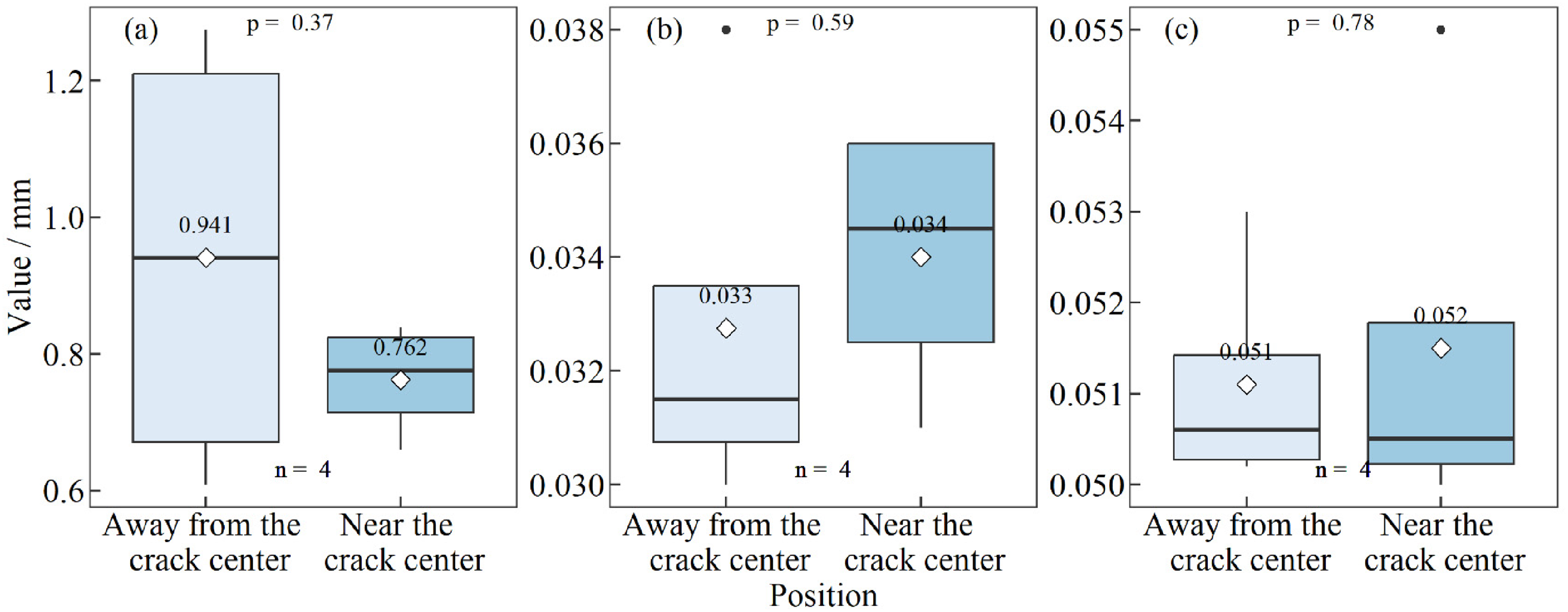
Comparison of microstructure characteristics: (a) thickness of the chill zone, (b) PDAS at surface and (c) SDAS at a depth of 8 mm from the surface between locations away from and near the crack for sample No.3.
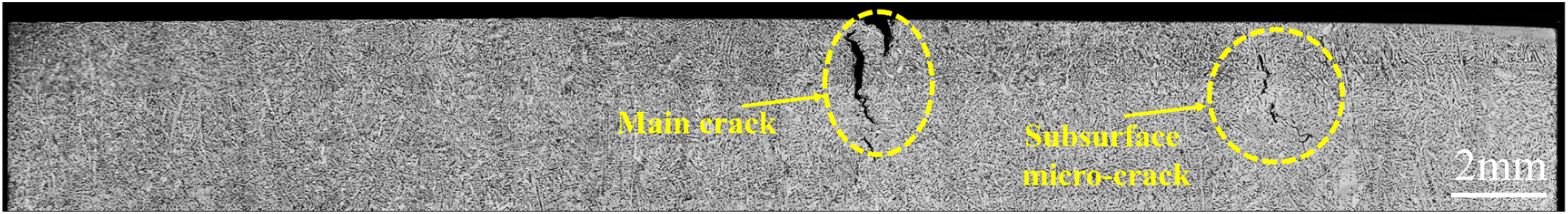
Subsurface cracks at different positions across the width of the strand surface.
Figure 20 illustrates the mechanism of depression formation and its impact on the propagation of the longitudinal surface crack. At time t0, the molten steel solidifies uniformly along the width direction of the meniscus. By time t1, intense cooling or interaction between the slag rim and the initial shell occurs due to local limited infiltration of liquid slag. Consequently, an initial depression forms on the surface of the shell due to volume shrinkage. This initial depression becomes noticeable at the effect of necking by time t2. The formation of the depression slows down heat transfer, making it easier for coarse dendritic structures to form at the bottom of the depression. The enriched solute liquid between these coarse dendrites struggles to solidify and may even promote secondary dendrites to remelt. Under the influence of the negative pressure between dendrites caused by thermal stress, the enriched solute liquid is more likely to form a continuous macro-segregation line, thereby promoting the crack propagation in the depth direction.
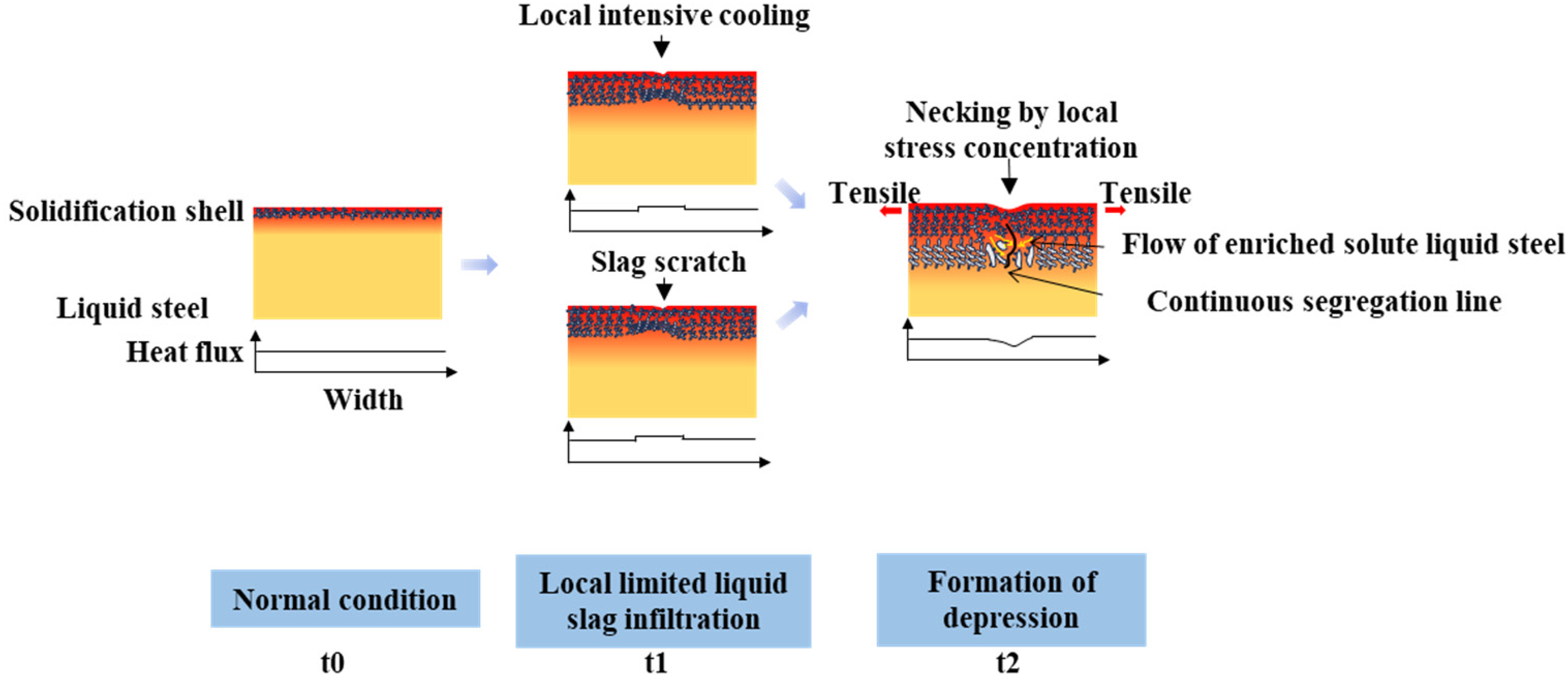
Influence mechanism of longitudinal depression on the crack propagation in the depth direction.
The propagation mechanism for the longitudinal surface crack along the casting direction is depicted in Figure 21. Initially, a surface depression forms on the strand surface due to thermal disturbance, and continued disturbance will lead to the development of continuous longitudinal depression. By time t2, any formed crack easily propagates along the longitudinal depression since the thermal stress concentrates at the depression's bottom. After that, if the mould level fluctuates at time t3, a transverse depression on the shell surface will form under the influence of the slag rim. Consequently, the stress concentration at the transverse depression diminishes, and the original crack stops at this location. However, if the transverse depression cannot alter the preceding thermal disturbance, the initial disturbance continues to develop following the transverse depression. In this scenario, even if the longitudinal crack breaks at the transverse depression, the crack persists in propagating after the transverse depression until the termination of the thermal disturbance. Eventually, the entire crack exhibits a macroscopic morphology parallel to the casting direction. Nevertheless, if the transverse depression alters the primary thermal disturbance, thereby inducing new disturbance at another position adjacent to the transverse depression, it will promote the formation of a new crack and cause the primary crack to shift in the width direction.
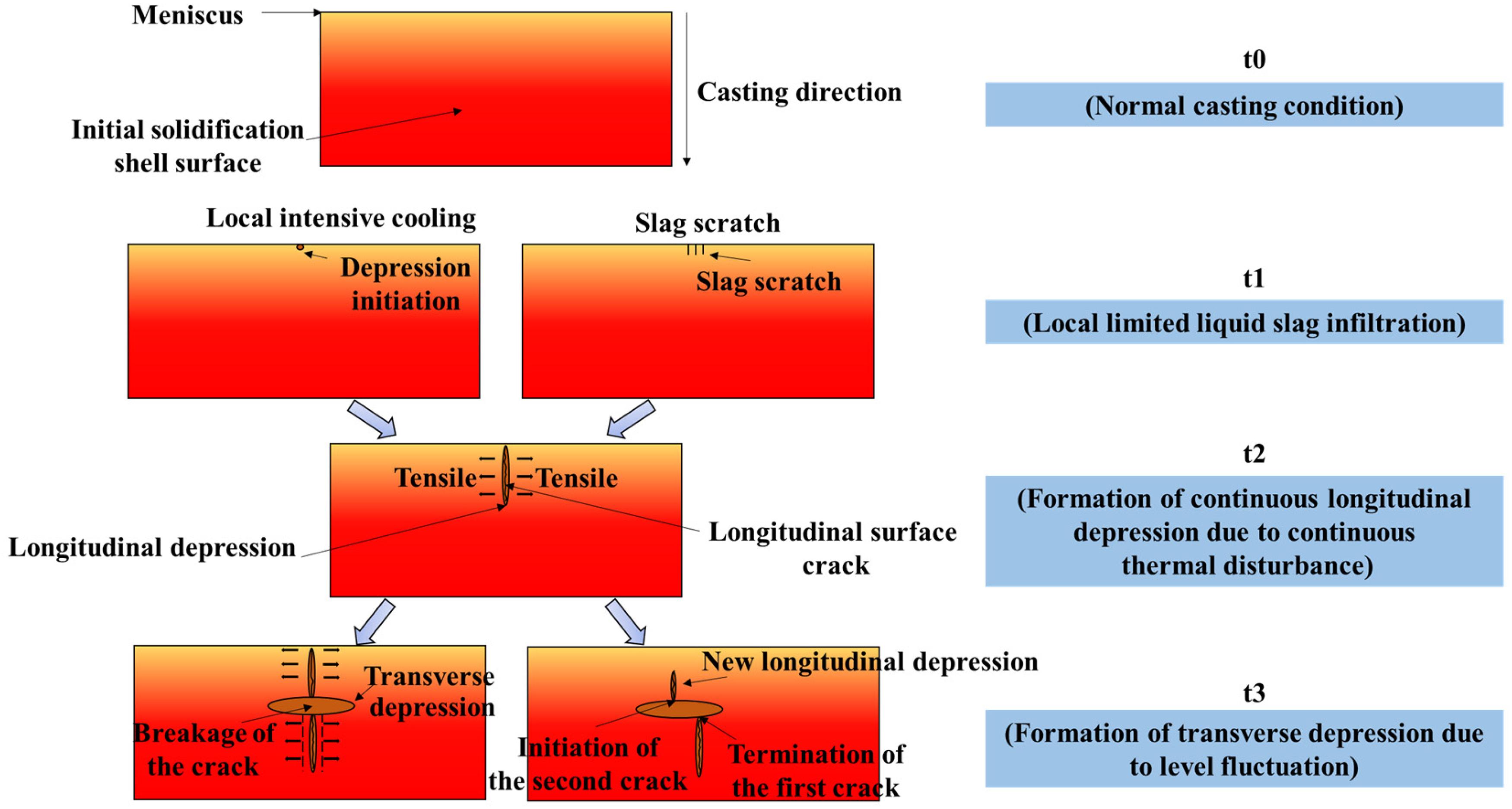
The influence mechanism of depression on crack propagation along the casting direction.
Conclusions
An efficient and accurate method for measuring depression depth across a large area of strand surface was developed using optical auto-focusing. This method effectively detects both longitudinal and transverse depressions, enabling early defect detection and reflecting the irregular solidification characteristics during mould cooling. By comparing the actual measured depression depth, the measurement accuracy of this method can achieve the level of 50 μm. Depression depths were measured for three typical samples with longitudinal surface cracks in hypo-peritectic steel using the developed method. The results showed that longitudinal depression depth increases with depression width and positively correlates with crack width, while transverse depression depth may have the opposite effect. According to the macrostructure characteristics of typical samples, the initiation of surface depression results from the thermal disturbance at the meniscus, decreasing heat transfer of the initial shell and resulting in coarser dendrites in the subsurface area. Furthermore, negative pressure in the inter-dendritic region induced by stress concentration promotes the flow of the solute-rich liquid phase, resulting in a continuous segregation line at the depression bottom. The relationship between crack depth and length of the segregation line satisfies the equation Along the casting direction, continuous local thermal or mechanical disturbances, possibly due to inadequate liquid slag infiltration, result in constant longitudinal depression, facilitating longitudinal crack propagation under the stress concentration. Transverse depression on the strand surface can hinder crack propagation by reducing stress concentration at the depression position. However, new thermal disturbances induced by the transverse depression may change the direction of crack propagation, leading to crack propagation at the new thermal disturbance position. Therefore, minimising longitudinal and transverse depressions are effective strategies for controlling the longitudinal surface crack.
Footnotes
Declaration of conflicting interests
The authors declared no potential conflicts of interest with respect to the research, authorship and/or publication of this article.
Funding
The authors disclosed receipt of the following financial support for the research, authorship and/or publication of this article: This work was supported by the National Natural Science Foundation of China (grant number 52274318).