
Abstract
The briquetting technique holds significant potential to replace traditional iron burden materials due to its lower greenhouse gas emissions. In addition to briquettes’ thermomechanical and metallurgical properties, the blast furnace performance is also considerably affected by the ferrous burden permeability concerning the gas rising through the shaft zone of this reactor. Therefore, this study focused on bed permeability and pressure drop characteristics of iron ore briquettes compared to blast furnaces’ traditional iron ore burdens. Using laboratory experiments and computational fluid dynamics simulations, the research evaluates how different iron burden materials affect gas flow in the blast furnace shaft. The materials tested include sinter, pellets, lump ore, and two types of briquettes (B1 and B2), assessed in both single and mixed beds. The experimental and simulation techniques were in good agreement, and the results indicate that single beds of lump ore, sinter, and briquette B2 exhibit higher permeability, while beds composed exclusively of pellets or B1 briquettes showed lower void fractions, resulting in greater resistance to gas flow and the highest pressure drop. In single beds of B1 briquettes, the pressure drop was approximately 20% higher than that of sinter, while B2 briquettes demonstrated similar permeability and pressure drop to sinter under blast furnace conditions. Mixtures containing pellets also showed increased pressure drops, especially when the pellet mass fraction exceeded 25%, with pressure drops rising by up to 45% compared to sinter beds. Comparisons at varying substitution ratios further indicated that binary beds composed with B1 or B2 performed similarly up to a 50% substitution ratio; however, at a 75% substitution, B2 beds achieved a 10% lower pressure drop than B1 overall, making B2 a potential substitute for sinter to reduce CO2 emissions. These findings underscore the critical role of material geometry and size distribution in optimising blast furnace efficiency.
Introduction
The steel industry is crucial for modern society but faces challenges such as high demand for raw materials, whose quality has been gradually declining, and reliance on carbon-intensive processes. Agglomeration of fines, which are unsuitable for direct use in reduction reactors, is necessary. Sintering and pelletising, the dominant agglomeration methods, require high temperatures (∼1300 °C), leading to substantial CO2 emissions1–4 and harmful byproducts like dioxins and furans.5–10 These environmental concerns highlight the need for alternative, sustainable processes.
Briquetting has emerged as a promising alternative, operating at lower curing temperatures (∼200 °C) and enabling greater incorporation of fine and waste materials.2,4,8,11–14 Briquettes also offer potential process benefits, such as improved efficiency through the use of self-reducing briquettes.15–18 Yu and Shen 19 estimated that loading up to 120 kg of carbon and iron ore composite briquettes per ton of pig iron can reduce the temperature in the thermal reserve zone by approximately 15 K on average. Furthermore, they observed a 1.25% improvement in carbon monoxide utilisation efficiency (from 48.25% to 49.5%) and a productivity boost of 0.12 tons of pig iron/m3/day. Similarly, industrial trials conducted by Bizhanov et al. 15 demonstrated reduced coke consumption, highlighting both environmental and operational advantages.
In countercurrent reactors like blast furnaces, uniform gas flow through the bed is essential for operational stability, increased productivity, and reduced energy consumption, which collectively contribute to lower CO2 emissions. Optimising gas–solid contact relies on particle size distribution and burden stability under reactor conditions.20–24 While higher gas velocities enhance mass and heat transfer and accelerate reduction rates, they can also lead to excessive pressure losses, becoming a limiting factor. Improving bed permeability is a viable solution to mitigate these issues, enabling higher gas velocities without significantly increasing pressure drop.21,25–27
Literature shows that gas velocity profiles in the shaft zone tend to be fairly constant, although this parameter varies widely across studies. For instance, Biswas 27 suggests values ranging from 2 to 20 m/s. A reported26,28 mass flow rate close to 2 kg/m²s in the shaft region, combined with an average blast furnace gas density of 1.38 kg/m3 as reported by Oliveira et al. 29 a resultant velocity of 1.5 m/s was calculated. Simulations by Zhang et al. 25 revealed velocity values between 0.5 and 3.0 m/s, while Li et al. 30 reported a range of 6–10 m/s.
Gas flow in blast furnaces is often modelled using computational fluid dynamics (CFD), coupled with discrete element methods (DEMs) for solid motion.20,24,28,31–34 While these models provide detailed insights into reduction phenomena, they are computationally intensive.24,35 Simplifications like slot and sector models, or even 2D models, reduce costs but may not fully capture the complexity of fluid flow within the furnace.36,37 Porous media models 38 offer an alternative, balancing computational efficiency and realistic permeability evaluations. As highlighted by Li et al., 38 permeability, which directly influences pressure drop in blast furnaces, is essential for low-carbon operations. Notably, the shaft zone alone contributes to 20–30% of the total pressure drop,39,40 underscoring the importance of optimising the permeability in this critical region. Additionally, understanding pressure drop is crucial for designing blowers and pumps and for accurate cost estimation. 41
Several studies have explored the thermomechanical and metallurgical properties of iron ore briquettes,2–4,8,11–14 but the fluid dynamics of briquette-packed beds remain underexplored. Most studies predict pressure drop using the Ergun equation, which assumes spherical particles or approximates non-spherical ones with sphericity. 42 However, this approach is problematic due to the diverse shapes and sizes of materials used in blast furnaces. Guha et al. 43 noted that the Ergun equation is suitable for simple particle beds but requires adjustment for mixed beds with varied material characteristics.
The applicability of Ergun's equation to heterogeneous beds is limited by the diversity in particle shape, size, and surface roughness.43–45 For example, Allen et al. 44 found discrepancies of up to 100% in over-packed beds of non-spherical particles, such as cylinders or cubes. Shitzer and Levy 46 also observed significant underestimation of pressure drop in rock-bed systems with particle sizes ranging from 18 to 45 mm, with errors ranging from 1.5 to 5 times lower than experimental measurements. Koekemoer and Luckos 45 tested three different materials – coal, char and ash – showing significant variations in sphericity, which further complicates the application of the original Ergun equation. The original coefficients (150 and 1.75) for predicting pressure drop were found to be inadequate. By adjusting the coefficients, new values were derived for each material: coal (77.4 and 2.8), char (160.4 and 2.8), and ash (229.7 and 2.3). These modified coefficients resulted in a better alignment with experimental data, reducing the average error from 29% to 9%.
Although sphericity was introduced as a factor in the original Ergun equation to account for deviations from spherical shapes, its accurate determination remains a challenge, particularly for irregular particles. Moreover, surface roughness further complicates pressure drop predictions. Increased roughness enhances porosity by hindering particle packing and creating additional gas flow pathways. However, it also amplifies particle-gas friction, raising pressure drop.47,48 These factors are not fully addressed by the original Ergun equation, necessitating model adaptations for industrial applications.
Such deviations highlight the challenges in applying classical correlations to heterogeneous particle systems and the importance of understanding the fluid dynamics of briquette-packed beds. These complexities require alternative approaches or the calibration of existing models to accurately predict pressure drops in industrial scenarios, where particle heterogeneity and irregularity are the norm. Therefore, this study aimed to evaluate the influence of iron ore briquettes on the permeability of granular beds through experimental and numerical simulations, comparing their performance with traditional ferrous burden used in blast furnaces. The study contributes to operational improvements and environmental benefits by exploring alternative raw materials and reducing the environmental impact of the ironmaking process.
Materials and methods
Raw materials
In this study, five different ferrous burden materials were evaluated (Figure 1): lump ore (L), pellets (P), sinter (S), and two types of briquettes (B1 and B2), which differ in both dimensions and geometry. Table 1 provides the key characteristics and physical properties of these raw materials. As can be observed in this Figure 1, Briquette B1 is characterised by a flat and regular geometry, while Briquette B2 exhibits an ellipsoid shape.
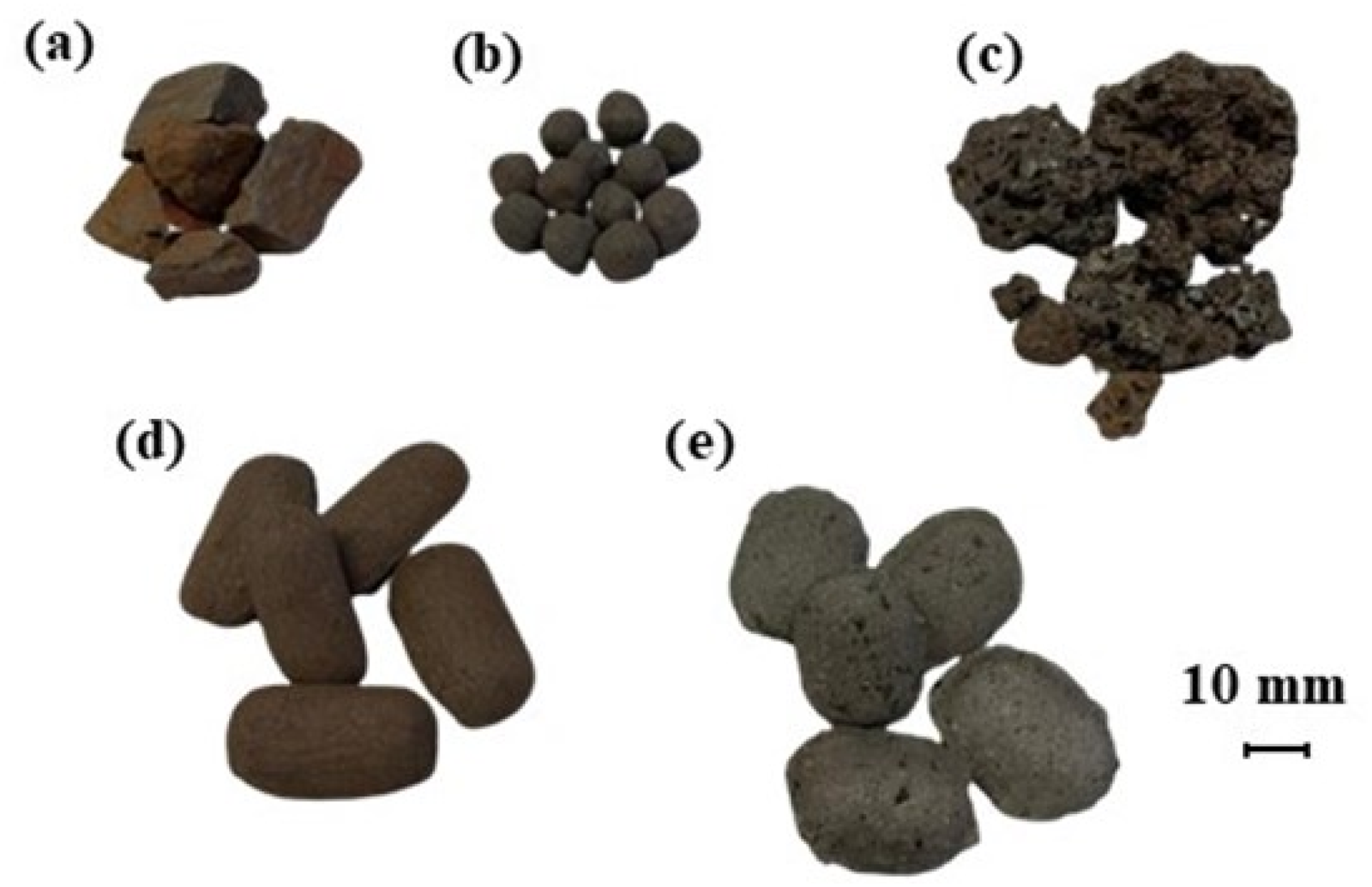
Raw materials evaluated in this study: (a) lump ore, (b) pellet, (c) sinter, (d) briquette B1, and (e) briquette B2.
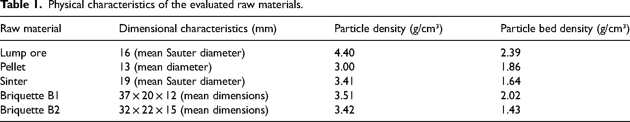
Physical characteristics of the evaluated raw materials.
The briquettes used in this work were cured at relatively low temperatures (∼200 °C) and were sourced from two different suppliers. Details regarding the binder composition, physical, chemical and metallurgical properties of the briquettes, while important in a broader context, fall outside the intended scope of this research, which investigated how the geometric characteristics of the briquettes influence bed permeability, providing insights into the effects of their shape and dimensions under experimental conditions.
In addition to the primary dimensions shown in Table 1, the particle size distribution of lump ore and sinter is presented in Figure 2. Sinter has a broader particle size range compared to the other materials, with a significant fraction of particles between 20 and 38 mm, while lump ore is predominantly between 12 and 20 mm. Both pellets and briquettes exhibit a uniform size distribution, which is typical of their respective production processes.
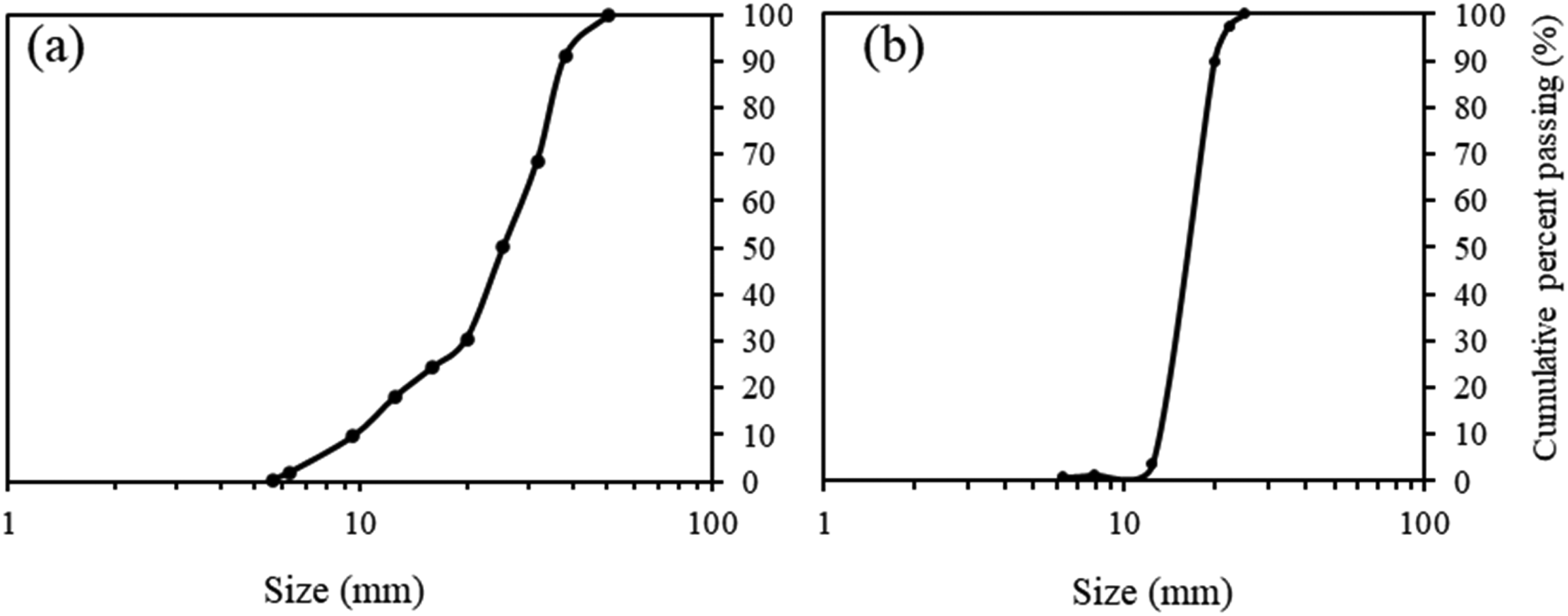
Particle size distribution of (a) sinter and (b) lump ore.
Experimental – permeability tests
Permeability tests were conducted using a physical model consisting of a laboratory-scale permeameter (Figure 3). The apparatus includes a hollow cylindrical tube (150 mm in height and 123 mm in diameter) with a great fitted at the bottom. This tube is connected to a wind box, featuring one outlet for a flow meter and another for a manometer, enabling measurement of the differential pressure between the top (atmospheric pressure) and the base (pressure in the wind box) of the particle bed. The setup also includes a manual needle valve for flow control and a fan at the end of the tubing, capable of generating suction.
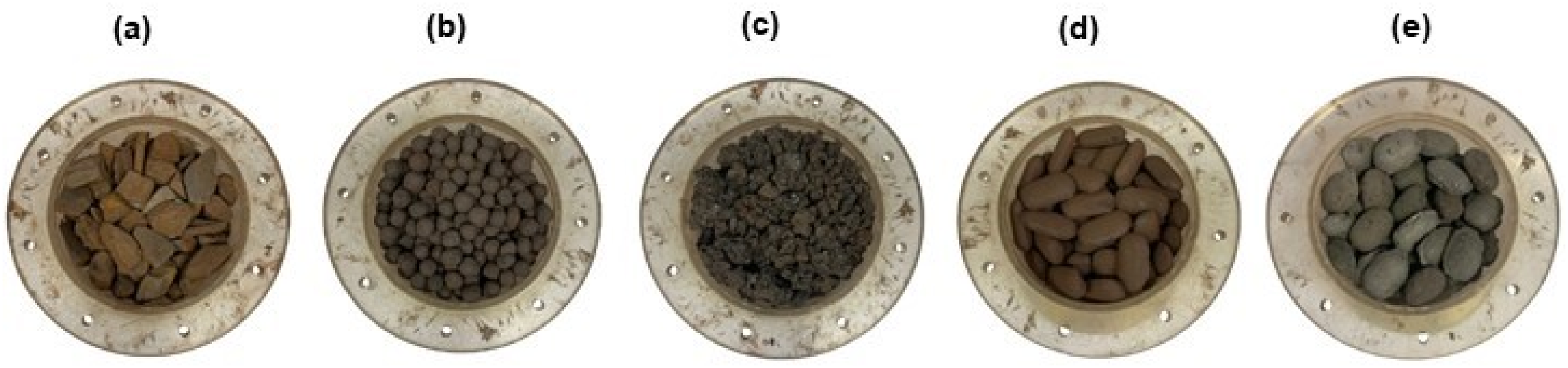
Images of single particle beds for each material: (a) lump ore, (b) pellet, (c) sinter, (d) briquette B1, and (e) briquette B2.
In this study, the ratio between the chamber diameter and the average particle size ranged from 5.4 to 9.5. Based on the findings of Guo et al., 49 this range is within the threshold where boundary effects are not significant. Moreover, this setup allowed for a higher number of tests, enabling a broader set of combinations between different iron burden materials.
For the tests, each raw material was homogenised and randomly loaded into the permeameter tube using a chute. The pressure difference was measured at various gas flow rates, and based on these values, the permeability of the different beds was calculated in JPU (Japanese Permeability Unit, commonly used for evaluating iron ore sinter beds) according to Equation (1). In this equation, F represents the air flow rate (m³/min), A is the cross-sectional area of the bed (m²), L is the bed height (mm), and ΔP is the pressure drop across the bed (mmH₂O).50,51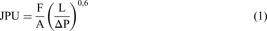
The ferrous burdens were evaluated in various bed combinations, as shown in Table 2, while maintaining a constant bed volume. Initially, each raw material was tested individually in the permeameter. Subsequently, binary beds were tested, consisting of mixtures of briquettes (B1 or B2) with other raw materials at 25%, 50%, and 75% by mass. These mixtures aimed to assess the behaviour of briquettes concerning the permeability. Finally, beds composed of 70% sinter, 20% pellets, and either lump ore or briquettes (at 5% and 10%) were evaluated to approximate the typical composition of charge materials used in domestic blast furnaces, with partial or full replacement of lump ore.
Composition of raw material beds for permeability tests.
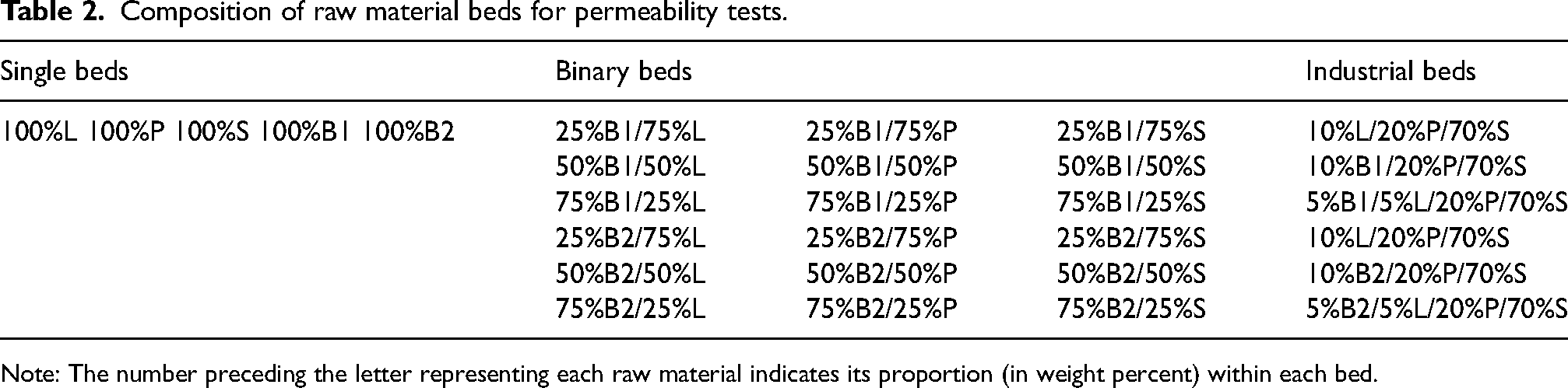
Note: The number preceding the letter representing each raw material indicates its proportion (in weight percent) within each bed.
Figure 3 shows the cylindrical tube of the permeameter filled with individual beds of each raw material evaluated in this study.
Void fraction is a key parameter influencing bed permeability, as these voids create pathways for gas flow. Equation (2) was used to calculate the void fraction (
where ρB stands for the particle bed density of each ferrous burden, determined by the mass inside the permeameter and its volume (interparticle void volume + particle volume), and ρa is the particle density.
Mathematical modelling – numerical simulation
The numerical simulations were carried out using CFD software, Ansys®-Fluent, version 2021 R1. Initially, the conditions tested in the physical model were simulated for validation purposes. One-quarter of the blast furnace shaft with typical dimensions was used for industrial conditions simulations as the calculation domain (Figure 4). Gas transport properties, such as viscosity and density, were assumed constant at specified values. The model selection, descriptions, simplifications, and boundary conditions were based on the Ansys®-Fluent Solver Theory Guide 52 and relevant literature.20,21,25,35,53–56
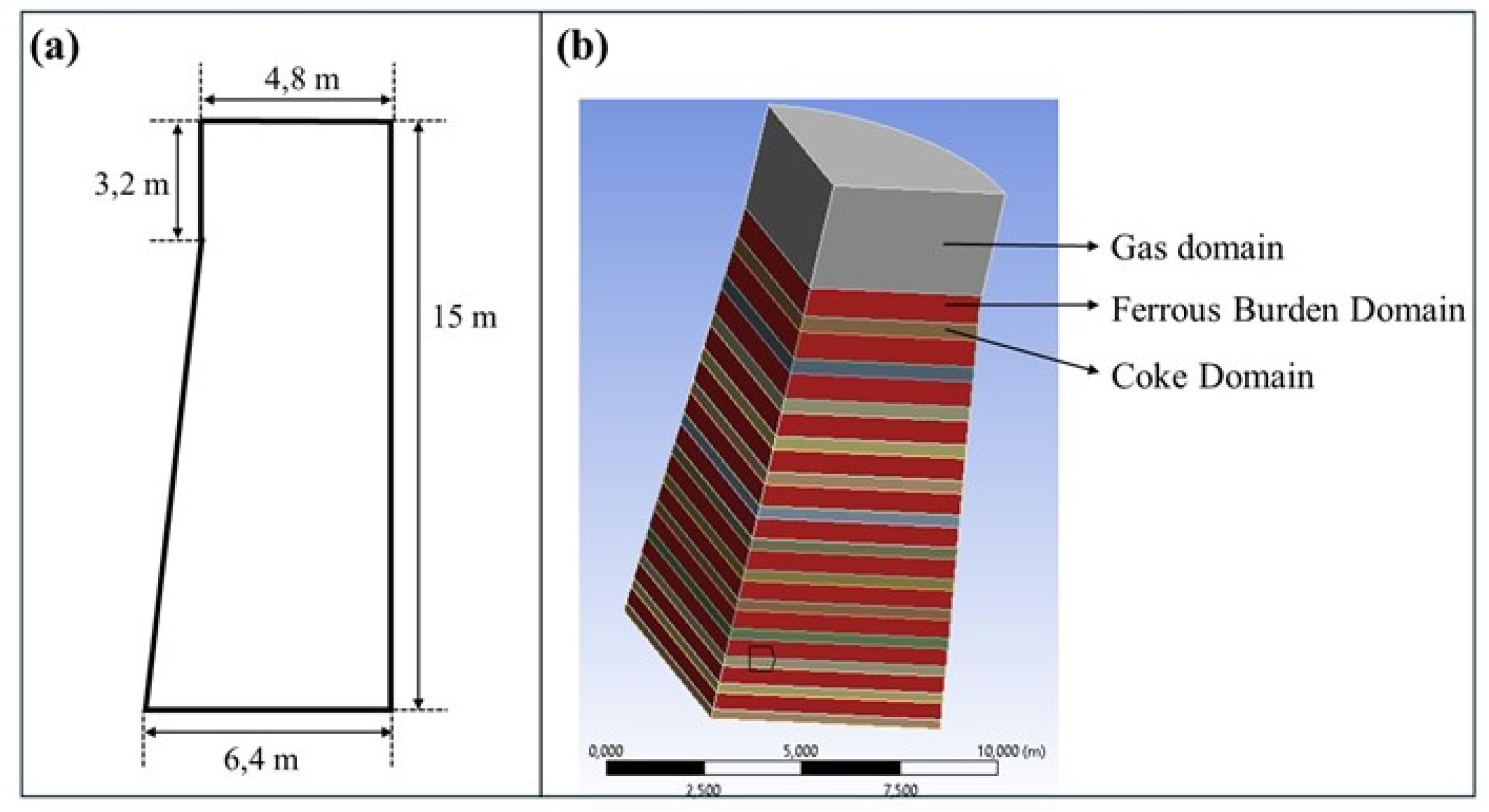
Schematisation of the reactor geometry with (a) dimensions and (b) domains.
The porous media model was employed in this study. This approach considers a bed of solid particles with uniformly distributed voids. This model is particularly advantageous for simulating the blast furnace, where the network of porous beds is highly complex and extensive, making direct discretization computationally prohibitive. 52 Although this assumption may seem inadequate for blast furnace applications, the pressure drop coefficients utilised in the simulation were derived from non-uniform beds with actual materials. As a result, the irregularities in the pore network are embedded in the coefficients. This emphasises the importance of this study in providing pressure drop coefficients that accurately reflect the characteristics of beds containing iron ore briquettes and traditional iron burden materials.
Governing equations
The software code utilises a finite volume method to solve the differential equations governing fluid flow, including the following:
Mass conservation equation for the gas phase:
Conservation equation for momentum, turbulent form of the Navier–Stokes equations: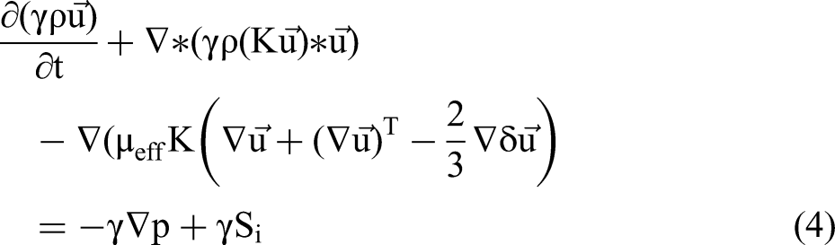
Effective viscosity:
Turbulence kinetic energy: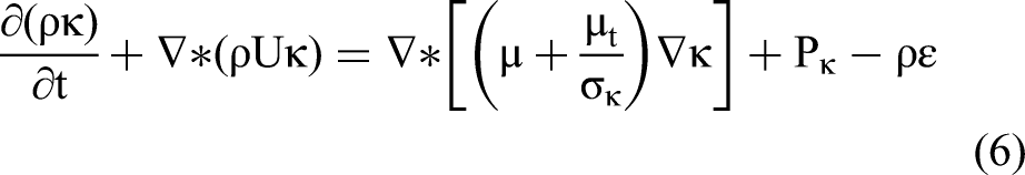
Turbulent kinetic energy dissipation: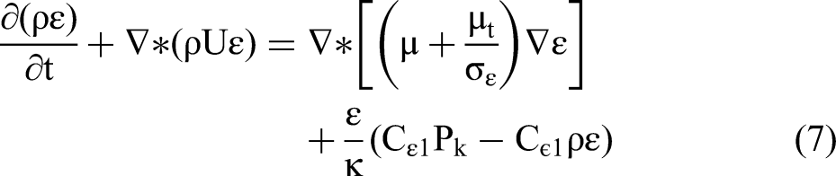
Turbulent viscosity:
where γ is the void fraction of the particle bed; ρ is the gas density (kg/m³); t is time (s); ∇ is the gradient operator; U is the mean velocity component (m/s); µeff is the effective viscosity (Pa.s); 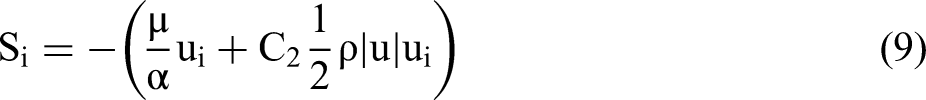
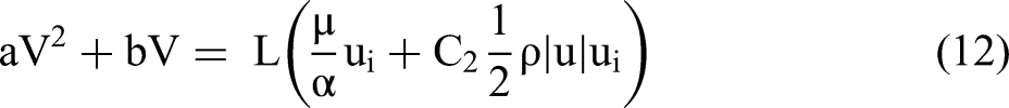
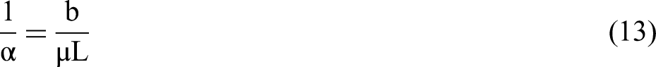
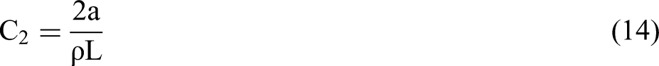
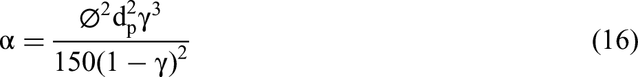
The source term has units of force per volume, which is equivalent to the pressure drop (ΔP/L). The α and C2 coefficients for the ferrous burden were derived from the experimental results obtained through physical modelling. In this case, a curve of ΔP versus gas velocity was plotted, as shown in Figure 5.
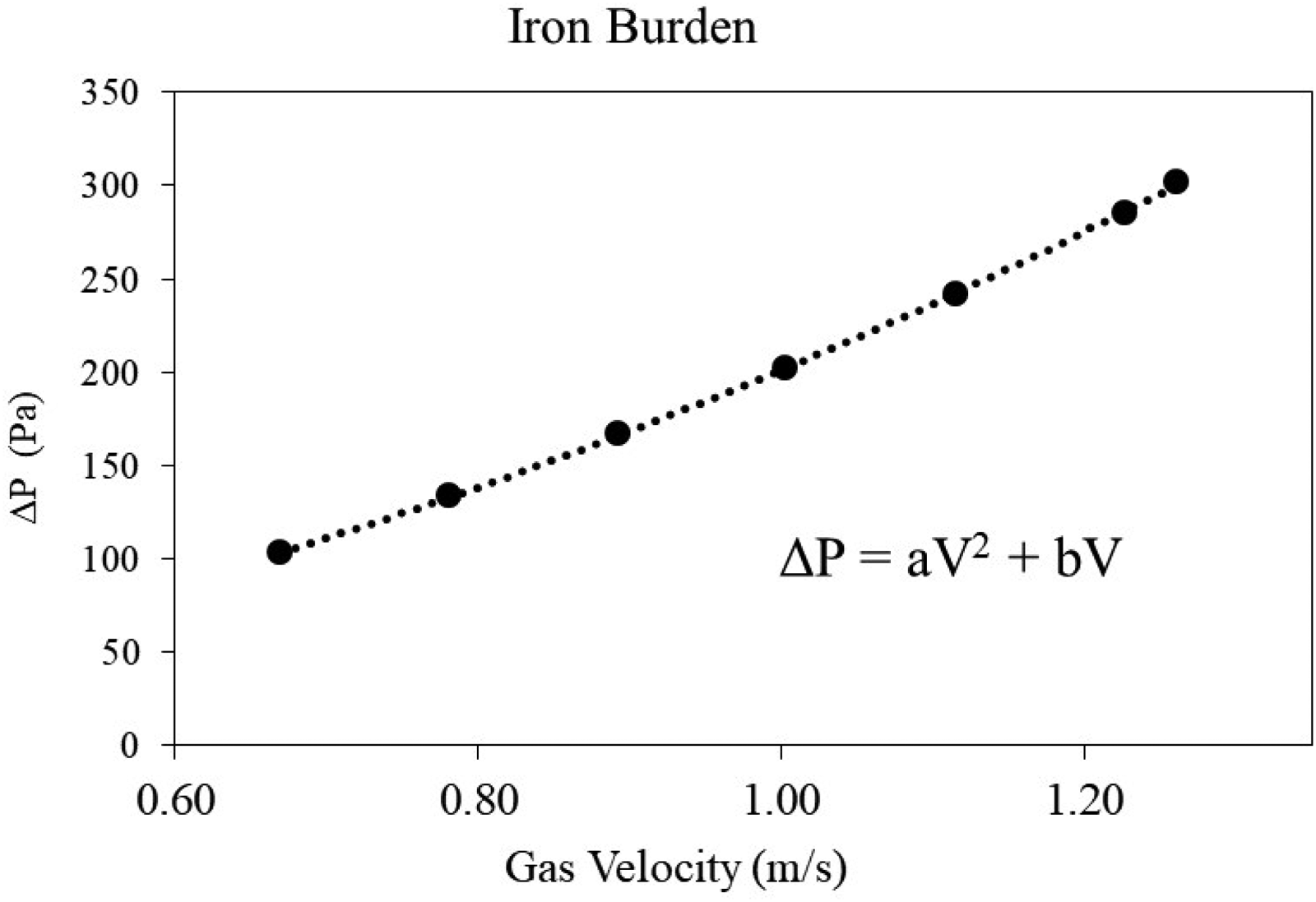
Schematic representation of the relationship between pressure drop and gas velocity.
By comparing the relationship shown in Figure 5 with the source term equation, and considering the source term defined by the pressure drop, the α and C2 coefficients were derived as follows:

For the coke layers, since this study focuses on the ferrous burden, the coefficients α and C2 were derived from the Ergun equation as follows: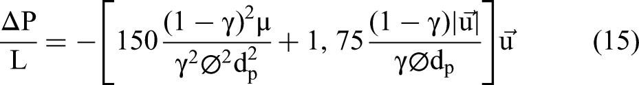
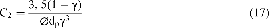
where ø is the sphericity of the particle, defined as the ratio of a particle's surface area to the surface area of a sphere with the same volume. The bed and particle parameters required to calculate α and C2 for the coke layers were obtained from the literature and maintained constant for all simulations.
Boundary conditions and simplifications
This modelling considers only the lump zone of the blast furnace, as this region has the most significant impact on gas flow resulting from the ferrous burden. Below this zone, the ferrous raw materials begin to soften and melt, making the void fraction of the coke structure a key factor in controlling gas flow.
The gas velocity was specified at the base of the shaft as a boundary condition, with the velocity magnitude falling within the range reported in the literature. The blast furnace shaft was divided into alternating layers, each containing a constant amount of coke and ferrous burden. As the reactor's diameter increases from top to bottom, the layer thickness decreases, varying within the range of 0.25 to 0.8 m, as reported in the literature. The thickness of each layer was determined using material consumption rates and particle bed density of 1640 kg/m³ for the ferrous burden and 780 kg/m³ for coke. A coke rate of 350 kg per ton of hot metal was considered, while the ferrous burden consumption was set at 1500 kg per ton. Although the specific consumption of coke and ferrous burden, as well as the bulk density of the ferrous burden, can vary with different types of ferrous burden, this variation was neglected for the purposes of this study, which aims to evaluate the pressure drop caused by the geometry of the iron ore material and the characteristics of the bed. A gas phase domain was considered above the last solid layer at the top of the furnace.
Similar to the study by Zhang et al., 25 this work considers the interface between the ferrous burden layer and the coke layer to be thin enough that the mixed layer can be disregarded.
Results and discussion
Void fraction – single and binary beds
Figures 6 and 7 present the void fraction data obtained from the experimental tests. Briquette B2 formed a bed with the highest void fraction (0.58), whereas Briquette B1 exhibited a lower void fraction (0.42). Among the traditional raw materials, the sinter bed has the highest void fraction (0.52), while the pellet bed exhibits the lowest (0.38). The lump ore bed has a void fraction that falls between those of the pellet and the sinter beds.
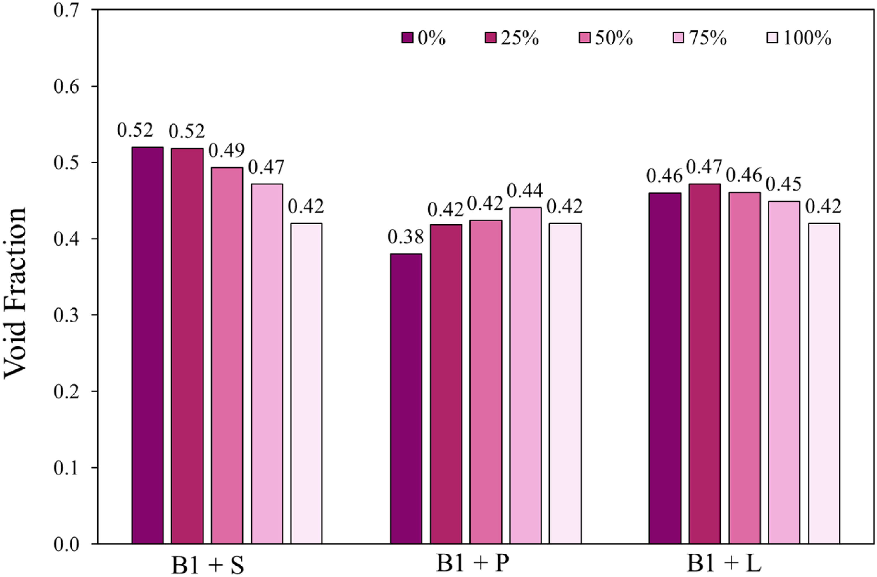
Void fraction of binary ferrous burden beds with the addition of B1.
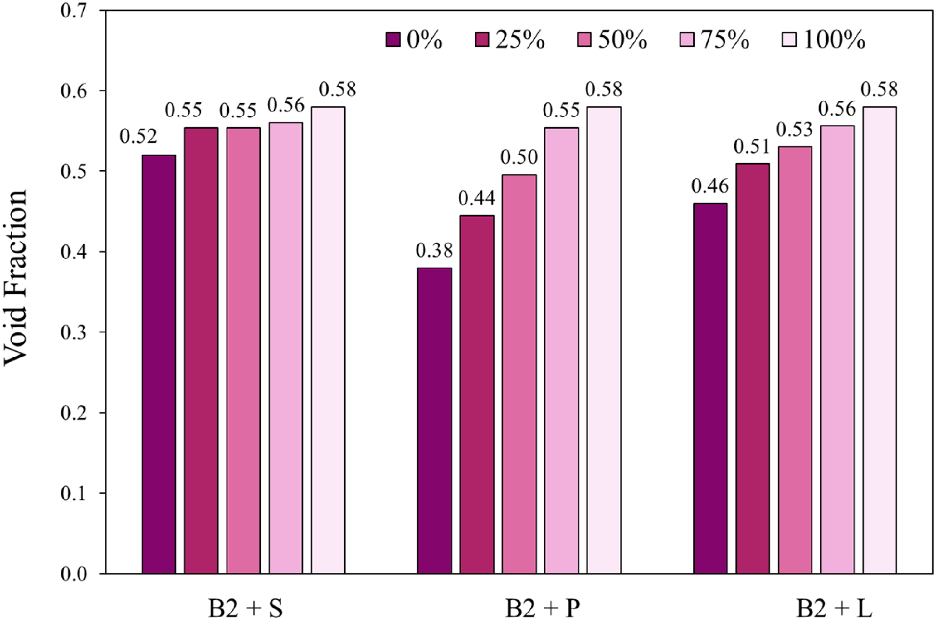
Void fraction of binary ferrous burden beds with the addition of B2.
Iron ore pellets, due to their spherical shape, tend to form a compact bed, which minimises void spaces and results in efficient packing. In contrast, the irregular geometry of sinter and lump ore decreases particle packing, which is beneficial for the formation and interconnection of voids within the bed. Briquette B1, with its flat and regular geometry, promotes the formation of a compact bed, with particles well-arranged in overlapping multilayers. On the other hand, although Briquette B2 has regular shape, it is neither flat nor spherical, preventing excessive particle compaction and resulting in a higher void fraction. It is important to note that these observations regarding the influence of particle shape on void fraction were only possible because the beds lacked a significant fines fraction. Therefore, the particle size distribution on the beds tested allowed the effects of particle geometry differences to be more clearly distinguished and quantified.
For mixture beds composed of Briquette B1 and common iron burden materials, a more pronounced impact was observed when combining B1 with sinter (B1 + S). As the mass fraction of B1 exceeds 25%, the void fraction decreases significantly. In contrast, in the case of the pellet bed (B1 + P), the void fraction increases as the B1 mass fraction rises. However, for the lump ore bed (B1 + L), the addition of B1 has little to no effect on the void fraction.
Regarding the B2 mixture with sinter (B2 + S), no significant difference in void fraction was observed. For the B2 + P mixture, as the briquette mass fraction increased, a pronounced rise in void fraction was observed. The mixture B2 + L showed a greater impact on bed permeability compared to B2 + S but was less pronounced than the effect observed with B2 + P.
Permeability – single and binary beds
Figure 8 illustrates the influence of void fraction on permeability index measured experimentally for single beds. As observed, there is a tendency to increase permeability with void fraction, which is expected as there is more space available for gas flow.
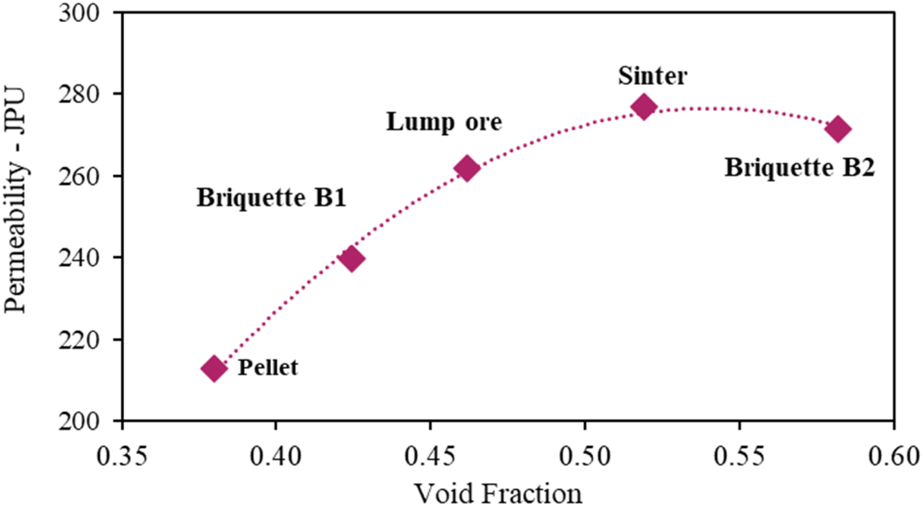
Permeability of individual beds of the different ferrous burdens.
Briquette B2 exhibited only a slightly higher void fraction than sinter, with permeability tests showing no significant difference between these two agglomerates under the physical modelling conditions. This suggests that the disparity in permeability may be related to the connectivity of voids within the bed. In the briquette bed, the more regular shape of the particles likely leads to less efficient void connectivity. Although Briquette B2 has a slightly higher void fraction, the network of channels between voids is less developed compared to the sinter bed. In contrast, despite sinter having fewer voids, it forms a more effective network of interconnected void spaces due to its irregular geometry, allowing for better gas flow through the bed in the experimental conditions.
This highlights the importance of pore connectivity over void fraction alone in determining permeability. Given that the objective of this study is to develop correlations between the particle geometry and macroscopic observations, such as permeability and pressure drop, no additional evidence at the microscopic level is required to support the hypothesis of pore connectivity.
Briquette B1 and pellets, in addition to their lower void fraction, have poorer connectivity between voids, which further limits their overall permeability. Moreover, in the case of the pellet bed, the friction area of this material plays a significant role. Since pellets have a smaller mean size, they possess a higher specific contact area, which contributes to increased energy loss during gas flow.
The permeability for binary beds, which are composed of two raw materials, is presented in Figures 9 and 10 and corresponds to the variation of mass fraction of briquettes B1 and B2, respectively. These results are correlated with the data presented in Figures 7 and 8, which show the void fraction calculated for each mixture bed.
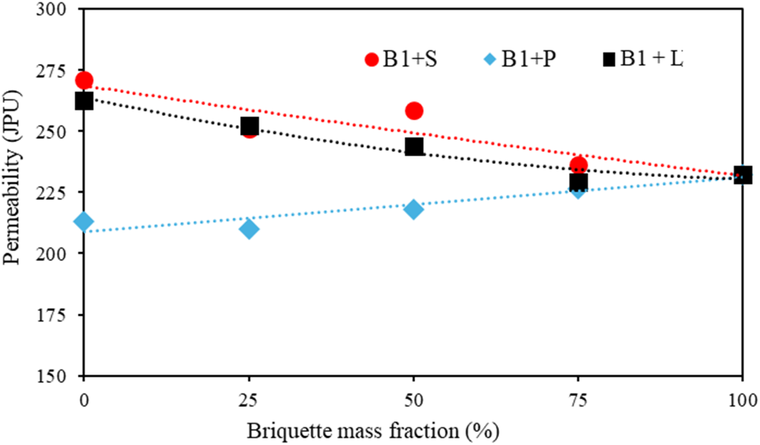
Permeability of beds in binary combinations with B1.
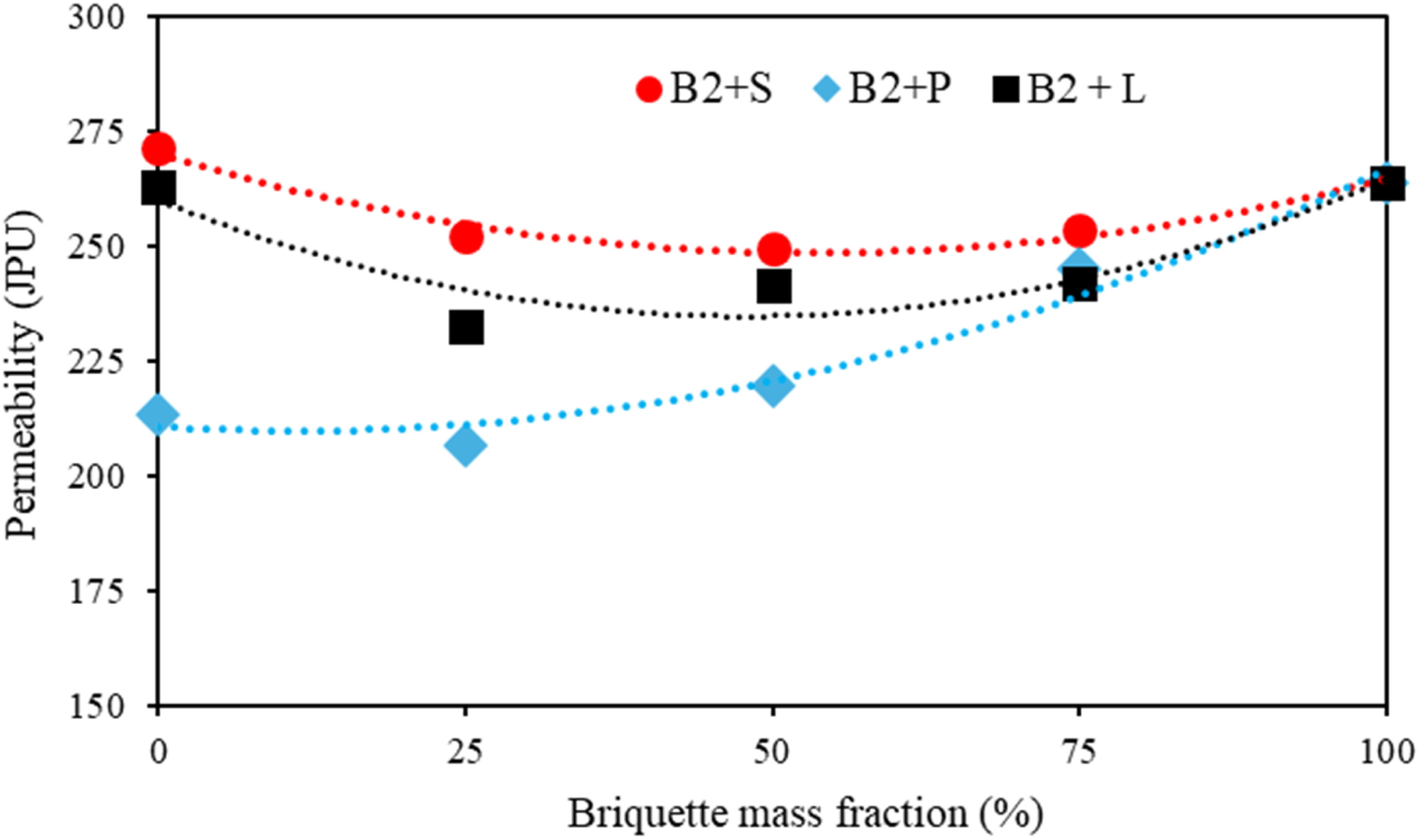
Permeability of beds in binary combinations with B2.
For mixture beds composed of Briquette B1 and common iron burden materials, distinct behaviours were observed depending on the counterpart material. In B1 + S beds, the void fraction decreases significantly beyond 25% B1, likely due to the compact nature of B1 within the sinter matrix. Conversely, in B1 + P beds, the void fraction increases as B1 disrupts the highly compact pellet structure. In B1 + L beds, the angular geometry of the lump ore appears to counteract significant changes in void fraction, tending to maintain the bed's original structure.
The B2 addition forms a bed with permeability similar to that of lump ore and sinter beds, but B2 does not continuously decrease bed permeability as B1. Initially, permeability decreases with B2 addition (up to 25% when combined with lump ore and up to 50% with sinter), and with greater proportions it increases again. The pellet bed, in contrast, shows a continuous increase in permeability with B2 addition, exceeding the increase observed with B1.
These results are aligned with the data found for individual beds, where B2, sinter and lump ore exhibit higher permeability values compared to B1, while pellets, in contrast, have a less permeable bed.
In general, mixtures containing sinter and both types of briquettes exhibit better permeability compared to mixtures with pellets or with lump ore. Additionally, both briquettes improve the permeability of the pellet bed.
Industrial beds permeability
The permeability of industrial beds, formed by mixtures of more than two raw materials, is shown in Figure 11. As can be observed, small briquettes added to industrial beds do not significantly impact permeability. The void fraction does not show large changes either. The same magnitude order of the particle size of briquettes and lump ore, and the restricted participation of them in the burden mixture can explain this similar performance. Then, these results suggest that briquettes do not affect the permeability performance of industrial charges when added in small amounts, aiming, for example, to replace lump ore, whose availability is decreasing due to declining quality. Therefore, in terms of permeability, briquettes have the potential to be used as partial charges in blast furnaces. Additionally, there are environmental benefits from using an agglomerate with lower energy consumption and CO2 emissions, promoting iron production with a smaller carbon footprint.
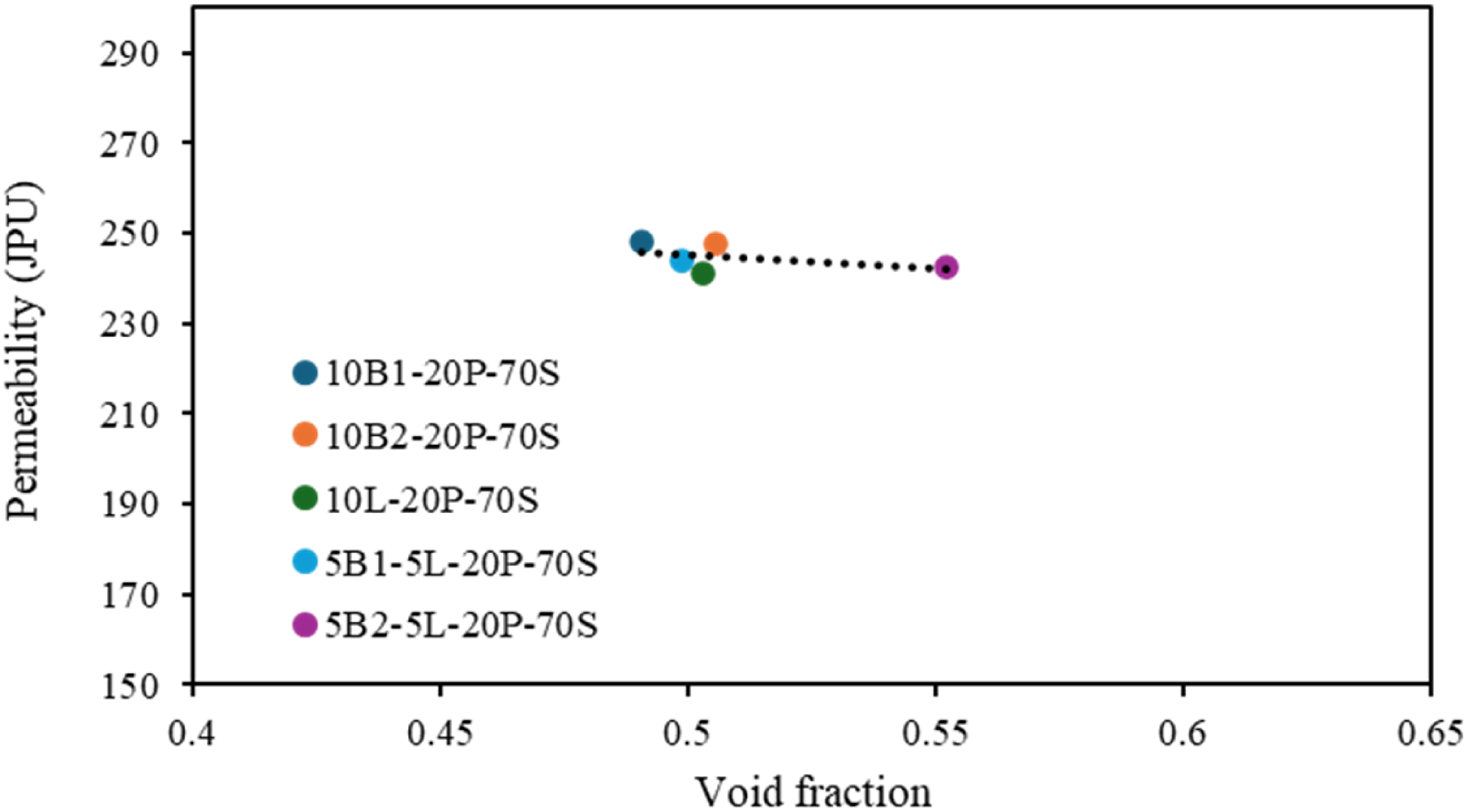
Permeability of industrial beds with the addition of B1 and B2.
Numerical simulations – permeameter set up
Figure 12 presents data from a series of simulations using the physical model conditions for single raw material beds as well as for some mixture beds. This step is important for validating the CFD model. As observed in Figure 12(a), the single beds of lump, sinter, and B2 exhibited the lowest pressure drop, which aligns with the previously presented permeability data. This is associated with both geometry and particle size distribution. In the case of pellets and B1, the pressure drop is higher due to the lower void fraction of the bed, as well as poor void connectivity.
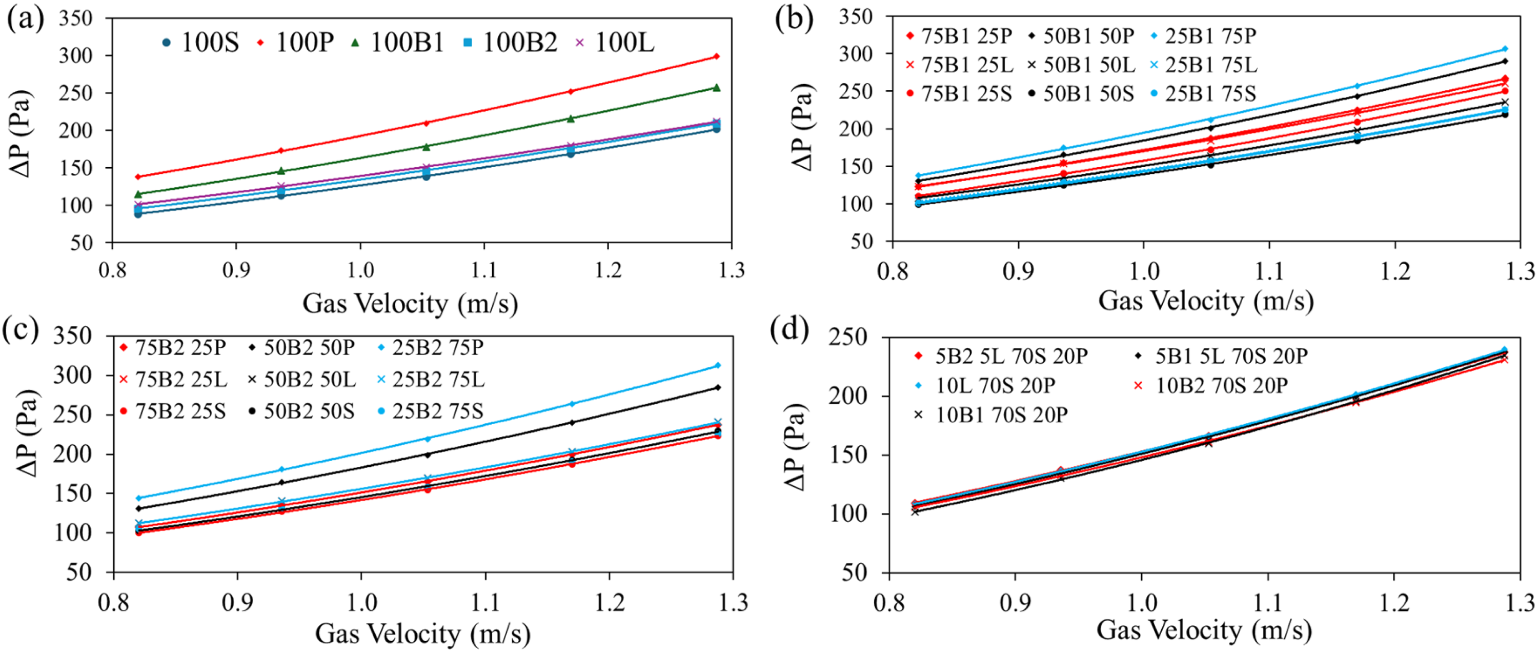
Influence of gas velocity on pressure drop in the permeameter: (a) single beds; (b) binary beds with B2; (c) binary beds with B1; (d) industrial beds.
In Figure 12(b) and (c), simulations involving the addition of briquettes (B1 and B2) to the traditional blast furnace raw materials are presented. In general, at up to 50% substitution, there is little difference between binary beds of B1 and B2. However, with a higher substitution ratio of 75%, the pressure drop is approximately 10% lower for the bed composed of briquette B2, regardless of gas velocity.
The bed performance, when composed of briquettes (B1 and B2) and pellets, was lower, as the spherical pellets tend to occupy the interstices between briquettes. For cases where three or more raw materials were used in proportions that represent the industry, Figure 12(d), no significant difference in pressure drop was observed among the beds.
A strong correlation was observed between the numerical simulation results and the physical model, with a maximum deviation of only 2.3%.
Numerical simulations – blast furnace set up
After validating the CFD code with physical experiments, simulations under industrial conditions were performed and are presented in Figure 13. As expected, the pressure drop (ΔP) varies quadratically with gas velocity. Moreover, the pressure drop becomes excessive at gas velocities above 6 m/s. In the blast furnace, pellets and B1 exhibit the highest pressure drops, both as individual raw materials and as components of the bed.
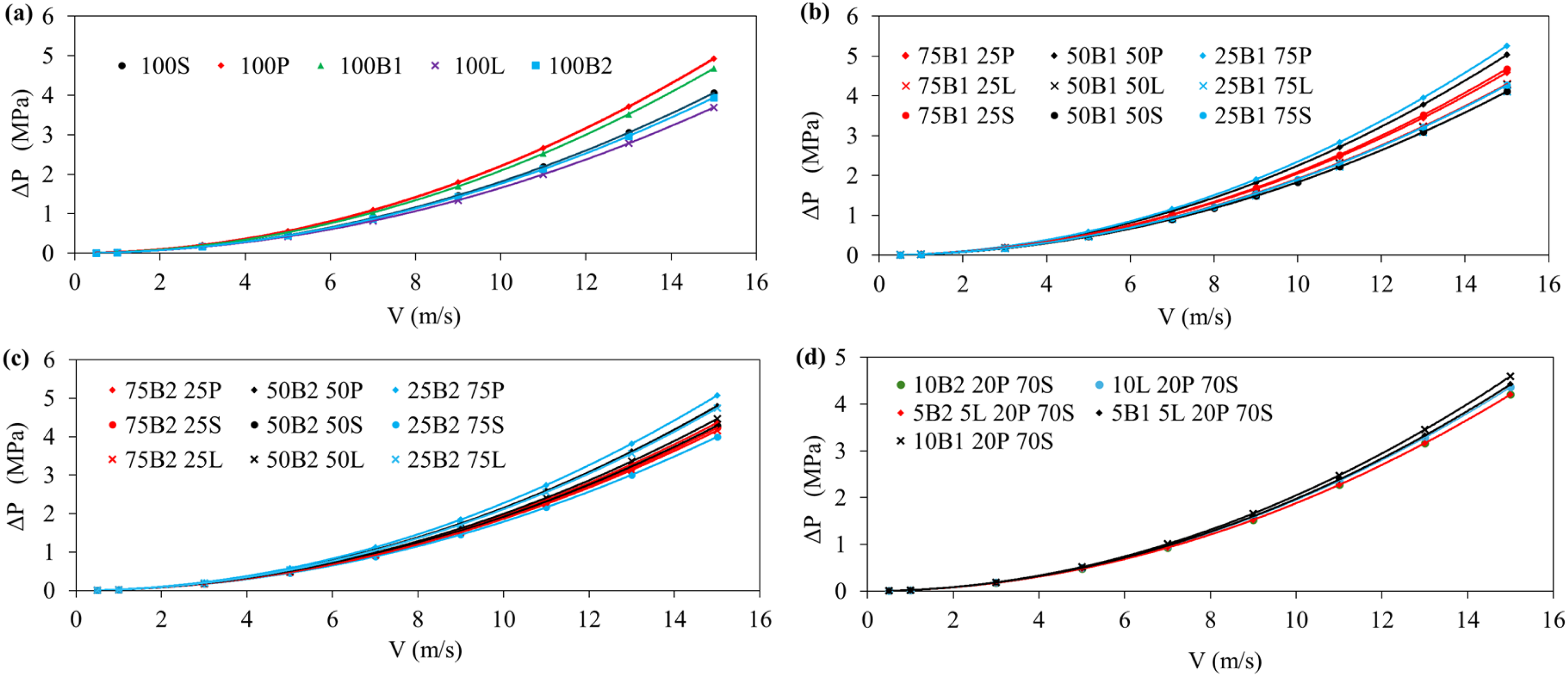
Influence of gas velocity on pressure drop in the lump zone of the blast furnace: (a) single beds; (b) binary beds with B1; (c) binary beds with B2; (d) industrial beds.
As shown in Figure 13, at high gas velocities, the results for the three best bed charges slightly diverge from the predictions made in permeameter simulations. The bed composed of lump ore shows the lowest pressure drop, followed by the B2 briquette bed and, finally, the sinter bed. In general, binary beds show a tendency for better performance with B2 briquettes, especially at high gas velocities and high substitution rates. In the case of industrial beds, less significant differences are observed, as shown by the previous results from physical modelling.
For easier pressure drop comparison, a normalised pressure drop has been adopted. In this case, the pressure drop of each bed (ΔPi) is divided by the pressure drop of the most common blast furnace ferrous bed, which is composed of sinter (ΔPSinter).
Figure 14 presents the normalised pressure drop for the beds under study and under blast furnace conditions. Among the single beds, the lowest performance was observed for the pellet bed followed closely by the briquette B1 bed, which demonstrated the highest pressure drop. In contrast, briquette B2 and lump ore beds showed better performance.

Normalised pressure drop in the lump zone of the blast furnace: (a) single beds; (b) binary beds with B1; (c) binary beds with B2; (d) industrial beds.
In addition to its low performance as a single bed, the pellet also exhibited the highest pressure drop when used as a component in a mixture. For binary beds with pellet mass fractions exceeding 25%, the highest pressure drop was observed. For these beds, the normalised pressure drop (the ratio ΔPPellet/ΔPSinter) ranged from 1.25 to 1.45, indicating an increasing of 25% to 45% in pressure drop compared to the single sinter bed. The use of briquette B1, in most cases, whether alone or in combination with sinter or lump ore, resulted in a pressure drop increase that was lower than that caused by pellet addition, with a maximum increase of approximately 20% (ΔPi/ΔPSinter = 1.2).
As shown in Figure 14, at low gas velocities (V < 2.0 m/s) all the beds exhibited an increase in pressure drop, with normalised pressure drop values exceeding 1.0, which are consistent with the experimental conditions. At higher gas velocities, the normalised pressure for the lump ore bed is approximately 0.91, indicating a pressure drop about 9% lower than that of the sinter bed. Additionally, at high gas velocities, two binary beds (50B1 + 50S and 25B1 + 75L) exhibited nearly the same pressure drop as the sinter bed (ΔPi/ΔPSinter ∼ 1.0). As previously mentioned, the addition of 50% B1 to the sinter bed reduces the void fraction; however, this effect is likely suppressed by the enhancement of void connectivity. In the case of 25% B1 added to the lump ore bed, the void fraction remains nearly unchanged. At high gas velocities, the single B2 briquette and 25B2 + 75S beds exhibited a slight reduction in pressure drop compared to the sinter bed (ΔPi/ΔPSinter < 1.0). In both cases, the void fraction and permeability increased, justifying the improved performance.
These observations regarding the performance of lump ore and B2 compared to the sinter bed under blast furnace conditions are noteworthy, particularly given the differing results obtained from laboratory simulations versus industrial conditions. These findings also highlight the importance of simulating the aerodynamics of the blast furnace under industrial conditions, since they help to determine the optimal geometry of the briquette to maximise bed permeability within the process, thereby enhancing productivity, gas utilisation efficiency and the consequent reducing CO2 emissions.
Even though the lump ore bed presents a lower pressure drop compared to the sinter bed, it is worth emphasising that this type of material varies widely in geometry and size, depending on its source, processing, and handling. Furthermore, this material has become increasingly scarce, which further limits its availability for use.
The beds composed of three or more types of raw materials (Figure 14(d)) showed a pressure drop increase compared to the sinter bed, ranging from approximately 5% to 20%. The highest pressure drop was observed in the bed composed of 10% B1, 20% pellets, and 70% sinter, while the lowest pressure drop occurred in the beds with the addition of briquette B2.
As can be seen in the graphs displayed in Figure 14, the relationship ΔPi/ΔPSinter remains nearly constant as the velocity increases beyond a certain value, ranging from 1 to 3 m/s, depending on the type of raw material. When the gas velocity drops below this value, ΔPi/ΔPSinter continuously increases.
The explanation for this behaviour can be summarised by equations (18)-(21), discussed following.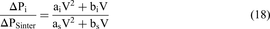
This can be simplified to:
As the gas velocity increases, the term aV tends to dominate over the coefficient b, allowing equation (19) to be simplified further as follows:
For low gas velocities, where b>>aV, Equation 19 can be simplified to:
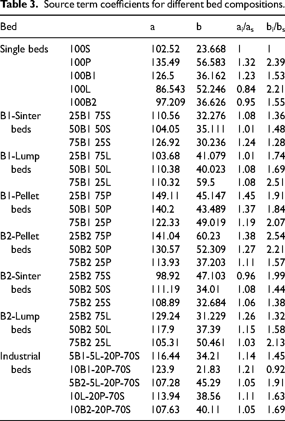
As a simplification, and for comparison purposes, it can be stated that at high gas velocities, the pressure relationship is majority defined by the ratio ai/as, which is expected, as the increase in velocity makes the turbulence contribution to the pressure drop more significant. At low velocities, the turbulent term can be neglected, and the viscous contribution becomes dominant, meaning the pressure drop converges to the ratio bi/bs. For the blast furnace, the region of nearly constant ΔPi/ΔPSinter is likely more important due to the turbulent flow. Table 3 presents the quadratic coefficients ai and bi for each bed, as well as the ratios ai/as and bi/bs mentioned above.
Source term coefficients for different bed compositions.
Among the briquettes tested, B2 showed the best results, demonstrating the importance of material geometry inside the furnace and being part of a specific particles bed. In addition to material geometry, Figure 15 highlights the significance of maintaining a narrow size distribution. For the beds composed of B2 and pellets, the pressure drop increases as the pellet fraction increases, reaching a maximum value at around 75% pellets. Beyond this point (100% pellets), the pressure drop decreases. The dotted line (labelled ‘Not mix’) represents the hypothetical scenario where the bed consists of separate layers (discrete layers) of B2 and pellets, with a negligible interface region. As observed, the pressure drop across the bed cannot be considered an additive property. When materials of different sizes are mixed, the resulting bed becomes more compact (denser packing) compared to situation where these materials are arranged separately in discrete layers (not mixed). The behaviour observed for the beds is independent of velocity, as demonstrated.
Influence of the mass fraction of small particles on the relative pressure drop in the bed.
The results and schematics presented in Figure 15 illustrate the advantages of layering materials with different particle sizes, particularly when the size differences are more pronounced. Although implementing separate layers in practice is challenging due to the complexity and cost of material handling and charging, the resulting reduction in pressure drop within the furnace is evident.
Conclusions
This study evaluated the performance of briquettes with different geometry in comparison with traditional ferrous burden on bed permeability and pressure drop characteristics in blast furnace operations. Experimental and numerical models were applied to conduct this investigation. Among the materials evaluated, the pellet bed exhibited the highest resistance to gas flow, followed closely by briquette B1. Conversely, sinter, briquette B2 and lump ore exhibited commendable performance, characterised by a lower pressure drop compared to the other materials. These attributes highlight the B2 briquette geometric profile as the most promising alternative to traditional ferrous burden materials, potentially leading to improvements in operational efficiency and reductions in greenhouse gas emissions, making this briquette a highly favourable option for use in the blast furnace. Furthermore, it was observed that the numerical model developed in this study demonstrated a strong correlation with the physical modelling results, effectively enabling the simulation of various iron burdens within the blast furnace lump zone. This alignment not only validates the numerical approach but also enhances the understanding of the flow dynamics and pressure behaviour of different materials used in the ironmaking process.
Footnotes
Acknowledgments
The authors acknowledge the help provided by UFMG, IFMG, CNPq, CAPES, and FAPEMIG.
Declaration of conflicting interests
The authors declared no potential conflicts of interest with respect to the research, authorship, and/or publication of this article.
Funding
The authors received no financial support for the research, authorship, and/or publication of this article.