
Abstract
In-plane (IP) ultrasound-guided venipuncture is widely used for its recognized advantages, including improved needle tip identification and a shallower puncture angle, which enhances echogenicity, reduces posterior wall injury, and facilitates guidewire insertion. These benefits, however, can create a false sense of security if the inherent limitations of ultrasound imaging are not appreciated. Among these, slice thickness artefact, caused by the finite elevational thickness of the ultrasound beam, is frequently overlooked in clinical practice. This narrative review examines the mechanisms, clinical implications, and strategies to mitigate slice thickness artefact during IP venipuncture, with particular emphasis on factors influencing artefact magnitude and needle tip visualization. Slice thickness artefact projects echoes from structures outside the imaging plane onto the two-dimensional image, making the needle tip appear intraluminal while it actually lies in a parallel, off-plane trajectory. Misinterpretation may increase the risk of injury to adjacent arteries, nerves, or other critical structures and lead to inadvertent extravascular catheter placement. The magnitude of the artefact depends on imaging depth, focal zone alignment, beam divergence, and transducer design, and is particularly relevant for deep, small-caliber veins and low-frequency or handheld devices. Mitigation strategies include awareness of beam limitations, careful probe selection, optimization of depth and focal zone, dynamic probe manipulation, controlled needle advancement, backflow verification, and complementary out-of-plane confirmation. When recognized and managed appropriately, slice thickness artefact can be minimized, preserving the procedural advantages of IP guidance. Understanding ultrasound beam geometry and applying targeted technical strategies are essential to optimize needle tip visualization, procedural safety, and patient outcomes.
Keywords
Introduction
Ultrasound-guided venipuncture improves first-pass success and reduces complications compared with landmark-based techniques, and current guidelines from major scientific societies recommend real-time ultrasound guidance in both elective and critical care settings.1–5 The cornerstone of ultrasound-guided vascular access is accurate needle tip visualization, as the tip represents the only portion of the needle capable of causing tissue injury. 1 Needle tip visualization under ultrasound guidance can be achieved using two main approaches: the out-of-plane (OOP) and the in-plane (IP) techniques. In the OOP approach, the needle crosses the ultrasound beam perpendicularly during a transverse scan and is visualized only as a hyperechoic dot corresponding to the needle tip, which is identified intermittently by means of dynamic needle tip positioning (DNTP).1,6–8 In contrast, the IP technique involves advancing the needle parallel to the ultrasound beam, allowing visualization of both the needle shaft and tip along their longitudinal axis and theoretically enabling continuous monitoring of the entire needle trajectory. While the OOP technique is limited to transverse scanning, the IP approach can be performed using longitudinal, transverse, or oblique scan orientations (See Figure 1).1,5 Among these, the oblique scanning approach combines the advantage of continuous in-plane needle visualization with the improved anatomical overview offered by the transverse scan, thereby facilitating spatial orientation and target identification and contributing to its increasing adoption in bedside procedures. 1
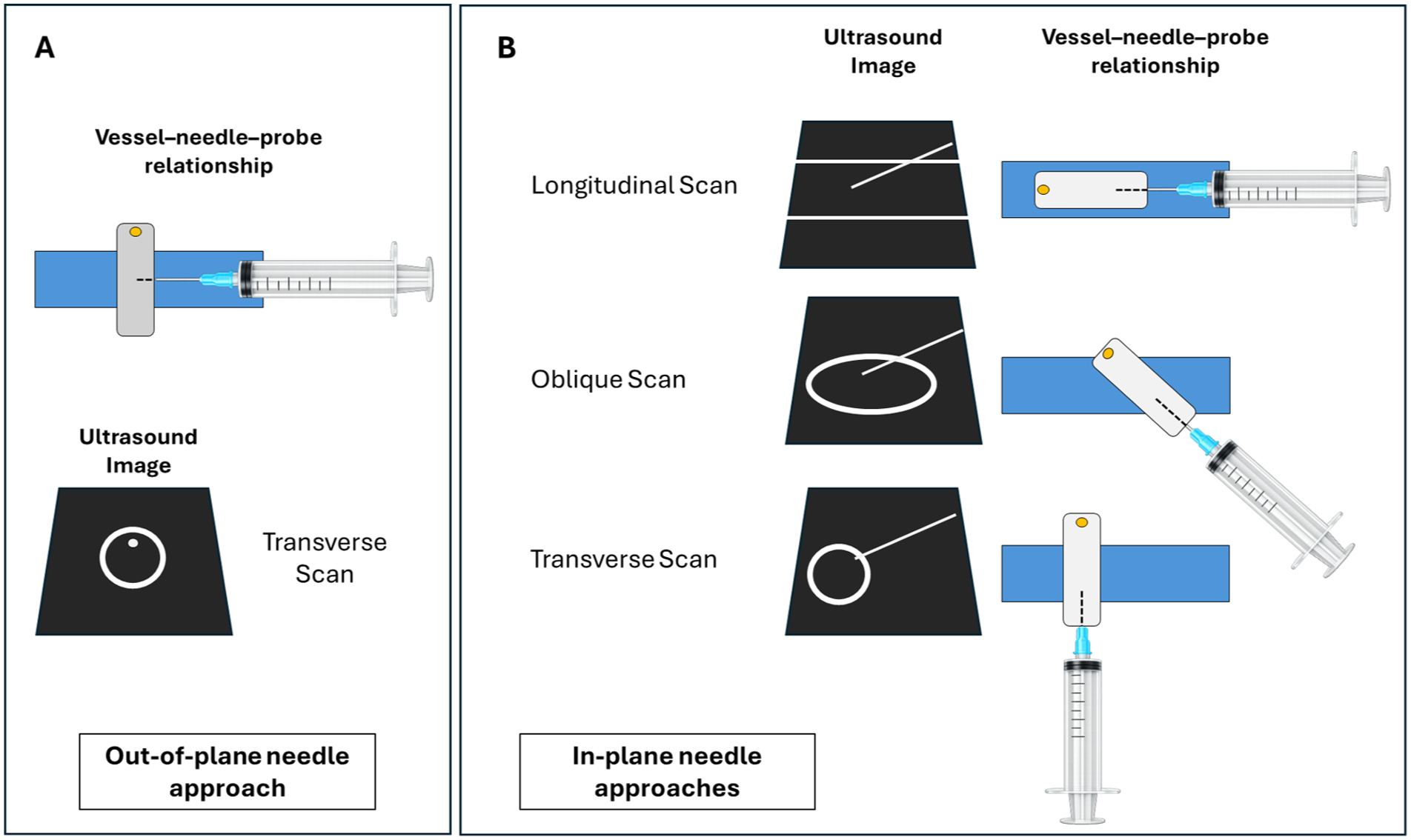
Comparison of ultrasound-guided venipuncture techniques. (A) In the out-of-plane (OOP) approach, the needle crosses the imaging plane perpendicularly and appears as a hyperechoic dot. (B) In the in-plane (IP) approach, the needle is aligned parallel to the beam, allowing longitudinal visualization of both shaft and tip. While OOP is limited to transverse scanning, IP can be performed in longitudinal, transverse, or oblique orientations, as already described by Brescia et al. 5
The IP approach is widely adopted in clinical practice because it enables continuous visualization of the needle shaft and more reliable identification of the needle tip, which is less affected by lateral resolution compared with OOP imaging.1,9 By its intrinsic geometry, the IP technique requires a shallower puncture angle, a feature that confers several procedural advantages. A reduced insertion angle improves needle visualization by increasing the perpendicular interaction between the ultrasound beam and the needle, thereby enhancing echogenicity, reduces the risk of posterior wall injury, and facilitates guidewire, dilator, and catheter advancement during the Seldinger technique. In addition, the creation of a longer pseudo-tunneling tract may contribute to a lower risk of infection, reduced endothelial trauma, decreased thrombosis, and improved catheter stability (See Figure 2).1,10–12 Finally, the IP approach has been shown to improve cannulation of veins that are particularly challenging to access using an OOP technique, such as the supraclavicular subclavian and brachiocephalic veins.
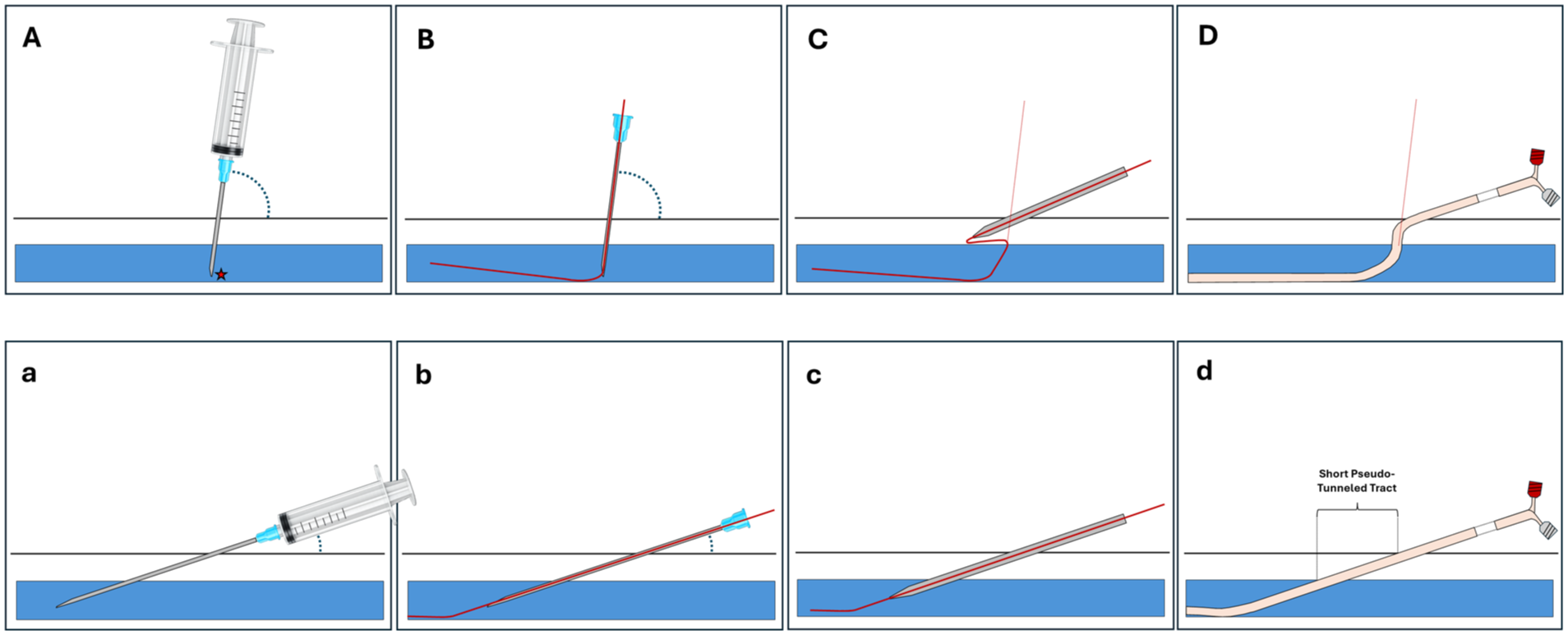
Effect of needle insertion angle during in-plane ultrasound-guided venipuncture using the Seldinger technique. Upper panels (A–D) show a steep needle insertion relative to the vessel: (A) Initial needle entry with increased risk of posterior wall puncture (★ indicates vessel wall contact); (B) guidewire advancement (red line), potentially limited by the steep angle, with risk of misdirection or vessel wall injury; (C) dilator insertion deviating from the guidewire path, resulting in creation of a false tract; (D) catheter placement with fixation at the skin entry site and an insertion angle different from that of venipuncture, resulting in a non-linear course that may partially obstruct the lumen. Lower panels (a–d) show a shallow insertion angle: (a) Initial needle entry with a longer intravascular segment, reducing posterior wall puncture risk; (b) guidewire advancement aligned with the vessel axis; (c) dilator insertion following the same trajectory as the guidewire; (d) catheter placement with formation of a short pseudo-tunneled tract and minimal curvature, improving catheter stability and reducing infectious and thrombotic risk. A shallow insertion angle improves needle visualization by optimizing interaction with the ultrasound beam, thereby enhancing procedural safety.
Despite these theoretical and practical advantages, IP guidance is affected by important technical limitations. Chief among these are the difficulty of maintaining precise alignment between the needle and the narrow ultrasound imaging plane, as well as the presence of slice thickness artefacts.8,9,13 These factors may compromise accurate needle visualization and spatial localization, potentially impairing the procedure and creating a false sense of security that can increase the risk of injury to structures adjacent to the vessel. In line with these limitations, available evidence reports conflicting results regarding the superiority of IP over OOP techniques and recent meta-analyses have shown no significant differences in first-pass success, cannulation time, number of attempts, or complication rates between the two approaches.6,7,14,15 From a clinical perspective, failure to recognize these limitations may paradoxically increase the risk of complications, underscoring the need for a critical and informed application of needle visualization techniques in routine ultrasound-guided vascular access.
Methods
This narrative review examines the mechanisms, clinical implications, and mitigation strategies of slice thickness artefact during in-plane (IP) ultrasound-guided venipuncture. Literature published up to 2026 was searched in PubMed, Scopus, and Web of Science using terms such as “in-plane ultrasound,” “vascular access,” “needle tip visualization,” and “slice thickness artefact.” Relevant experimental, clinical, and review articles were selected, with additional references identified through manual searches of citations and expert recommendations. Evidence was synthesized qualitatively to highlight underrecognized technical limitations and practical approaches to improve needle tip visualization and procedural safety. The complete literature search strategy, including MeSH terms and search domains, is provided in the Appendix.
Results
Ultrasound beam width and slice thickness artefact
Ultrasound imaging is constrained by the three-dimensional geometry of the acoustic beam. In addition to its axial and lateral dimensions, the beam has a finite elevational thickness (commonly referred to as slice thickness) which defines its extent perpendicular to the imaging plane (See Figure 3).9,16 As described by Feldman et al. and Baad et al., image formation relies on simplifying assumptions that all received echoes originate from within the central imaging plane and along the main ultrasound beam; violations of these assumptions give rise to characteristic artefacts. Slice thickness artefact, also referred to as a beam width artefact, arises from the finite width of the main ultrasound beam in the elevational dimension. Echoes generated by structures located outside the nominal imaging plane but still within the main beam are incorrectly mapped into the two-dimensional (2D) image.17,18
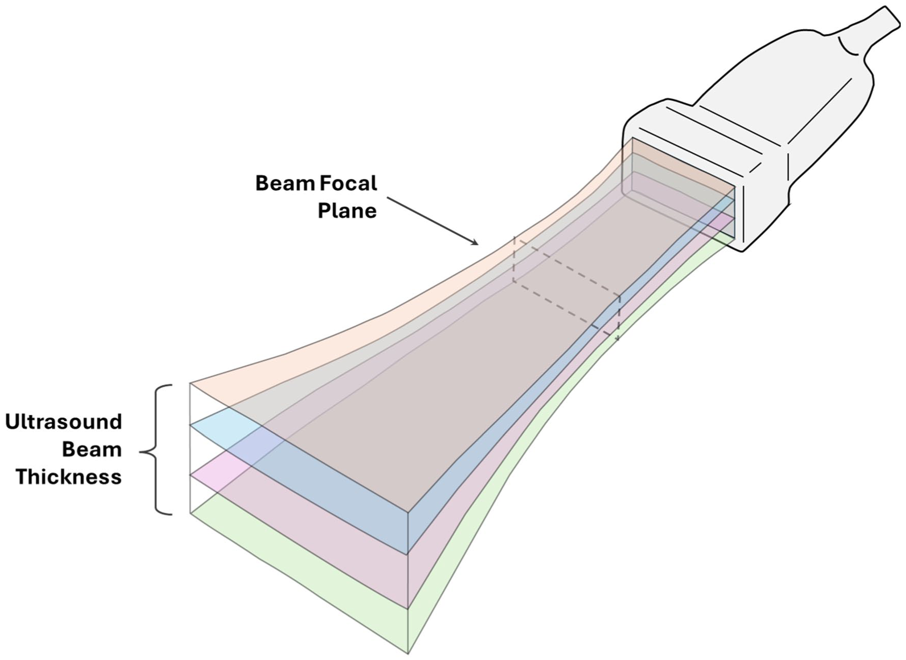
Schematic representation of the finite elevational thickness of the ultrasound beam, adapted from Scholten et al. 13 The image illustrates multiple insonated planes encompassed by the beam that collectively contribute to the two-dimensional image displayed on the monitor. Although only the central imaging plane is assumed to be visualized, echoes from adjacent parallel planes are also included, generating partial volume effects. The focal plane represents the region of maximal beam convergence, where elevational beam width is minimal and spatial resolution is highest.
During in-plane needle guidance, slice thickness artefact may cause the needle shaft or tip to appear within the lumen of the target vessel despite being positioned in a parallel but adjacent plane (See Figure 4). This apparent intraluminal position reflects inclusion of off-plane echoes within the main beam rather than true coplanarity between the needle and the imaging plane. Quantitative characterization of this phenomenon has been provided by Peikari et al., who studied elevational beamwidth artefacts during needle placement for prostate brachytherapy. Their results demonstrated that localization errors attributable to slice thickness artefact range from 0.5 to 4 mm depending on imaging parameters, providing concrete quantitative evidence of the clinical relevance of this effect. 19
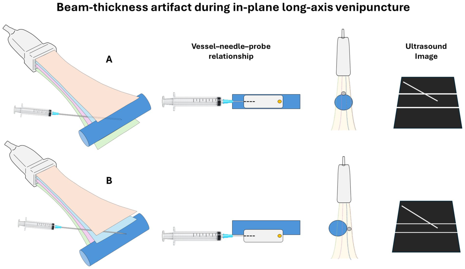
Slice thickness artefact during in-plane ultrasound-guided venipuncture. (A) Needle and vessel located within the central imaging plane of the ultrasound beam. Echoes from both structures originate from the same insonated plane and contribute correctly to the formation of the two-dimensional image. (B) Needle and vessel located within the elevational beam width but in adjacent parallel planes. Echoes from these off-plane structures are projected into the same two-dimensional image, creating a partial volume effect in which the needle appears aligned with the vessel and falsely intraluminal despite a parallel but off-plane trajectory. This phenomenon represents the slice thickness artefact and may lead to incorrect needle tip localization despite apparent continuous in-plane visualization.
Clinically, this artefact is relevant because critical structures such as arteries, nerves, or pleura may lie in planes parallel to the target vein and remain undetected, exposing them to inadvertent injury while the operator perceives correct needle alignment. Moreover, absent blood return may lead to further needle advancement under the false assumption that the vessel wall has not yet been penetrated, increasing the risk of posterior wall injury, pneumothorax during axillary access, or unintended extravascular catheter placement.
The magnitude of slice-thickness artefact is not constant and depends on several technical factors, including imaging depth, focal zone configuration, and transducer design. Beam divergence increases with depth, enlarging the elevational beam width and amplifying the contribution of off-plane echoes. This phenomenon is particularly relevant for deep veins, such as the axillary or femoral, especially when using lower-frequency probes (2–5 MHz), and may be partially mitigated by optimizing beam convergence, for example, by aligning the focal zone with the target. 20 Moreover, variations in ultrasound systems and probe types can influence the extent of slice-thickness artefact and impact the reliability of in-plane needle visualization. In a recent comparative study, Scholten et al. evaluated the beam thickness of commonly used point-of-care ultrasound devices and found substantial variability between models, even when using the same type of probe. For instance, the convex probe exhibited a focal plane thickness ranging from 2.7 to 7.3 mm, emphasizing that operators must be familiar with the specific characteristics of their device and exercise caution when interpreting imaging data. 9
Failure to recognize and adjust for these physical limitations may partly explain the lower first-pass success rates, longer cannulation times, and higher number of needle redirections reported for in-plane guidance compared with short-axis dynamic needle tip positioning (DNTP) approaches in some clinical studies. 6 Importantly, a randomized trial demonstrated that reducing elevational beam width through the use of an acoustic lens significantly improved first-pass success during superficial in-plane vascular access (92.5% vs 68.7%, p < 0.001) providing direct evidence that slice thickness artefact represents a clinically meaningful and modifiable source of procedural error. 13
Error reduction strategies
Several strategies have been proposed to reduce errors related to slice thickness artefact during in-plane (IP) ultrasound-guided venipuncture. Some of these measures are supported by experimental or clinical evidence, whereas others rely primarily on expert consensus and practical experience. Careful recognition and systematic study of slice thickness artefact are essential, as they not only inform the effective implementation of current mitigation strategies but also guide future research aimed at optimizing ultrasound-guided vascular access and minimizing procedural complications.
To minimize slice thickness–related errors, operators should adopt the following strategies.
Beam width awareness. Operators should recognize that continuous needle visualization does not guarantee true coplanarity.1,8 Understanding this limitation prevents overconfidence and encourages careful verification of needle tip position throughout the procedure.
Ultrasound system and beam profile knowledge. Operators should be familiar with the elevational beam characteristics of the specific ultrasound system and transducer in use.1,9 Awareness of the expected slice thickness at the target depth allows more accurate interpretation of in-plane needle images and reduces misjudgment of true needle–vessel alignment, particularly when using handheld or low-frequency devices, or when cannulating small-caliber and deep vessels.
Selection of the most superficial vein (depth optimization). Whenever feasible, selecting a more superficial vascular access reduces imaging depth and, consequently, beam divergence, thereby improving lateral and elevational resolution and enhancing accurate needle tip visualization. 21
Probe selection. Choosing transducers with thinner elevational beams can reduce slice-thickness artefacts, particularly for superficial vessels.9,22 The American Society of Echocardiography recommends high-frequency linear probes (8–12 MHz) for vascular access whenever feasible. 1 However, in patients with deeper vessels, such as those with obesity, lower-frequency probes with higher penetration (2–5 MHz, e.g. convex) may be necessary despite their larger beam thickness. With convex probes, the lower frequency and fan-shaped field geometry result in greater beam divergence at depth, amplifying slice thickness artefact and requiring enhanced dynamic probe manipulation to maintain optimal needle visualization. 2 Supplemental Video 1 illustrates a venipuncture in an obese patient where slice-thickness artefact was significant, and multiple strategies were applied to successfully position the catheter.
Focal zone placement at target depth. Aligning the focal zone with the vessel ensures optimal beam convergence, minimizing artefactual needle images and improving vessel wall definition. 20
Dynamic probe movement to optimize needle–ultrasound–vessel alignment. Subtle tilting or sliding of the transducer allows confirmation that the needle remains within the intended imaging plane, offering multiple perspectives on the needle–vessel relationship and reducing misinterpretation due to superimposed echoes. 8
Central axis alignment. Directing the needle toward the vessel’s central axis, as emphasized in current guidelines, may reduce the risk of false tip localization and potentially enhance procedural safety. 1 In longitudinal scans, the vessel center usually corresponds to the region with the largest diameter and the most clearly resolved vessel walls, facilitating safer cannulation.
Controlled needle advancement. A systematic approach to needle advancement, such as the Probe Needle Technique (PN-T) and the Three Stations of the Needle framework described by Ostroff and Moureau, can enhance procedural safety by dividing the needle trajectory into three distinct phases: (1) picking up the needle tip in the tissue, (2) guiding the needle to the wall of the vein, and (3) puncturing the vessel. 23 At each station, ultrasound should be used to actively identify the needle tip and confirm its alignment with the target imaging plane before further advancement; progression should be halted whenever tip visualization becomes uncertain. 24 This stepwise approach is particularly valuable in the presence of slice thickness artefact, as deliberate pauses at each phase allow verification of true needle–vessel coplanarity, reducing the risk of inadvertent injury to posterior or adjacent structures.
Backflow confirmation. Consistently verifying venous blood return when the tip appears in the vessel complements visual guidance and helps identify false-positive tip positions caused by slice thickness artefact. If blood return is absent, operators should consider that the needle may be in a parallel plane rather than assuming incomplete venous penetration, avoiding advancement that could damage posterior structures. The ASE 2025 and ASE/SCA 2011 guidelines note that backflow verification, in addition to direct needle visualization, can support confirmation of vascular cannulation and enhance procedural safety.1,25
Complementary OOP verification. Briefly switching to an out-of-plane view can confirm needle–vessel relationships, particularly for deep, tortuous, or angulated veins. Meta-analyses and guidelines, including the Society of Critical Care Medicine, support complementary use of short- and long-axis views, with scan orientation guided by patient anatomy, operator experience, and local anatomy to optimize procedural safety and effectiveness.26,27
Acoustic lens usage. The application of acoustic lenses reduces slice thickness and enhances needle tip accuracy, as demonstrated in clinical studies. 13
Although some strategies have strong supporting evidence, most rely on operator expertise and situational judgment. Prospective studies are needed to quantify their effectiveness in improving procedural safety.
Conclusion
In-plane ultrasound guidance improves needle visualization but does not guarantee accurate needle tip localization when ultrasound beam geometry is overlooked. Slice thickness artefact is a frequent and underrecognized source of false intraluminal appearance that can compromise procedural safety. Awareness of this limitation and application of targeted mitigation strategies are essential not only for vascular access but for all ultrasound-guided procedures using an in-plane technique, particularly with deep targets and handheld or low-frequency devices.
Footnotes
Appendix
Declaration of conflicting interests
The authors declared no potential conflicts of interest with respect to the research, authorship, and/or publication of this article.
Funding
The authors received no financial support for the research, authorship, and/or publication of this article.
Informed consent
Written informed consent for the use of patient images and video was obtained.
Supplemental material
Supplemental material for this article is available online.
References
Supplementary Material
Please find the following supplemental material available below.
For Open Access articles published under a Creative Commons License, all supplemental material carries the same license as the article it is associated with.
For non-Open Access articles published, all supplemental material carries a non-exclusive license, and permission requests for re-use of supplemental material or any part of supplemental material shall be sent directly to the copyright owner as specified in the copyright notice associated with the article.