
Abstract
Background:
Conventional electromagnetic dampers impose a bias torque on artillery systems, which adversely affects system stability and performance.
Objective:
This study aims to propose a novel concentric electromagnetic damper (C-EMD). Based on the principle of electromagnetic induction, it achieves efficient braking to effectively eliminate the aforementioned bias torque effect.
Methods:
First, a nonlinear dynamic model of the C-EMD was established through theoretical analysis, finite element simulations, and impact experiments. This model was used to analyze the mechanism by which magnetic flux density affects damping performance and the parameter influence patterns. Subsequently, parameter sensitivity analysis was conducted using Optimal Latin Hypercube Design (OLHD) and polynomial regression methods. Finally, a surrogate model based on elliptic basis neural networks was developed, and multi-objective optimization was performed by integrating multi-island genetic algorithms with nonlinear programming by quadratic lagrangian.
Results:
Modeling analysis revealed that the resultant resistance curve exhibits a saddle-shaped profile with a concave center and elevated ends. Parameter sensitivity analysis results showed that liner thickness and air gap thickness have the most significant impact on performance (contributions >26%), while the influence of outer tube thickness is minimal (only 0.83%). Post-optimization results demonstrated: a reduction in resultant resistance curve flatness to 1.42, an increase in fill ratio to 89.86%, a 4.63% decrease in maximum displacement, and near-complete elimination of the saddle-shaped characteristics.
Conclusions:
This research provides an innovative solution for enhancing electromagnetic damper performance, with significant practical implications.
Keywords
Introduction
An electromagnetic damper is an energy-dissipation device designed based on electromagnetic induction principles, with permanent magnets and conductors constituting its core components. Compared to viscous dampers, it eliminates concerns about sealing leakage and fluid replenishment in working media while offering minimal frictional wear, leading to broad applications in vehicle vibration reduction1,2 and building seismic resistance.3–5 In recent years, the emergence of high-performance NdFeB materials has significantly enhanced its energy dissipation density. Furthermore, electromagnetic dampers demonstrate advantages including non-contact operation, structural simplicity, and high reliability, driving increasing research in impact load scenarios such as weapon launching,6,7 alongside rapid developments in modeling methodologies.
To address different configurations and application scenarios of permanent magnets, researchers have developed various eddy-current modeling theories. For example, Park et al. 8 established a two-dimensional analytical model for Halbach-array eddy-current brakes using magnetic vector potential theory, validating the accuracy of braking torque calculations through finite element simulations and rotational speed-torque experiments, while analyzing critical parameter effects on braking performance. Min et al. 9 employed a vector potential polar coordinate method to theoretically resolve eddy-current losses in Halbach-array magnetic couplers, combined with finite element verification to investigate segmentation effects on loss characteristics. Tian et al. 10 proposed an efficient magneto-thermal coupling model for eddy-current brakes, simplifying electromagnetic field computations into mapping relationships between braking torque and stator skin-layer temperature, thereby significantly reducing computational costs. Their study revealed that optimizing thermal properties of stator materials enhances braking torque.
Research on artillery applications of electromagnetic dampers primarily employs theoretical analysis, numerical simulation, and experimental validation. Li et al. 11 investigated a high-energy density electromagnetic buffer (EMB). Based on design requirements, magnetic circuit parameters were determined. The equivalent current model was employed to analyze eddy current characteristics under demagnetization effects, while a segmented conduit strategy was adopted to resolve magnetization processes. Experimental validation confirmed the finite element results, demonstrating that the proposed EMB effectively accomplishes impact buffering. Li et al. 12 developed a novel permanent magnet linear eddy-current damper, constructing an improved equivalent magnetic circuit model based on magnetic field modulation theory. This model notably improved prediction accuracy for air-gap magnetic flux density and damping forces by comprehensively considering magnetic saturation effects, skin depth, and end effects. Li et al. 13 introduced an equivalent subdomain method combining subdomain analysis and equivalent magnetic circuit modeling to calculate performance parameters of permanent magnet eddy-current dampers, establishing a prototype test platform to validate method effectiveness through experiments and finite element analysis. Shen et al. 14 investigated the influence of different magnetic circuit configurations on braking performance, proposing a concentric recoil system design integrating eddy-current dampers with gun barrels, and analyzing parameter effects on recoil control characteristics. Liu et al. 15 utilized equivalent subdomain models to study magnetic field behavior in permanent magnet eddy-current dampers under intense impact loads, developed time-varying finite element models to simulate operational processes, and designed a scaled prototype measurement system for dynamic magnetic field characterization under intensive impact conditions.
The Jiles-Atherton (J-A) model is a classical framework for characterizing hysteresis properties of ferromagnetic materials, capable of simultaneously describing macroscopic magnetization behavior and microscopic energy loss mechanisms. Research based on this theory and its improved variants has become an important approach for analyzing the nonlinear hysteresis characteristics and loss mechanisms of ferromagnetic materials. To elucidate demagnetization and damping mechanisms of permanent magnets under intensive impact loads and elevated temperatures, Li et al. 16 proposed a modified exponential demagnetization model to simulate the demagnetization process of NdFeB permanent magnets, coupled with an improved vector hysteresis model accounting for hysteresis effects in soft magnetic materials. Li et al. 17 systematically investigated demagnetization models of NdFeB permanent magnets and their application in eddy-current dampers, obtaining J-A model demagnetization curves for NdFeB at varying temperatures through experimental data fitting. Peng et al. 18 developed a torque-adjustable bilateral axial-flux permanent magnet hysteresis damper, innovatively employing a modified vector J-A hysteresis model to precisely simulate flux distribution and hysteresis torque. Prototype validation demonstrated the model's high computational accuracy in characterizing hysteresis effects. Zheng et al. 19 introduced an improved micromagnetic simulation method incorporating spatiotemporal correction coefficients for large-grain magnetic materials. Using sintered NdFeB as a case study, equivalent calculations based on thermal demagnetization theory yielded simulated results in excellent agreement with experimental thermal demagnetization curves.
Performance optimization of electromagnetic dampers in artillery systems is critical, with core objectives centered on precise control of barrel recoil and counter-recoil motion. Li et al. 20 proposed an analytical method for electromagnetic field calculation in tubular linear permanent magnet eddy current brake. By solving boundary value problems using Fourier series expansion and variable separation techniques, the approach was validated against finite element analysis. To enhance braking performance within spatial constraints, parametric analysis identified feasible design ranges, followed by multi-objective optimization to determine optimal parameters. The optimized design achieved a 27% increase in braking force while reducing permanent magnet volume by 7.7%. Li et al. 21 presented a robust design methodology for electromagnetic dampers based on interval uncertainty optimization. Through sensitivity analysis using Optimal Latin Hypercube Design and polynomial regression, key parameters were screened to establish a resultant resistance force (RRF) considering robustness interval uncertainty optimization model. A radial basis function neural network-based interval nested optimization algorithm was developed to efficiently solve Pareto frontiers, with numerical simulations confirming the effectiveness of optimization objectives and strategies. Xu et al. 22 addressed peak recoil resistance optimization by proposing a segmented optimization scheme considering parameter uncertainties via robust game theory. A novel robust Nash equilibrium solution method was developed through affine arithmetic and Chebyshev polynomial-based deep integration, mitigating electromagnetic damping force fluctuations caused by uncertainties. Optimized inner/outer tube thicknesses significantly reduced peak recoil resistance. Liu et al. 23 investigated dynamic characteristics and structural optimization of linear eddy-current dampers under artillery firing loads, elevating recoil resistance curve fill ratio from 84.93% to 92.1%.
In artillery systems, conventional electromagnetic dampers are typically installed in a non-coaxial configuration relative to the gun barrel. The resulting eccentric moment deteriorates the launch mechanical environment, increases muzzle disturbance, and consequently affects firing stability. The typical structural arrangement and positioning of such eccentric electromagnetic dampers within a full artillery system can be referred to in Fig. 2 of Reference 7 and Fig. 22 of Reference. 24 Xie et al. 25 comparatively studied the influence of concentric versus eccentric damper configurations on muzzle vibration. Based on an established artillery launch dynamics model, their simulation analysis demonstrated that a concentric layout effectively reduces muzzle angular displacement and angular velocity, thereby helping to mitigate muzzle disturbance and improve firing accuracy. Building on this analysis, this study proposes a novel concentric electromagnetic damper. This concentric design not only improves space utilization, allowing for a more compact lateral layout, but also ensures that loads are transmitted along the axis. This effectively eliminates the eccentric moment caused by an offset configuration, thereby reducing muzzle disturbance during firing. Furthermore, this paper establishes a nonlinear dynamic model of the proposed damper. An intensive impact experimental platform was constructed for prototype validation, complemented by transient electromagnetic finite element simulations to analyze damping characteristics and parametric influence mechanisms. Combined optimization algorithms were implemented to control dynamic responses and enhance damping performance under intense impact loads, providing theoretical foundations and practical solutions for optimized electromagnetic damper design.
Nonlinear dynamics modeling for C-EMD
Principle and configuration of the C-EMD
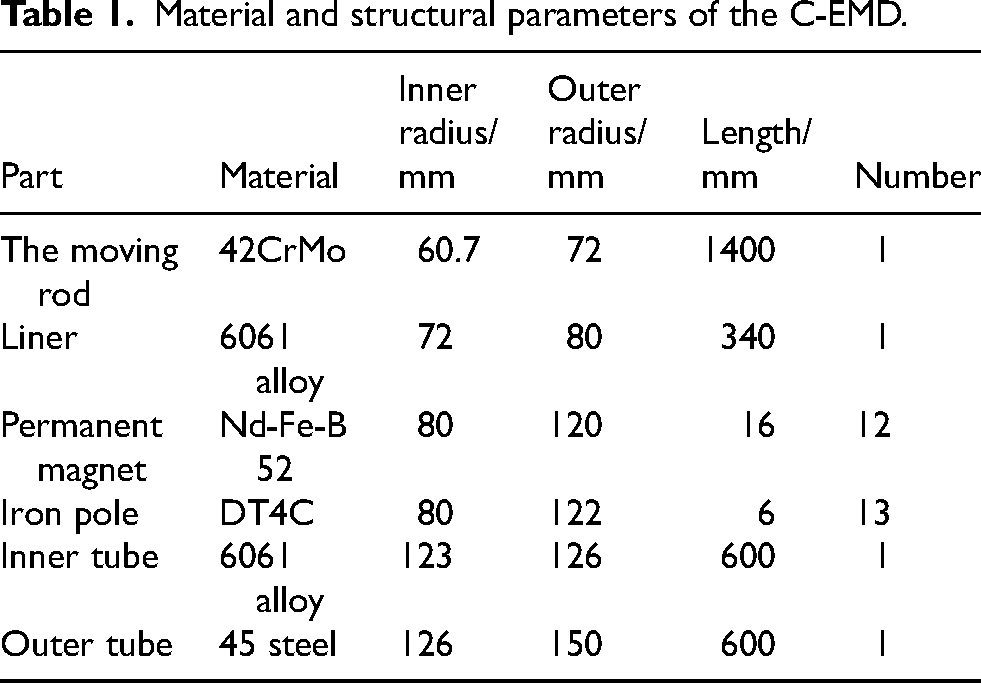
The two-dimensional structure of the concentric electromagnetic damper (C-EMD) adopted in this study is illustrated in Fig. 1, featuring a compact design where the permanent magnet assembly is coaxially fixed to the moving rod. The device comprises two primary components: a mover and a stator. The mover consists of a moving rod, liner, permanent magnets, and iron poles, while the stator is formed by a composite structure with an inner conductive tube and outer ferromagnetic tube. The inner tube utilizes 6061 aluminum alloy for its superior machinability, where high electrical conductivity generates eddy currents that impose damping forces on the mover to achieve energy dissipation. The outer tube employs 45 steel, whose ferromagnetic properties enhance magnetic field utilization and improve damping performance. Detailed structural parameters are provided in Table 1.
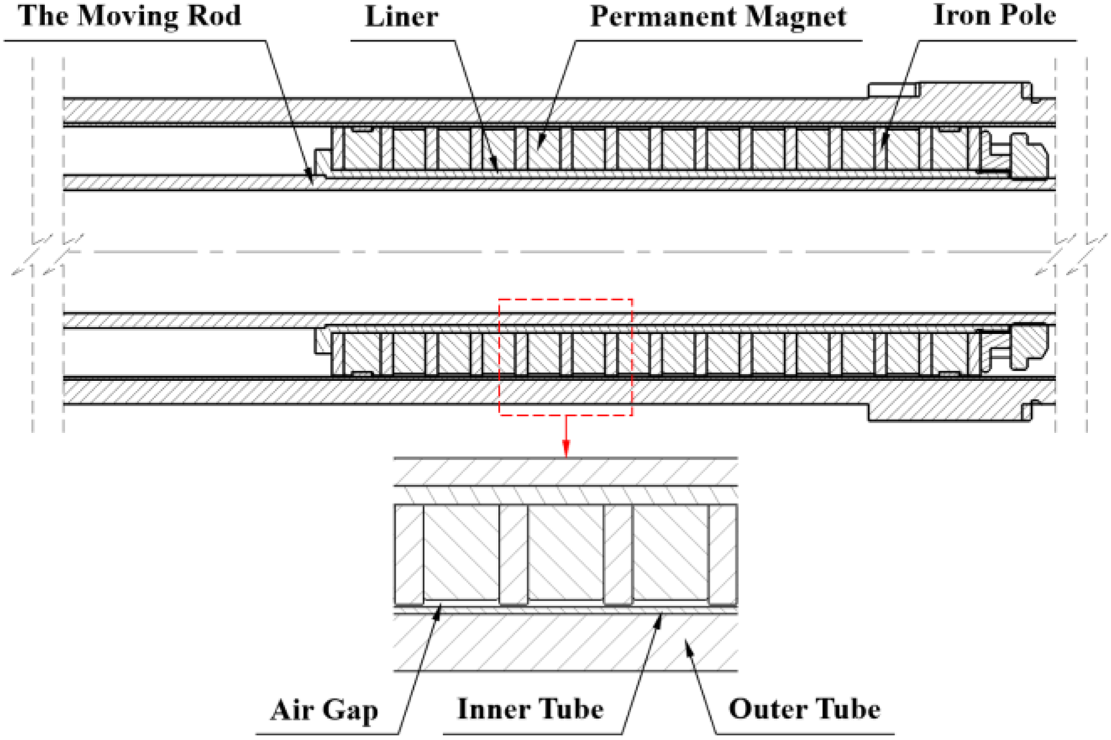
Schematic diagram of the C-EMD.
Material and structural parameters of the C-EMD.
The C-EMD operates based on Faraday's law of electromagnetic induction and Lenz's law: Relative motion between the mover and stator induces eddy currents within the inner tube. These eddy currents generate opposing magnetic fields that interact with the original field, producing damping forces counteracting the motion direction. This mechanism converts transient intensive impact loads into prolonged and smoothed loading profiles, stabilizing the recoil and counter-recoil process of the mover and enhancing the resistance plateau effect. Furthermore, as shown in Fig. 2, adjacent permanent magnets are arranged in an opposing-polarity configuration to enhance magnetic field utilization and damping performance. Their length is
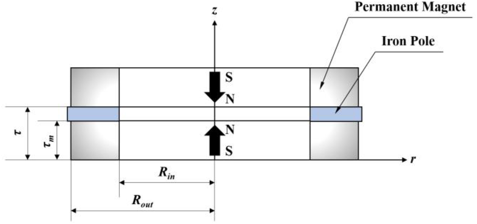
Schematic diagram of cylindrical permanent magnets in homopolar opposing configuration.
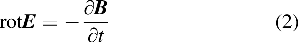
Electromagnetic field modeling of the C-EMD shown in Fig. 1 is performed based on the differential form of Maxwell's equations: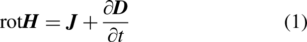


Additionally, the constitutive relations governing the physical quantities in the medium are expressed as:


The magnetic insulation boundary conditions are imposed as:
Based on the Lorentz force equation, the electromagnetic damping force generated by the inner and outer tubes cutting magnetic flux lines can be expressed as: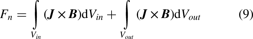
Jiles and Atherton26,27 proposed the hysteresis Jiles-Atherton model for ferromagnetic materials based on energy variations induced by pinning effects: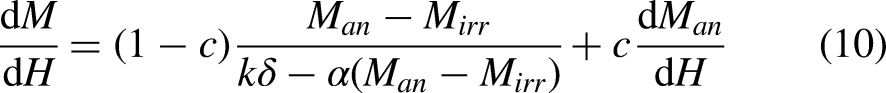
Once the five key parameters—saturation magnetization 

Under a given magnetic field intensity, the reversible component reduces the difference between the irreversible magnetization and the anhysteretic magnetization 
Based on ferromagnetic material magnetization theory, the magnetization behavior can be described by the Langevin function: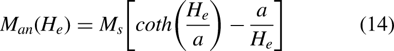

In the Jiles-Atherton hysteresis model, the reversible and irreversible magnetization components are governed by the following differential equations: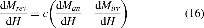
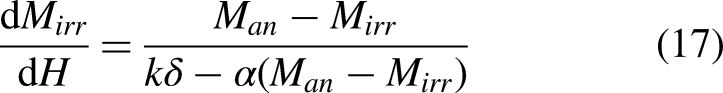
Based on the theoretical framework described above and neglecting the influence of temperature variations, mechanical vibrations, and other external factors, this study employs the finite element analysis software COMSOL Multiphysics® to simulate the dynamic response of the C-EMD. Given the rotationally axisymmetric geometry of the damper, a two-dimensional (2D) axisymmetric electromagnetic finite element model (Fig. 3) was developed to balance computational accuracy and efficiency. Components with negligible impact on the magnetic field were omitted in the model. Material properties and structural parameters in the simulation strictly adhere to the configurations listed in Table 1, ensuring consistency with experimental conditions.
Finite element model of the C-EMD.
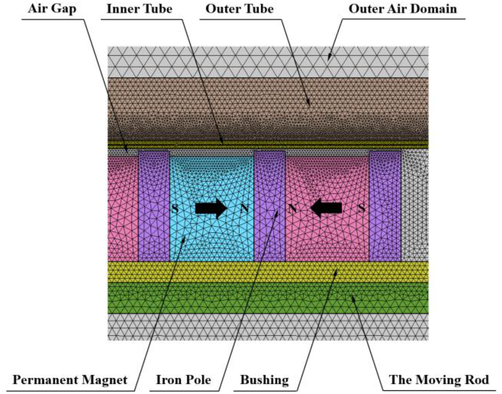
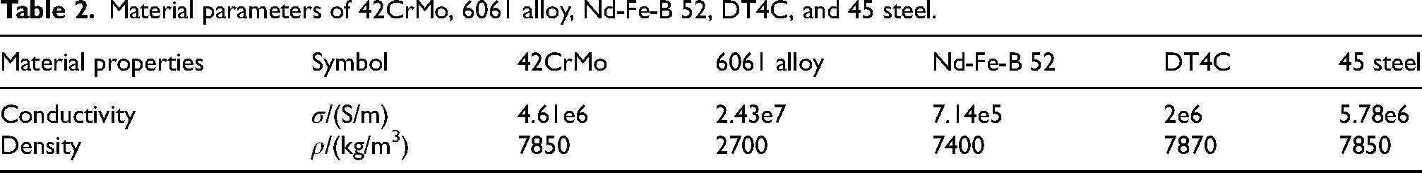
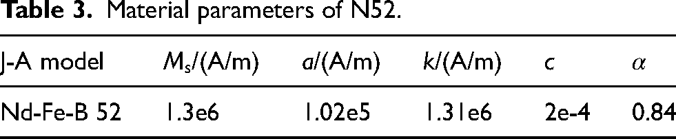
In the model, material properties and parameters were assigned to each domain, followed by the addition of relevant physics interfaces. The material properties in the simulation model are shown in Table 2, with a relative permittivity of 1 for all materials. Magnetic insulation boundary conditions were imposed, and the permanent magnet characteristics were defined using the hysteresis Jiles-Atherton model with parameters referenced from literature. 17 The temperature was 293.15 K and the initial magnetization was 1.15 × 10⁶A/m, as specified in Table 3. The homopolar opposing magnetic circuit design was implemented by specifying the positive/negative of the initial magnetization intensity. To accurately characterize the electromagnetic damping force, the magnetic saturation characteristics of the iron pole is described using the curve shown in Fig. 4. This approach, which neglects magnetic hysteresis while accounting for nonlinear characteristics, offers a favorable trade-off: it incurs a minimal loss in computational accuracy while significantly enhancing computational efficiency. Experimentally measured intensive impact loading profiles were imported as input variables, motion process variables were defined, and the global ordinary differential equations (ODEs) of motion were solved via the moving mesh method. Triangular meshing was adopted, with local mesh refinement applied to the air gap and inner tube regions to mitigate skin effect-induced errors. The total mesh count was 1.32 × 10⁵ elements with an average element quality of 0.91. Steady-state simulation results served as initial conditions for transient analysis. A time step of 5 × 10⁻⁵ s was set for the 0.035 s simulation duration. Solver configurations were optimized for transient analysis, and numerical computations yielded electromagnetic field and dynamic response results under intense impact loading.
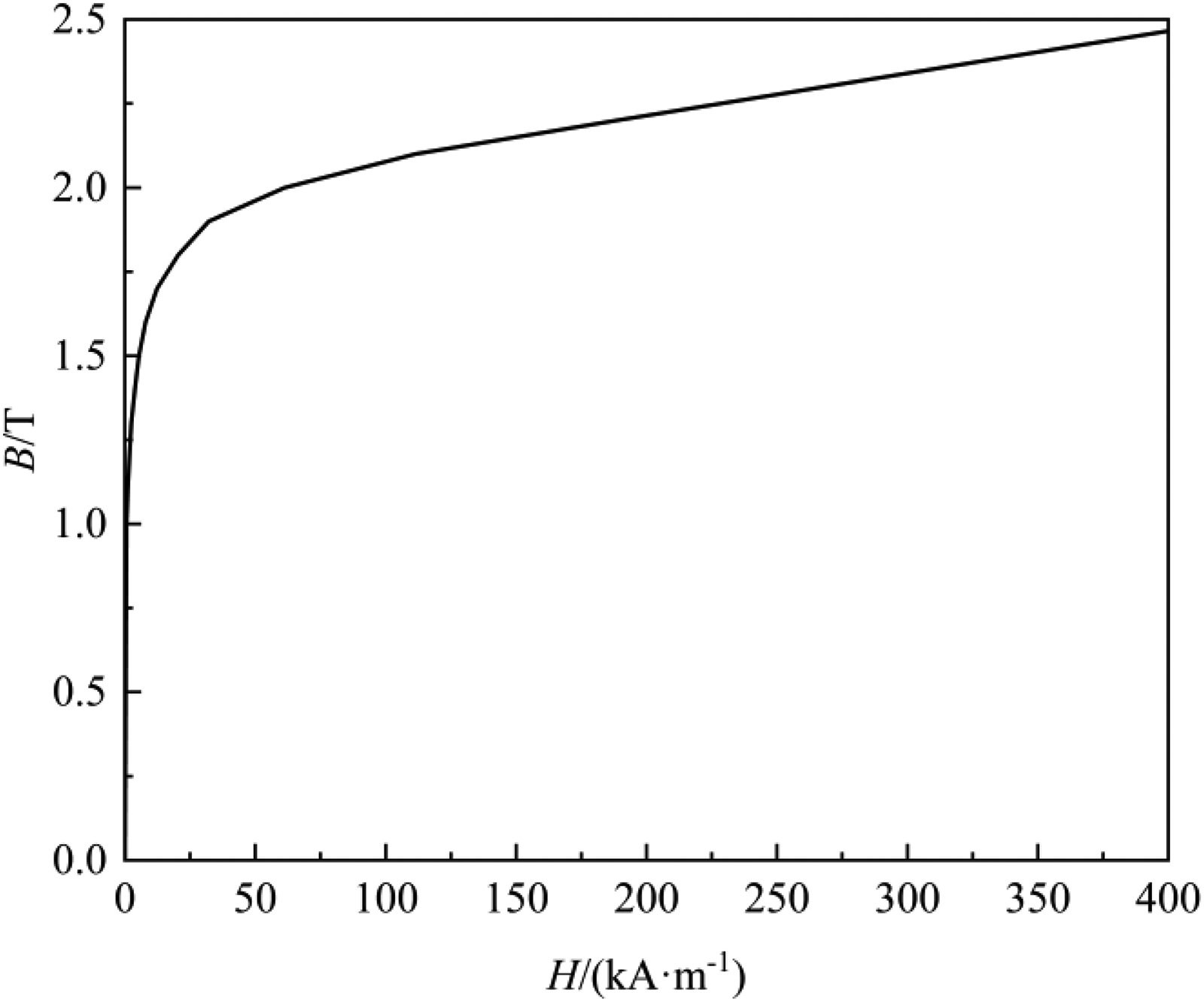
B–H curve of the iron pole.
Material parameters of 42CrMo, 6061 alloy, Nd-Fe-B 52, DT4C, and 45 steel.
Material parameters of N52.
During the motion of the C-EMD, the system is subjected to electromagnetic damping forces, counter-recoil forces, and frictional forces. These three forces collectively constitute the resultant resistance 
The counter-recoil force, generated by a spring, acts as a restoring force to return the mover to its initial position after the damping stroke. It exhibits a linear relationship with displacement, as shown in Fig. 5, and is calculated by:
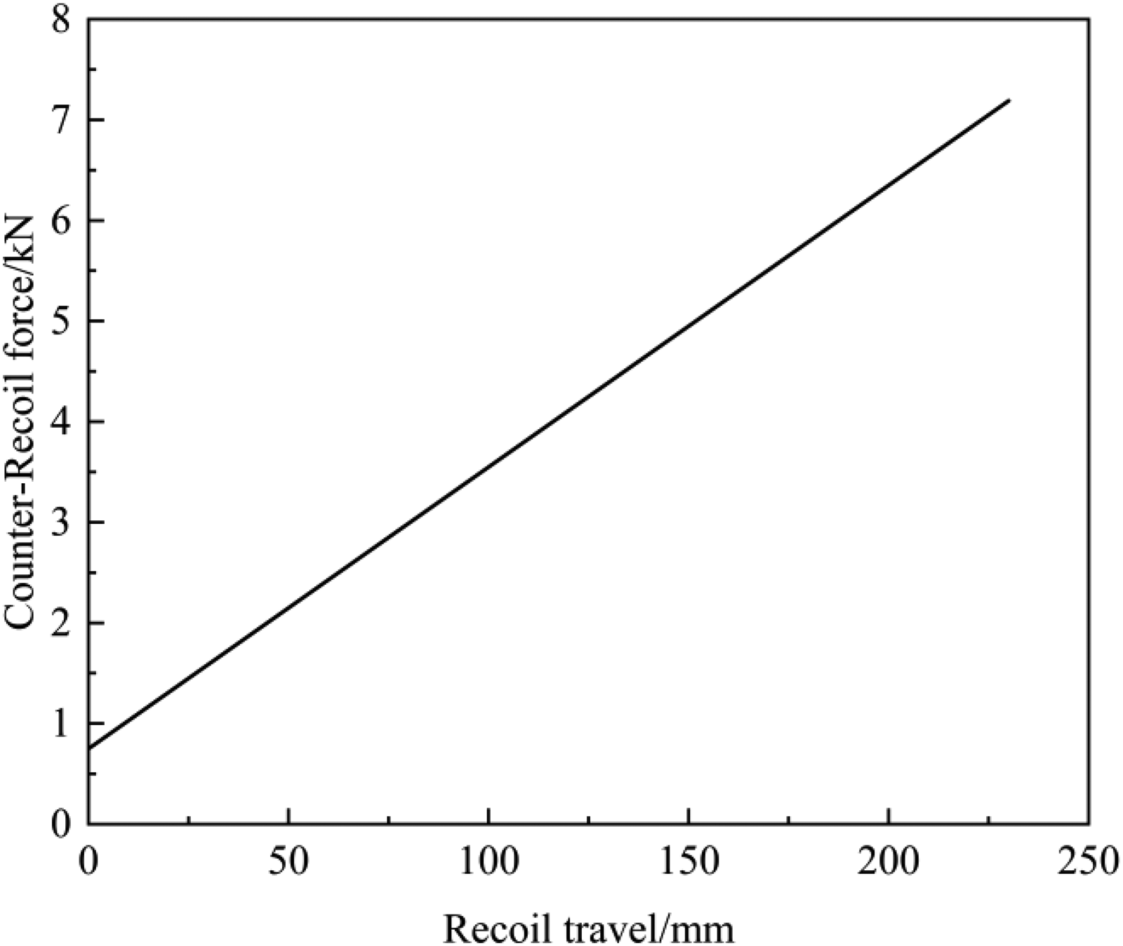
Counter-Recoil force.
The governing differential equation for the damper's motion is: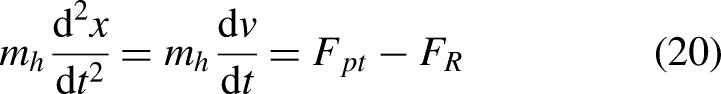
Concentric electromagnetic damper impact tests
Experiments were conducted using the C-EMD test bench shown in Fig. 6, which primarily consists of a projectile, composite tube, permanent magnet assembly, moving rod, frame, and spring. The permanent magnet assembly, spring, and moving rod are coaxially arranged, with this concentric configuration eliminating bias torque effects on the artillery system. The composite tube and frame form the stator, fixed to the test bench, while the moving rod, spring, and permanent magnet assembly constitute the mover. Under intensive impact loading, the projectile is launched along the moving rod, inducing relative motion between the mover and stator. This generates eddy currents in the composite tube, producing damping forces to counteract the mover's motion and achieve braking. The spring compresses to store energy during recoil and restores its original length during counter-recoil, providing restoring forces to reset the mover and complete the recoil and counter-recoil cycle.
Test bench platform for the C-EMD.
The dynamic test system for the C-EMD (Fig. 7) includes a displacement sensor, acceleration sensor, force sensor, charge amplifier, and data acquisition system. The displacement sensor is fixed directly behind the damper, while the acceleration sensor and force sensor are mounted on the breech. Upon ignition trigger initiation, the mover completes one recoil and counter-recoil cycle under impact loading. The displacement sensor outputs voltage signals directly to the data acquisition system, whereas charge signals from the acceleration sensor and force sensor are converted to voltage signals via the charge amplifier before being recorded, with a sampling frequency of 200 kHz. The data acquisition system processes these signals into displacement, acceleration, and pressure data, with velocity derived by differentiating displacement. Specifications of the sensors are listed in Table 4.
Dynamic testing system of the C-EMD.
Type and performance parameters of the sensors.
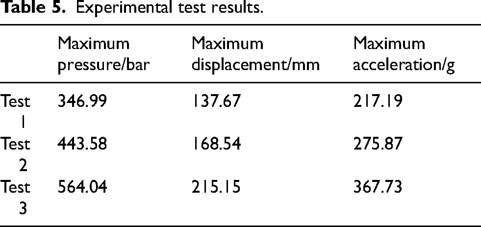
Test results for three experimental trials are summarized in Table 5, revealing significant differences in mover dynamics under varying peak impact loads. With an increase in the charge mass, the maximum pressure rises correspondingly, which consequently and directly leads to synchronous increases in both the maximum displacement and maximum acceleration of the mover. The recoil and counter-recoil process for Experiment 1 (Fig. 8) demonstrates complete operational reliability: the mover attains a maximum displacement of 137.67 mm within 31.43 ms before fully resetting. Smoke dispersion is visibly observed during reset (Fig. 8(d)). Measured impact load curves for all three trials (Fig. 9) exhibit peak values of 97.32 kN, 127.09 kN, and 159.2 kN, respectively, characteristic of high-transient, intense impact loading.
Mover recoil and counter-recoil process.
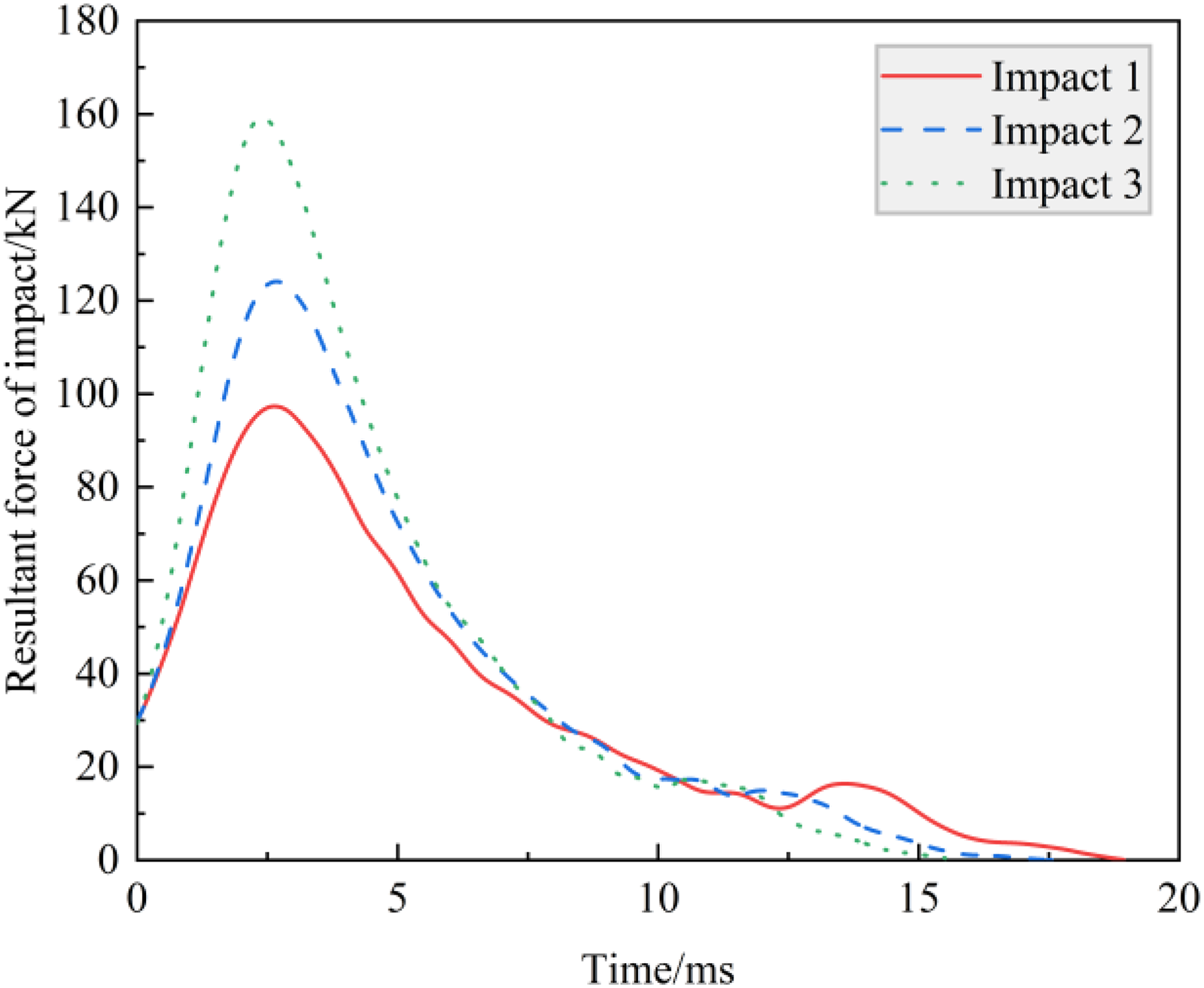
Intensive impact loads.
Experimental test results.
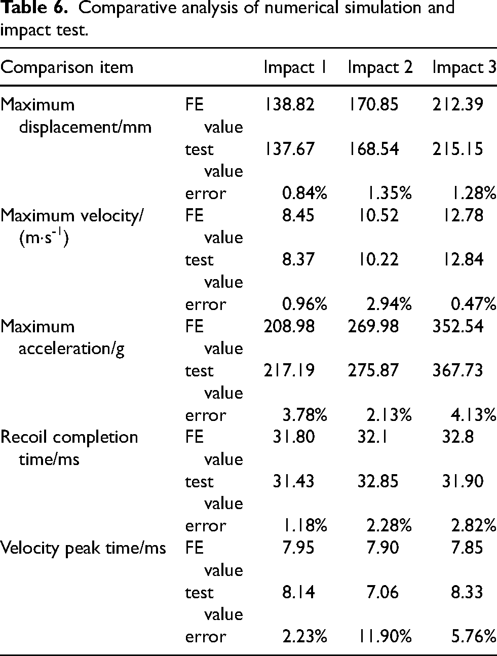
As shown in Fig. 10, the displacement, velocity, and acceleration curves of the concentric electromagnetic damper's nonlinear dynamic model under three distinct impact loads exhibit excellent agreement with experimental measurements. Key metrics—including maximum displacement, maximum velocity, maximum acceleration, recoil completion time, and velocity peak timing—align closely with finite element method (FEM) results, with minimal errors (Table 6). This validates the simulation model's capability to accurately characterize the dynamic response of the C-EMD. Furthermore, the model and simulation methodology can be employed to analyze the influence of varying impact loads on damping performance and optimize the structural design of the C-EMD.
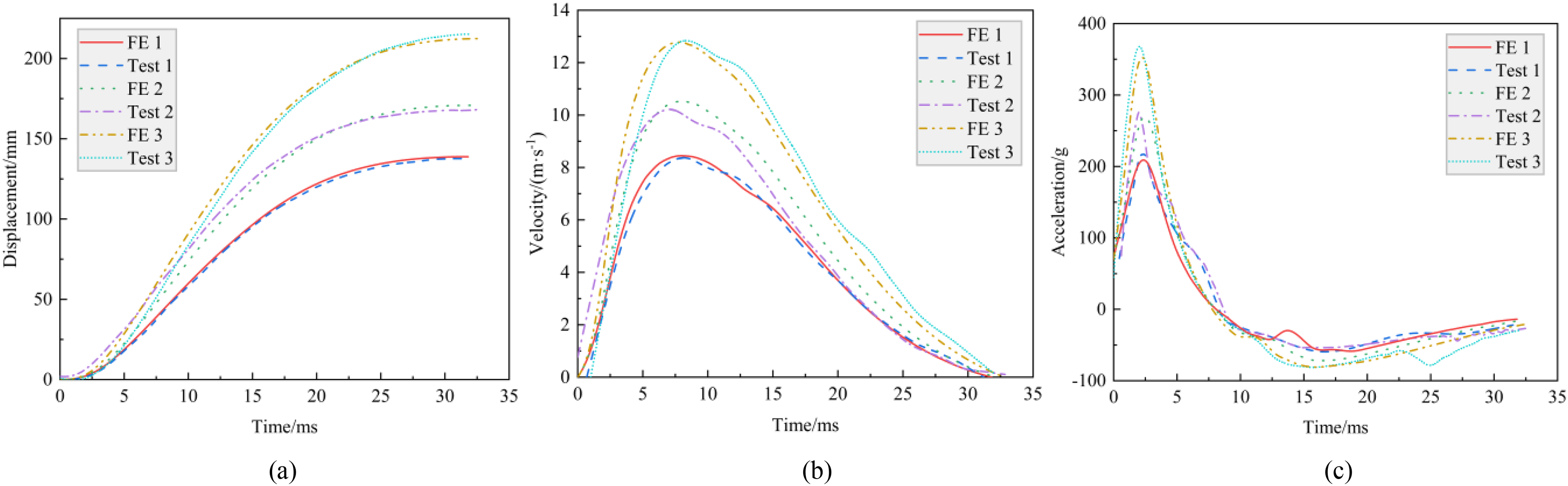
Simulation and experiment comparison curves (a) displacement - time, (b) velocity - time, (c) acceleration – time.
Comparative analysis of numerical simulation and impact test.
The damping coefficient, a critical parameter for evaluating the damping performance of electromagnetic dampers, quantifies the braking effectiveness and can be expressed as
28
:
Selecting the inner tube of the C-EMD as the integration domain, the calculated C values under three distinct impact loads are illustrated in Fig. 11. At
Damping coefficient-time curve.
Damping coefficient-velocity curve.
A region spanning four times the pole pitch at the median diameter position of the inner tube was selected to analyze magnetic field variations under different impact loads. Figure 13 illustrates the temporal evolution of radial magnetic flux density at this location. Influenced by the permanent magnet arrangement and the flux-conducting properties of the iron poles, a periodic traveling-wave magnetic field is formed, with maximum radial magnetic flux density occurring at the iron poles and opposite magnetic flux density directions observed between adjacent iron poles. At t = 0, the magnetic field stabilizes, and the magnetic flux density curve exhibits an approximately symmetric distribution about the center of the iron poles, peaking at 1.74 T. At
Radial magnetic flux density at the median diameter of the inner tube.
Analysis of parameters affecting damping performance
The influence of structural parameters on the damping performance of the C-EMD system manifests in two primary aspects: the parametric dependence of electromagnetic damping forces and the spring stiffness effects on counter-recoil forces. Under constant permanent magnet parameters, a single-variable control method was employed to investigate seven independent parameters—liner thickness, axial length of iron pole, iron pole wall thickness, air gap thickness, inner tube thickness, outer tube thickness, and spring stiffness—on damping characteristics. Given the high velocity of the mover during recoil, these parameters significantly affect dynamic behaviors, making the resultant resistance force (RRF) during recoil the focal metric for analysis. To ensure controlled variables, experimentally validated impact load data from Test Case 1 (with minimal error) was adopted as the input.
During recoil, the C-EMD is subjected to combined electromagnetic damping, counter-recoil, and frictional forces, collectively forming the saddle-shaped resultant resistance force shown in Fig. 14. Analysis of Test Case 1 reveals two distinct resistance peaks (
Schematic diagram of the RRF curve.
The influence of seven independent parameters on the resultant resistance force versus recoil displacement characteristics is illustrated in Fig. 15, with subplots (a)-(g) corresponding to parametric analyses of liner thickness (
Influence of different parameters on the resultant resistance force-recoil travel curve.
As a magnetic isolation layer between the permanent magnet assembly and moving rod, increased liner thickness reduces magnetic flux leakage through the rod, thereby enhancing magnetic field utilization. This results in elevated RRF peaks/valleys and reduced maximum displacement (Fig. 15(a)). The initial peak
The sensitivity analysis of the C-EMD system's dynamic response is performed using a combined experimental design (DOE) and polynomial regression analysis approach, with the following procedural steps:
Step 1: Parameter space sampling. Parameter vectors
Sampling schematic of the OLHD method.
Step 2: Parametric modeling. A nonlinear dynamic parametric model of the C-EMD is established. The parameter design matrix
Step 3: Finite element simulation. The mesh is updated and a new electromagnetic finite element model is reconstructed based on the parameter design matrix
Step 4: Sensitivity analysis. A linear polynomial regression model is employed for sensitivity analysis of the system response:
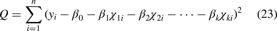
The regression coefficients are obtained by solving partial derivatives of Equation (23) set to zero.
Step 5: Data normalization. Sample data are normalized to the [0, 1] interval interval using min-max scaling, eliminating dimensional and scale effects.
Step 6: Contribution ratio analysis. The influence of each parameter is quantified as a percentage contribution by scaling regression coefficients: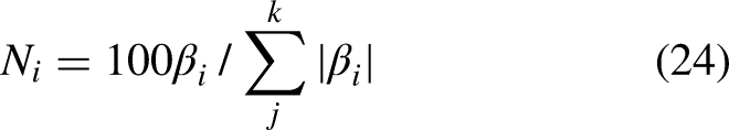
Step 7: Comprehensive sensitivity synthesis. Absolute values of sensitivity results for four key dynamic response metrics (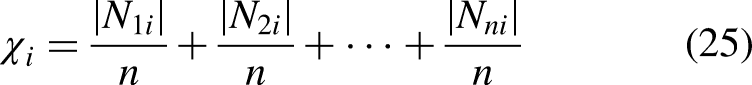
Step 8: Dynamic response variance analysis. Analysis of variance (ANOVA) is conducted to evaluate statistical significance. Total variance comprises model-explained variance and residual error. The coefficient of determination (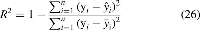
The sensitivity analysis results for each parameter's influence on
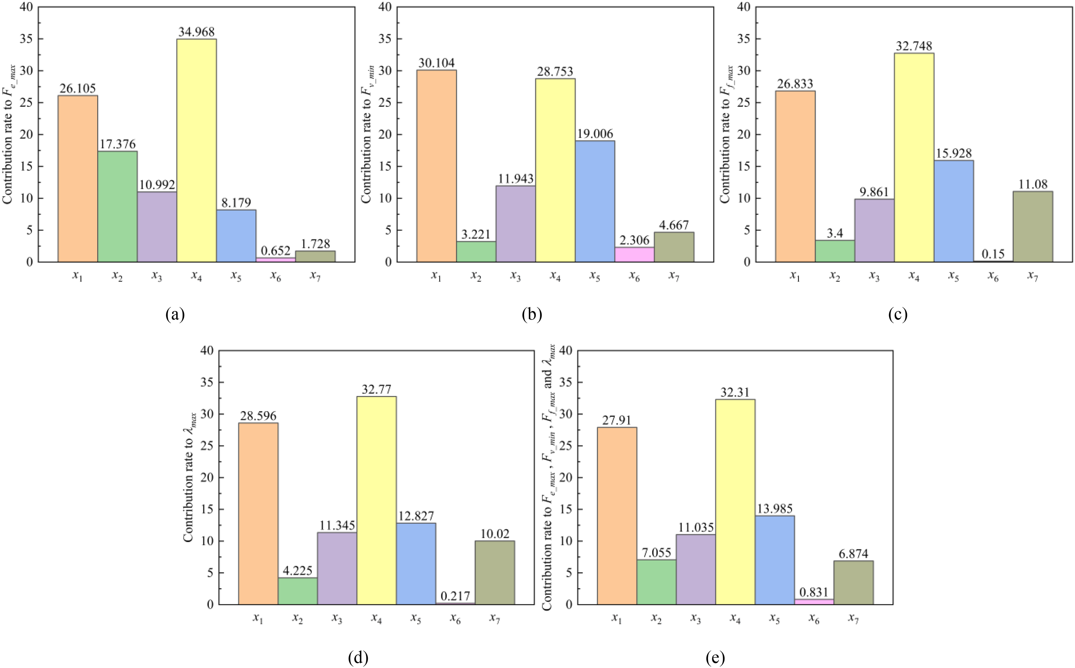
Sensitivity analysis results of the C-EMD response under intensive impact load.
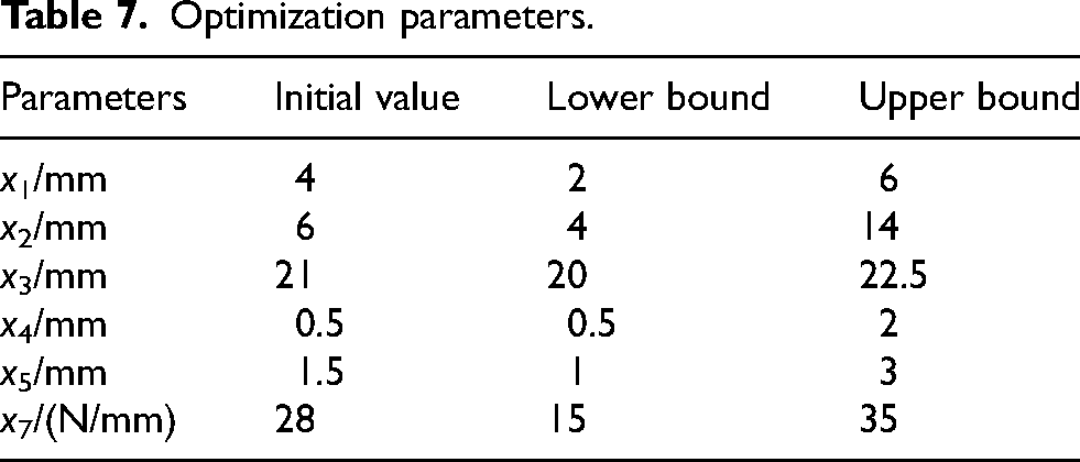
Optimization parameters.
Surrogate model construction
During the optimization of the resultant resistance in the C-EMD, the high computational cost of repeatedly invoking the coupled simulation model—owing to its nonlinearity and complexity—poses significant challenges. Direct optimization using the original model would substantially increase computational complexity, making it impractical to achieve optimal results within acceptable resource constraints. To address this, surrogate models with higher computational efficiency are widely adopted as effective substitutes for complex coupled simulations. This study evaluated multiple surrogate models, including third- and fourth-order response surface models (RSMs), radial basis function (RBF) and elliptic basis function (EBF) neural networks, Chebyshev orthogonal polynomial models, and Kriging models. Using a design of experiments approach, 150 experimental samples were generated, randomized, and normalized, with 120 samples allocated to the training set and 30 to the testing set.
The root mean square error (RMSE) was selected as the metric to evaluate the predictive performance of the surrogate models. An RMSE closer to 0 indicates smaller deviations between predicted and actual values, reflecting higher model accuracy. The RMSE is calculated as: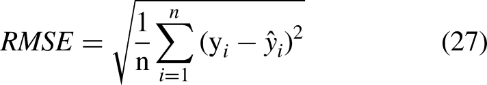
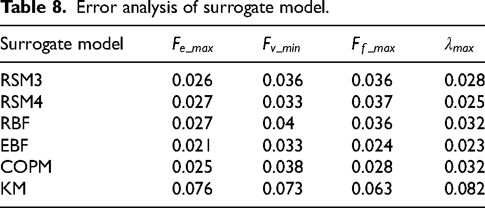
As shown in Table 8, the RMSE values for the six models demonstrate that the elliptic basis function (EBF) neural network achieves the highest accuracy and optimal performance. Consequently, the EBF model was selected for subsequent multi-objective optimization.
Error analysis of surrogate model.
The elliptic basis function (EBF) neural network is a three-layer feedforward architecture comprising input, hidden, and output layers. The hidden layer performs nonlinear transformations using the Mahalanobis distance between test points and sample centroids as inputs, expressed as:

The mapping from the hidden layer to the output layer is linear, with response values calculated via weighted summation:
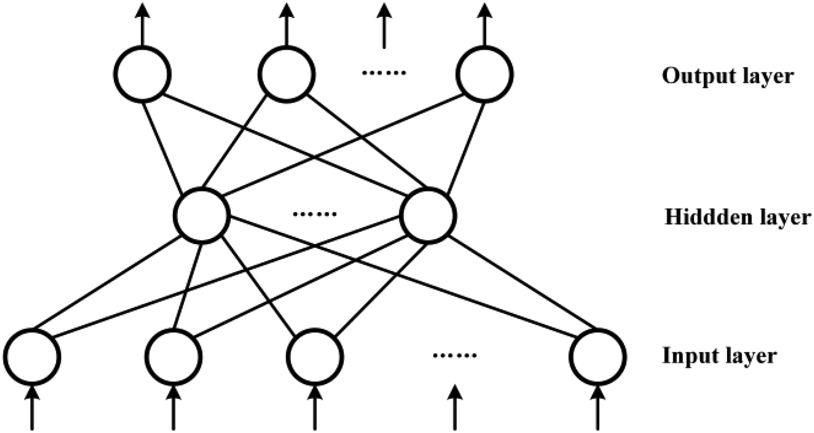
Topology diagram of the EBF model.
Optimization parameters (Table 7) include electromagnetic variables (e.g., axial iron pole length) and mechanical properties (e.g., spring stiffness). The objectives are to minimize the initial peak (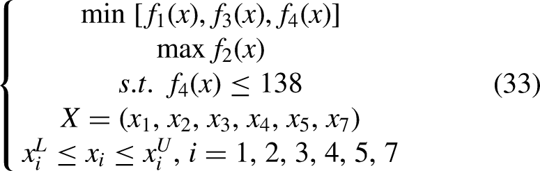
To address high-dimensional search challenges, a hybrid algorithm combining the Multi-Island Genetic Algorithm (MIGA) and Nonlinear Programming by Quadratic Lagrangian (NLPQL) was implemented. MIGA partitions populations into subpopulations (“islands”) for parallel evolution, 29 while NLPQL refines solutions locally using sequential quadratic programming. The optimization workflow is summarized in Fig. 19.
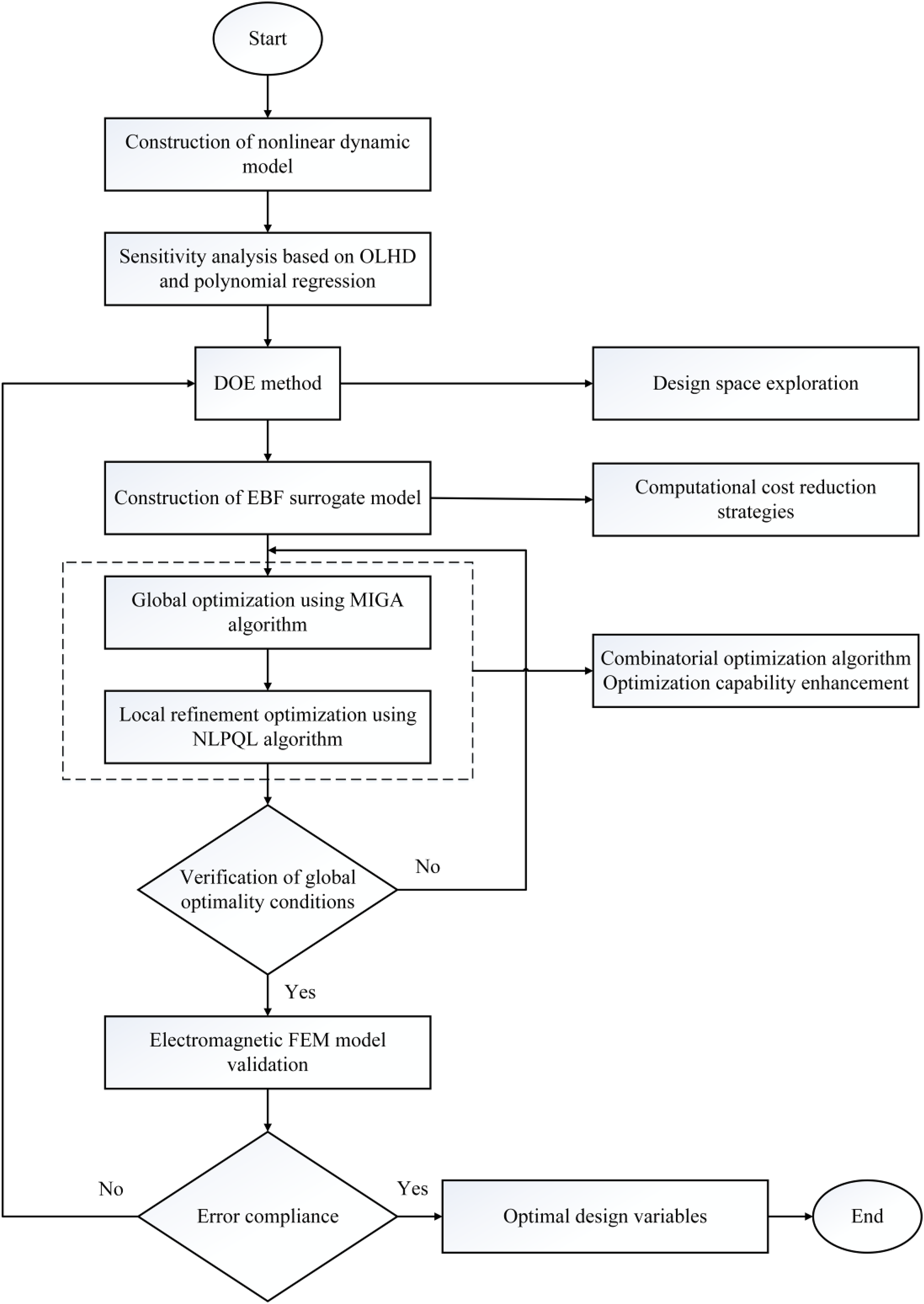
Optimization flowchart for RRF.
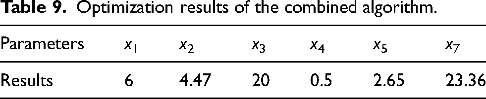
Based on Pareto multi-objective theory, an optimal parameter set (Table 9) was selected from the Pareto front, balancing engineering constraints and objective weights. Post-optimization dynamics (Fig. 20) demonstrate reduced saddle-shaped characteristics and eliminated peak protrusions, confirming enhanced damping stability. Key metrics (Table 10) show decreased initial/secondary peaks (
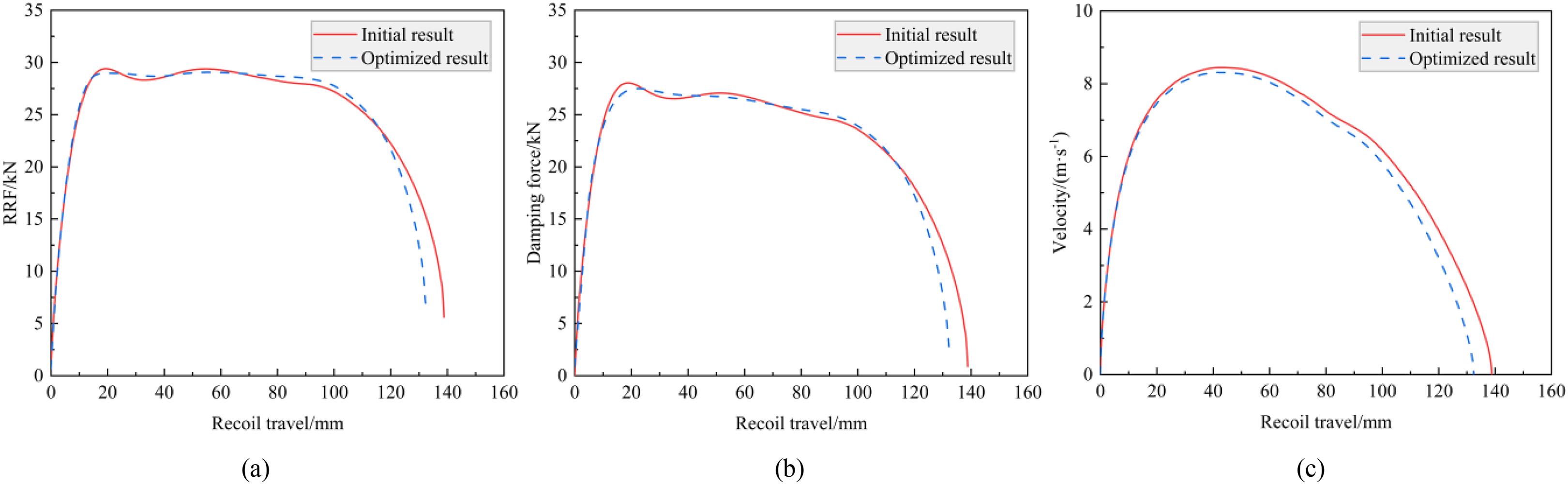
Comparison of curves before and after optimization.
Optimization results of the combined algorithm.
Target values before and after optimization.
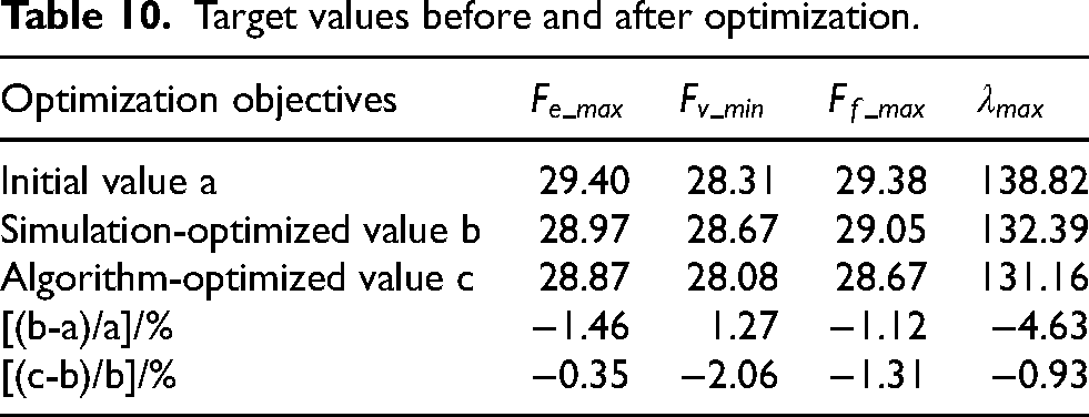
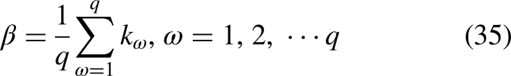
To quantify curve smoothness, fill ratio (
Under ideal conditions, the resultant resistance should maintain a constant value. Consequently, a plateau filling ratio (
Based on the C-EMD structure, this study developed a nonlinear dynamic model and validated its accuracy through experiments and finite element simulations. The influence of load on damping performance was analyzed using three sets of impact experiments with different peak values, and the effects of magnetic flux density and structural parameters on damping performance were investigated. Key parameters were screened via sensitivity analysis. Subsequently, a multi-objective optimization was achieved by employing a surrogate model and a combinatorial optimization algorithm, which effectively controlled the dynamic response. The specific conclusions are as follows:
The principle and configuration of the C-EMD were introduced. Its nonlinear dynamic and electromagnetic FEM were established. An experimental platform was built to measure the mover's motion characteristics under different impact loads, obtaining data on displacement, velocity, and acceleration, thereby validating the accuracy of the FEM. The finite element analysis indicated that as the impact load increases, the relative speed between the inner tube and the original magnetic field accelerates, generating stronger eddy currents and a more pronounced demagnetization effect, thereby influencing the damping performance. The influence patterns of structural parameters on damping performance were analyzed. Sensitivity analysis of the damper's structural parameters was conducted using OLHD and polynomial regression methods. The results showed that liner thickness and air gap thickness have the most significant impact on performance, contributing 27.91% and 32.21%, while the influence of outer tube thickness is minimal, at only 0.83%. By comparing the accuracy of six surrogate models, the EBF neural network was selected to construct the dynamic response model. After optimization using the MIGA combined with the NLPQL algorithm, the RRF curve characteristics improved significantly: the flatness decreased to 1.42, the fill ratio increased to 89.86%, the braking stability was enhanced, and the maximum displacement was reduced by 4.63%.
This study established an impact experimental platform for the C-EMD under intensive impact loads. The combinatorial optimization algorithm was successfully applied to control its dynamic response effectively, optimizing the braking performance. This work provides a new technical pathway for further enhancing the performance of EMD and holds significant value for promoting their technological development and engineering applications.
Footnotes
Funding
The authors disclosed receipt of the following financial support for the research, authorship, and/or publication of this article: The work was supported by the Postgraduate Research & Practice Innovation Program of Jiangsu Province under Grant KYCX24_0716.
Declaration of conflicting interests
The authors declared no potential conflicts of interest with respect to the research, authorship, and/or publication of this article.