






Abstract
This study focused on the damage of permanent magnets(NdFeB) in the electromagnetic buffer under the intensive impact load. According to the constitutive characteristics of the permanent magnets, a constitutive model suitable for NdFeB called damage-modified ZWT was determined. Furthermore, the specific parameters in the constitutive model were determined by fitting the constitutive curve. Then the incremental expression was established for the constitutive model and the model was embedded into ABAQUS via the VUMAT subroutine interface. A dynamic model of the electromagnetic buffer was established and calculated. After that the evolution and distribution law of damage in permanent magnets under the intensive impact load were clarified by analyzing the finite element results. Finally the damage of the device is reduced by optimizing the geometric parameters. The results show that the permanent magnets near the inner ring are damaged more from the radial distribution of the damage and the permanent magnets on both sides are damaged more from the lateral distribution of the damage, which provides a reference for the design of electromagnetic buffers.
Keywords
Introduction
According to electromagnetic induction theorem, eddy currents are caused due to relative motion of the source magnetic field and the conductor. Eddy currents create magnetic fields and cause a repulsive force proportional to the relative velocity of the field and conductor. The electromagnetic buffer is a new type of brake device designed based on the above principle. Electromagnetic buffers are divided into electromagnetic brakes, permanent magnet brakes and hybrid brakes depending on the excitation source. Compared with electromagnetic brakes and hybrid brakes, permanent magnet brakes do not require external excitation power supply and excitation winding. They save electricity and copper usage, reduce the size of the device, and simplify the structure of the device. On the other hand, their reliability is higher because there is no danger of brake failure during power failure [1].
According to the braking principle of the permanent magnet electromagnetic buffer, it can be seen that permanent magnets are the excitation source of the whole device. Whether permanent magnets can provide sufficient source magnetic field and whether their mechanical properties and magnetic properties are stable are the key factors of the performance of the brake. Due to the high remanence, high coercivity and high magnetic energy product of sintered NdFeB, the use of sintered NdFeB in electromagnetic buffers has great advantages in terms of magnetic field. Many scholars at home and abroad have done a lot of research on the magnetic field distribution and braking force characteristics of electromagnetic buffers during operation [2–5]. However, with the continuous expansion of the application field of electromagnetic buffers, their working conditions are more and more severe, and their load strength is also increasing. Structurally, due to the complex crystal structure and the low slip system, NdFeB have poor plasticity. At the same time, Li et al. [6] pointed out that NdFeB are mostly sintered magnets and there are a certain amount of pores and defects in it, which also reduce the material strength and toughness of NdFeB. Therefore, the permanent magnet electromagnetic buffer can not only consider the magnetic field during the working process under the intensive impact load. The mechanical properties of NdFeB are also critical to the operation of the brake. Wang et al. [7] obtained the engineering stress-strain curves at different strain rates by uniaxial compression and dynamic fracture tests of sintered NdFeB. They considered that The tensile hoop stress, axial stress and shear stress in the expanding specimen cause the surface cracks. Shan Tao et al. [8] studied the effect of different annealing temperatures on the compression curve of the magnet. It is found that the higher the annealing temperature, the lower the compressive stress value. At present, the mechanical properties of NdFeB are mostly studied itself. However there is almost no study of the mechanical properties when it is applied in a specific device.
In this study, the dynamic mechanical properties of NdFeB were described by one-dimensional elastic brittle damage- modified constitutive model and damage-modified Zhu–Wang–Tang (ZWT) constitutive model. By comparison, it was found that the damage-modified ZWT constitutive model can better describe the stress-strain characteristics of NdFeB at different strain rates. The incremental form of damage-modified ZWT constitutive model was established and the material subroutine was written. After that the subroutine was embedded into the dynamic model of electromagnetic buffer to analyze the damage of NdFeB caused by the intensive impact load. Finally the damage of the device is reduced by optimizing the geometric parameters.
Damage constitutive model
There are a certain number of pores and fine cracks inside the sintered body. These defects undergo the connection of pores and the growth of micro-cracks to form a dynamic damage process under the intensive impact load [9]. Damage constitutive model is to introduce damage factor D into the existing constitutive model [10]. Material damage behavior is the process of material damage accumulation. When the damage reaches the limit, the material is damaged. The process from no damage to gradual damage can be measured by damage factor D. The Seeger and Jhonson-Cook models, as constitutive models that often describe metal materials, are not accurate enough in describing the mechanical properties of NdFeB. In this paper, a one-dimensional elastic-brittle damage-modified constitutive model and a damage-modified ZWT constitutive model are introduced to fit dynamic mechanical properties of NdFeB and compare.
Through a lot of experimental research on different materials (including metal materials, polymer materials and concrete materials, etc.), it has been consistently shown that: The high-speed deformation process of materials is often accompanied by different forms of internal micro-damage evolution processes, which ultimately lead to the destruction of materials. The observed internal defects / damages of the material are mainly represented by microcracks, microvoids and shear bands on the meso-scale, while dislocations and luan crystals appear on the micro-scale. The various forms of dynamic damage are not actually a simple transient response, but a dynamic process that includes different forms of damage evolution.
Regarding the damage in the form of microcracks, it can be seen from many experimental data that the evolution of damage depends on both strain and strain rate, which is similar to the thermal activation mechanism of dislocation motion. The literature [11] proposes a damage evolution model based on the thermal activation mechanism.
As we all know, the strain rate-dependent constitutive relationship of metal materials is commonly explained by the thermally-activated motion of line defect dislocations inside materials on the microscopic mechanism.
Based on the concept of Kachnov’s continuity factor, Rabotonv first defined the damage variable as
On this basis, Lemartire proposed in 1971 that the strain response of a damaged element under stress σ is the same as the strain response of a non-destructive element under a defined effective stress
The relationship between effective stress
The constitutive equation of the damaged material in the one-dimensional problem based on the strain equivalence hypothesis is:
The evolution process of micro-damage is regarded as a stress-promoted thermal activation process, which is similar to the thermal activation motion equation of metal materials.
Assuming that there is a threshold ϵ
th
for damage evolution, we can get
In more general cases, there may be a non-linear relationship with D and ϵ, generalize the above formula to a more general form
NdFeB and Al2O3 ceramics are both elastic-brittle materials. The internal structure of sintered materials is difficult to produce dislocation and slip. At room temperature, almost no plastic deformation occurs and fracture failure occurs within the elastic range. According to the one-dimensional elastic-brittle damage-modified constitutive model of Al2O3 ceramics established by Zhang et al. [12], the one-dimensional elastic-brittle damage-modified constitutive model of NdFeB can be constructed as
The dynamic and static mechanical properties of the sinter are quite different. The damage-modified ZWT constitutive model can describe the mechanical behavior under different strain rates well. It has been widely applied in materials such as concrete, ceramics and plexiglass [13–15].
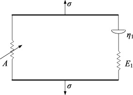
Physical model of ZWT constitutive.
The damage-modified ZWT constitutive model consists of a nonlinear spring and a linear Maxwell element connected in parallel. Its physical model is shown in Fig. 1 and the equation of the constitutive model is expressed as below
According to the NdFeB dynamic compression experimental curve obtained by Lei et al. [16], the two constitutive models are fitted with the stress-strain curve in the literature by the least squares principle. The fitting comparison are shown in Fig. 2.
When the strain rate are 1456 s−1, 1774 s−1, 2764 s−1, the correlation index R 2 of the curve fitting with the one-dimensional elastic-brittle damage-modified constitutive model are 0.832, 0.845 and 0.744, respectively. The correlation index R 2 of the curve fitting with the damage-modified ZWT constitutive model are 0.984, 0.986 and 0.983, respectively. On the whole, the damage-modified ZWT constitutive model has a higher degree of fitting with literature values and it can better reflect the stress-strain relationship of NdFeB under different strain rates.
After fitting, the NdFeB damage-modified ZWT constitutive equation is expressed as
The equation should first be rewritten into an incremental form before embedded into the finite element program. The process of establishing the incremental form will be described in detail below.
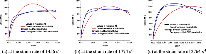
The fitting and comparison of two constitutive models at different strain rates.
Incremental form of damage-modified ZWT constitutive model [17]
Considering the finite deformation, the second Kirchhoff stress and Green strain are adopted to expand the ZWT model to the three-dimensional form.
In the case of small deformations, the Green strain is approximately equal to the Cauchy strain.
Therefore the above formula (19) can be rewritten as
The process of establishing the incremental form of the second term in equation (21) is as follows.
Converting the integral term in the equation (25), we obtain equation (26).
In this way, the incremental form of the ZWT constitutive model is obtained.
Kirchhoff stress is also called pseudo-stress and Cauchy stress is real stress. The relationship between Kirchhoff stress and Cauchy stress is
The expression of the damage factor is
Since the damage is unrecoverable, it’s necessary to determine whether the strain is increasing.
The incremental expression for the damage factor is
The expression of the stress tensor containing damage is
The incremental form of the stress tensor containing damage is
The Kirchhoff stress is converted to Cauchy stress according to equation (16):
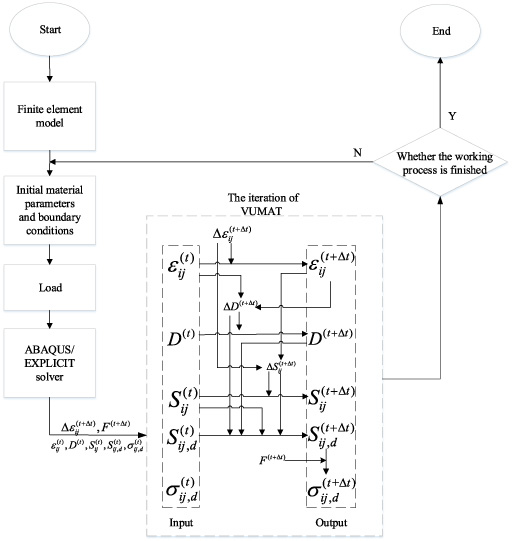
ABAQUS calculation process of embedded material subroutine.
Although ABAQUS has a powerful library of material constitutive models, it can not cover all situations. When the user needs to define the constitutive model of the material autonomously, the material subroutine interface VUMAT of ABAQUS is needed. The running process of the subroutine is shown in Fig. 3. At the beginning of the incremental step, the main program passes the initial values to the corresponding variables via the subroutine interface. The subroutine VUMAT processes and updates these variables and then returns the processed variables to the main program at the end of the subroutine [18,19]. For the damage-modified ZWT constitutive model mentioned in this paper, the calculation flow of ABAQUS calling subroutine is as follows, where the specific process of updating the value of each variable is given by the above formula.
The damage-modified ZWT constitutive equation was implemented in Fortran language to set up its incremental form. As shown in Fig. 4, the numerical simulation model of a single NdFeB was established and the subroutine was embedded into the ABAQUS solver for finite element analysis. It can be seen from Fig. 5 that the fitted values are in good agreement with the simulated values at each strain rate. This verifies the correctness of the written subroutine. Therefore, the following part will establish the dynamic model of the electromagnetic buffer and associate it with the VUMAT subroutine of NdFeB. And the dynamic response of electromagnetic buffer under the intensive impact load and the damage distribution of permanent magnets will be analyzed.
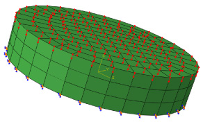
Uniaxial compression model of a single permanent magnet.
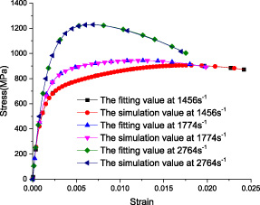
Comparison of fitted values of damage-modified ZWT constitutive model and simulation values under different strain rates.
As stated in the introduction, electromagnetic buffers utilize the relative motion between the conductor and the source magnetic field. The two relative moving parts of brakes are usually referred to as the primary and secondary. As shown in Fig. 6, the electromagnetic buffer includes primary: magnetic shoes, permanent magnets, the moving rod, the guide ring and the end nut; secondary: the conductor cylinder and the end cover. The material properties of each part are shown in Table 1.
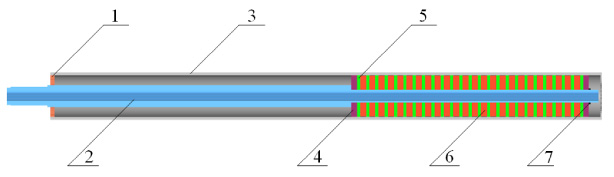
Structure diagram of the electromagnetic buffer. 1 - End cover; 2 - The moving rod; 3 - Conductor cylinder; 4 - Guide ring; 5 - Magnetic shoes; 6 - Permanent magnets; 7 - End nut.
Material properties sheet for each part
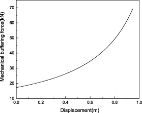
The dynamic model of the electromagnetic buffer is shown in Fig. 7. When the electromagnetic buffer is in operation, the intensive impact load is applied to the left end of the brake, so that the primary accelerate to the left. When the magnetic shoes and the permanent magnets move relative to the conductor cylinder, it generates the damping force opposite to the movement direction. At the same time, the displacement-related resistance is applied to the right side of the moving rod to simulate the mechanical buffering force during the actual working process. The curves of the intensive impact load and the mechanical buffering force are shown in Fig. 8 and Fig. 9, respectively. The contact collision relations are defined where the moving rod, the guide ring, magnetic shoes, permanent magnets and the end nut are in contact.
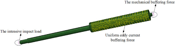
Dynamic model of the electromagnetic buffer.
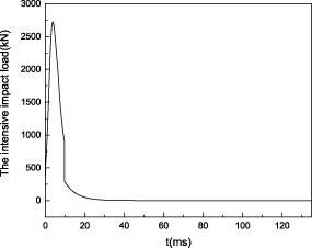
Curve of the intensive impact load.
Curve of the mechanical buffering force.
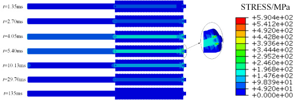
The stress distribution of the electromagnetic buffer is determined by the external load. In the initial stage, the intensive impact load rises rapidly in a short time and reaches its peak near 5 ms. During this time, the intensive impact load is transmitted to the entire brake through the moving rod, and the overall stress of the brake is also rising. At 5.40 ms, the peak stress appears at the collision between the right end nut and the right guide ring, and the peak stress is 590.4 MPa. After that, the intensive impact load decreases rapidly, which results in the stress decrease of the electromagnetic buffer.
Stress distribution in the cross-section of the electromagnetic buffer at different times.
Damage factor distribution of the rightmost permanent magnet at different times.
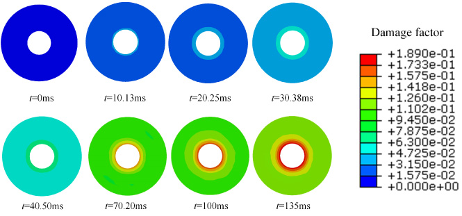
The rightmost permanent magnet is taken to analyze the damage over time. The calculation results in Fig. 11 show that the damage factor D is increasing throughout the whole operation of the electromagnetic buffer. At the same time, it can be clearly seen that the value of the damage factor gradually decreases from the inner ring to the outer ring. This is due to the fact that the intensive impact load first acts on the moving rod. During the process of transferring the load to the permanent magnets, the moving rod and the permanent magnets generate a large friction force, resulting in a large strain of the permanent magnet inner ring. As the radial distance increases, the other positions are not in direct contact with the moving rod. So the strain at other positions is small, which results in the gradual decrease of the damage factor from the inside to the outside.
The position of three points (A,B,C) on the permanent magnet.
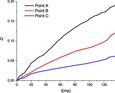
The curve of damage factor with time.
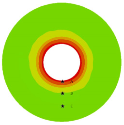
In order to better analyze the distribution law of the damage factor along the radial direction of the permanent magnets, three points ABC are taken out as shown in Fig.12. Through the analysis according to Fig. 13, it can be found that the two points of BC do not directly contact with the moving rod and the damage factor decreases with the increase of the distance from the inner ring. The damage factors of BC at the end of the operation are 0.119 and 0.061, respectively. However, due to the constant contact and collision between the inner ring and the moving rod during the operation, the damage factor at point A is relatively large and the damage factor value at the end of the operation is 0.189.
As stated above, we define the damage value according to the load capacity under the same strain. As the formula (35) shown below, there is a difference between the stress for the same strain when the material is damaged and not damaged. This is because the damage of internal microstructure leads to the degradation of the macroscopic elastic modulus E of the material. The damage is characterized by the degradation of elastic modulus and the relation between the equivalent elastic modulus after damage and the elastic modulus of undamaged material is
As can be seen in Fig. 14, with the increase of the intensive impact load, the extreme value of strain almost appeared at the same time as the stress peak. Later, due to the combined effect of the intensive impact load, eddy current buffering force and friction, the strain value fluctuates continuously and gradually decreases to 0 in the fluctuation with the advance of time. According to the definition of damage in the ZWT constitutive model, damage occurs when the absolute value of strain increases in two adjacent analysis steps as shown in the formula (36). And because the damage value D is irreversible, although the overall strain is decreasing, the damage factor D is still increasing due to the existence of fluctuations.
Figure 15 shows the cross-section damage factor distribution of permanent magnets at different times. When the intensive impact load increases rapidly, the moving rod generates a large acceleration along the load direction and the right side of the permanent magnets have a large contact collision with the end nut. Therefore, the damage factor of the right-end permanent magnets increases rapidly within 5.4 ms and the maximum value reaches 0.018. In the next time, the permanent magnets are subjected to eddy current damping force, frictional contact force with the moving rod and collision force with the guide ring. The results show that the combined force of the left-end magnetic steel is larger and the damage is greater.
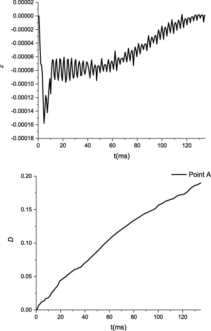
Axial strain history curve and damage value at point A.
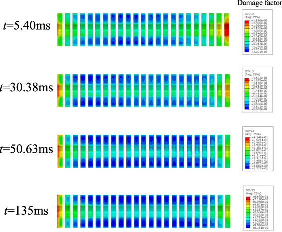
Damage factor distribution in the cross-section of permanent magnets at different times.
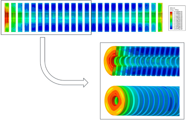
Distribution and local enlargement of damage factor below 0.2.
In order to show the damage degree of permanent magnets more clearly, according to the definition above, the upper limit of the damage factor is set to 0.2 and the damage distribution map at 135 ms is analyzed. As shown in Fig. 16, it can be seen that the leftmost permanent magnet has a uniform circumferential destruction. At the same time, according to Fig. 16 and the radial damage distribution of the rightmost permanent magnet in Fig. 12, it can be known that the peak damage factor value of the rightmost permanent magnet is 0.189, and no destruction occurs. Therefore, the damage of the left permanent magnet is larger than that of the right permanent magnet at 135 ms. Additionally, as can be seen from the cloud diagram in Fig. 16, the damage cloud colors of the permanent magnets on the left and right sides are basically green, yellow, and red, but the middle part is blue and cyan. According to the numerical comparison on the right, it can be seen that the damage value of the permanent magnets on both sides is greater than the damage value of the permanent magnets in the middle part.
In fact, for different materials and different constitutive model, methods which used in the risk assessment are not the same. The theory and simulation should be compared with the experiment so that a more accurate evaluation method can be obtained. As mentioned in the introduction of this article, most of the previous articles for sintering of NdFeB focused on its magnetic properties. We lack evaluation standards similar to other metal and non-metallic materials. Since the permanent magnets provide the source magnetic field in the buffer, the permanent magnets are equivalent to the power system of the whole device. The damage of the permanent magnet’s mechanical properties will also have a great impact on its magnetic properties. In this paper, for the sake of conservative safety assessment, 0.2 is taken as the critical damage value of permanent magnet and the damage of degree (DOD) is defined according to the critical damage value:
According to this definition method, it can be calculated that the DOD of the permanent magnets in this paper is 0.208%. It can be seen that the DOD is small. However, the permanent magnet on the left side has a large damage, which will also have an impact on the whole. The DOD of the left-most permanent magnet is 5.0%. According to this definition of DOD, the geometric dimension is adjusted to optimize the damage degree.
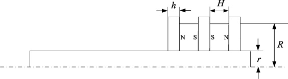
Schematic diagram of parameter position.
As presented in Fig. 17, there are three parameters of permanent magnets, namely its inner diameter r, outer diameter R and height H. At the same time, the magnetic shoe acts as a magnetically permeable material in the magnetic field and as a contact piece between permanent magnets in the structural field. Its height h will also affect the magnitude of the eddy current buffering force and the damage degree of the permanent magnets. Therefore, the four parameters of h, r, R, and H are used as design variables and the objective function is to minimize the damage. At the same time, it is considered that both the buffer can weaken the impact load and the structure of the buffer should be as compact as possible. After preliminary trial calculation, the value range and initial value of the four parameters are determined in Table 2.
The initial value and value range of four parameters
Latin hypercube design is an experimental design method based on space filling. It can make the limited samples fill the whole design space as much as possible and weaken the requirement of sample boundary. Latin hypercube design has the characteristics of super nonlinear response fitting ability, which can better reflect the physical essence of the research object. The optimal Latin hypercube design greatly improves the uniformity of the Latin hypercube design by adding a criterion and it is especially suitable for multi-factor, multi-layer experiments and the situations where the system model is completely unknown.
In view of the strong nonlinear characteristics in the working process of the buffer, this paper selects the optimal Latin hypercube experimental design to obtain sample points. A total of 20 training samples are generated and the samples are shown in Table 3.
In this paper, the method of constructing the proxy model is used to simplify the complicated calculation process. We optimize the proxy model to improve computing efficiency. Common methods for constructing proxy models include response surface method, radial basis function method, and neural network method. The neural network [20] has strong non-linear mapping capabilities. A 3-layer BP neural network can fit any complex non-linear function. So this paper uses neural network to build a proxy model. BP neural network modeling process is shown in Fig. 18.
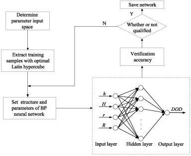
BP neural network modeling process.
Genetic algorithm (GA) [21] is a method to search the optimal solution by simulating the biological evolution process in nature. According to the determined fitness function, we use selection, crossover, and mutation as the three main genetic operators to operate on individuals in the population. Populations evolve through continuous exchange of chromosomal information between individuals. Eventually, individuals with good fitness values are retained and individuals with poor fitness values are continuously eliminated during the evolution process. After constant evolution, individuals in the population gradually approach the optimal solution. Moreover, since genetic algorithm does not care about the mathematical relationship between design variables and objective functions, nor does it need information such as the gradient of objective functions to determine the search direction, it is very suitable for parameter optimization.
Tables of traning samples
Parameters’ initial value and optimized value
In this paper, the neural network model is optimized by genetic algorithm, and the optimized parameters are shown in Table 4.
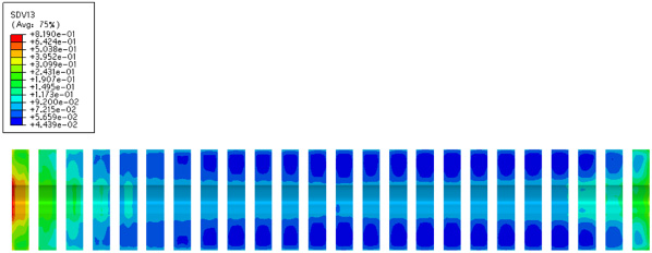
The optimized result cloud map.
According to the optimization results in Fig. 19, it can be seen that the peak value of the damage factor is 0.819, which is 5.5% lower than the initial 0.867. At the same time, according to the statistical results of the grid, the optimized DOD is 0.105%, which is 49.5% lower than the previous. The peak value decreases less, but the overall grid damage degree decreases more obviously. The safety of the device has been greatly improved. It also illustrates the effectiveness of the optimization method.
In this paper, the strain-rate dependent dynamic constitutive equation of N38 is established. The incremental form is established and embedded into the dynamic simulation model through the VUMAT subroutine. The damage evolution and distribution of the permanent magnets in the specific device are obtained and the specific conclusions are as follows
(1) Compared with the one-dimensional elastic-brittle damage-modified constitutive model, the damage-modified ZWT constitutive model has a higher degree of fitting with the stress-strain curve of sintered NdFeB. Therefore, the damage-modified ZWT constitutive model can better describe the dynamic constitutive characteristics of sintered NdFeB at different strain rates.
(2) It can be seen from the uniaxial compression simulation of a single permanent magnet model that the simulated values are in good agreement with the fitted values. This shows that the established incremental form is relatively correct.
(3) From the radial damage distribution, the damage of NdFeB decreases gradually from the inner ring to the outer ring. From the lateral damage distribution, the NdFeB on both sides are damaged more and the NdFeB in the middle part are less damaged. Therefore, the contact parts at both ends between the permanent magnets and the moving rod are damaged greatly, which should be paid attention to in design and use.
Footnotes
Acknowledgements
The work was primarily supported by the National Natural Science Foundation of China (grant number 301070603).