
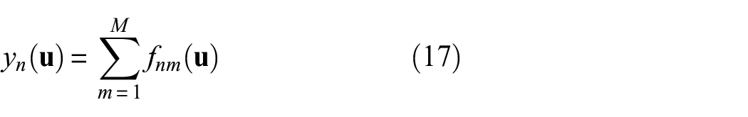
Abstract
This article presents a multipath Lamb wave imaging method that leverages the extra reflections present in the recorded ultrasonic waveforms for structural prognosis. Under the ray acoustic approximation, an edge behaves like a mirror, which changes the propagation path of a wave and provides more views of the damage than can be obtained from direct scattering. To accommodate for these extra reflections, the scattering path of each wave in the residual signal is simplified as a direct scattering path from an actual or virtual transmitter (created by edge mirroring) to the damage, and then back to an actual or virtual receiver (created by edge mirroring). On this basis, the Gaussian distribution function is introduced to quantify the probabilities at each spatial node in relation to all possible damage loci. Through fusing the images obtained from all individual wave packets, the structure could be inspected with far fewer transducers compared to conventional elliptical imaging. Experimental results from carbon fiber-reinforced polymer laminates and aluminum plate are provided to illustrate the effectiveness of the imaging method, where damage is correctly detected and accurately localized even with a single transmitter–receiver pair.
Introduction
Lamb waves have been acknowledged as a very promising technique for structural health monitoring (SHM), due to their well-established theories and ability to detect different types of damages within relatively large inspection areas.1–3 Moreover, recent advancements in transducer technologies used for Lamb wave sensing and excitation (e.g. piezoelectric transducers, PZTs) give the possibility to develop a permanently installed SHM system for structural prognosis.4,5
Generally, the application prospect of a SHM system for continuous health monitoring may be determined by the reliability, cost, and the interference to the performance of host structure. Therefore, tremendous research has been focused on optimal placement of sensors/actuators, so as to monitor Lamb wave propagation with the minimum number of transducers. 6 Wilcox 7 used an omni-directional guided wave array consisting of a circular pattern of sensor elements for large plate inspection. Malinowski and colleagues8,9 investigated the performance of both triangular and concentrated configurations of PZTs for simulated damage (i.e. magnets) detection on an aluminum plate. Flynn and Todd10,11 proposed a Bayesian approach for optimal sensor and/or actuator placement for SHM applications. Thiene et al. 12 presented an optimal sensor placement algorithm for maximum area coverage for damage localization in composite structures. In these studies, the single-scattering approximation is commonly used, which treats the target (i.e. damage) to be imaged as a singular feature in a smooth known background and abandons the large number of echoes and reverberations in the structure.
In reality, however, waves can bounce multiple times between the damage and other singular features (e.g. edges, stiffeners and lap joints) before returning to the detector. 13 Leveraging the echoes and reverberations present in the recorded Lamb wave signals, it is possible to improve damage imaging performance with far fewer transducers compared to conventional imaging approaches.14,15 Muller et al. 16 used the waves reflected from the free edge of the plate to determine the initial conditions of the imaging system, such as wave speed and sensor position. Rodriguez et al. 17 presented a one-channel defect imaging method based on the application of topological optimization methods to exploit multiple reflections in the reverberating medium. Hall and Michaels 18 incorporated a large number of echoes and reverberations into an imaging algorithm so that the damage could be reliably detected by a small number of transducers. However, the baseline collection relies on laser vibrometer scanning, which may limit the number of times the baseline is collected during the service life of the structure and increase the overall cost of the monitoring system. Ebrahimkhanlou et al.19,20 presented a model-based Lamb waves imaging algorithm where multiple ultrasonic echoes caused by reflections from the plate’s boundaries are leveraged to enhance imaging performance. However, the assumption that there is no overlapping between two echoes may face challenge under dispersive circumstances.
In this paper, an imaging method which incorporates multipath scattered signals is presented, where the multipath scattering between the damage and edge is equivalent to mirroring a virtual transducer on the other side of the boundary. That enhances the imaging process in the way that the image is obtained from a sensor array consisting of both actual and virtual transducers, rather than a single actual transmitter–receiver pair. The rest of the paper is organized as follows. Section “Background” gives the theoretical analysis of Lamb wave scattering. Subsequently, the multipath Lamb wave imaging method is proposed in section “Multipath Lamb wave imaging.” In sections “Experimental validation in CFRP laminates” and “Experimental validation in aluminum plates,” the performance of the proposed method is investigated in the carbon fiber-reinforced polymer (CFRP) laminates and an aluminum plate, respectively. Finally, the conclusions are drawn in section “Conclusions.”
Background
Suppose a Lamb wave mode is excited at a particular location on a plate,

with
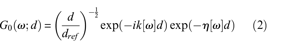
Here,
If there is a damage present at location
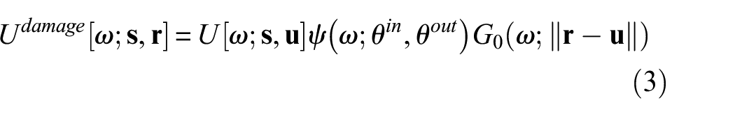
where ψ(ω;θ
in
,θ
out
) indicates the scattering pattern at the damage, θ
in
=∠(
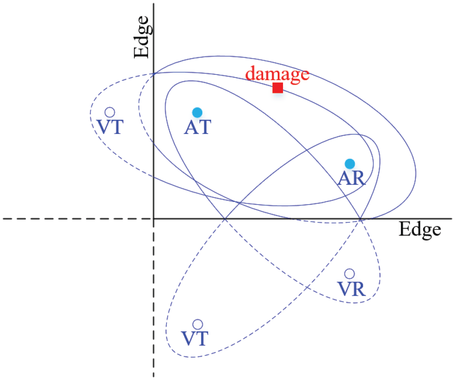
When the structure also contains known singular features, the extra reflections can capture more information about the damage as they give rise to waves that probe the damage from different directions. In this study, the late arrival reflections from boundaries are incorporated into damage detection. For illustration, Figure 1 gives the scattering paths associated with the damage
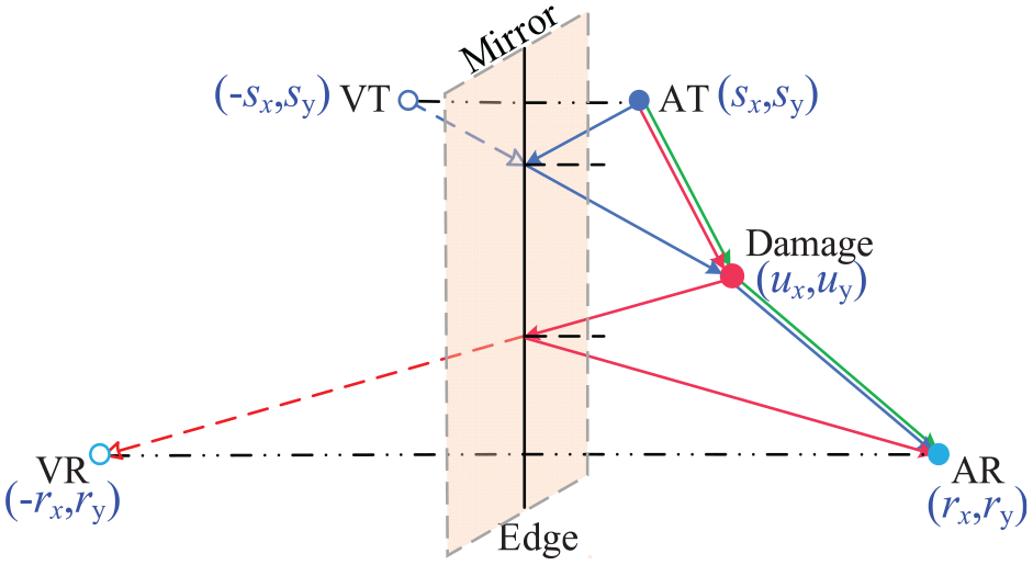
Edges behave like mirrors that add virtual transmitter and receiver at the symmetrical locations of the actual ones with respect to the boundary.
From the viewpoint of ray tracing, an edge behaves like a mirror which creates a virtual transmitter at
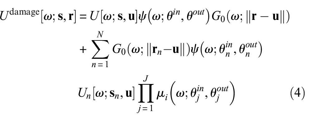
here, N is total number of virtual sensing paths in the sensor network.
In SHM, sensors are permanently attached to the structure, thus allows for highly accurate repeated measurements. This repeatability enables the recording of baseline measurements to track changes in the time-traces that can potentially be related to structural damage.
24
Especially, the residual signal that subtract this baseline signal Ubaseline[ω;
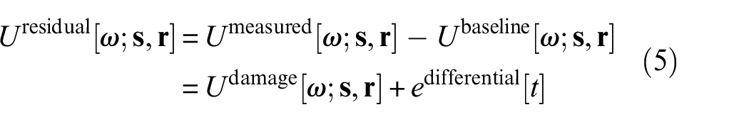
It is noted that the variations of environmental and operational conditions (EOC) may affect the variability in the measurements, resulting in imperfect subtraction of the baseline signal and arising residual signals which could be mistaken for damages. That is a major limitation of the baseline method. In recent years, tremendous research has been done to quantify the EOC effects and overcome them.25–28 Various adaptive algorithms have been developed, providing robust practical solutions for compensating the EOC effects on the structure.24,25,29–31 Benefiting from that, the EOC effects are not further discussed thereafter, and any mismatch resulting from them is only considered as noise in equation (5), that is, edifferential[t].
Multipath Lamb wave imaging
As mentioned, a single transmitter–receiver pair operating under multipath scattering circumstance is equivalent to a sensor array consisting of both actual sensor elements and virtual ones operating under single-scattering approximation (see Figure 1). However, that sensor array differs from the conventional ones on two aspects. First, the composition of sensor array is uncertain, as it is possible that a few actual/virtual transmitter-receiver pairs “catch” the “directly scattered” waves from damage while the others “miss” them. Second, it is nearly impossible to match the wave packets in the residual signal with the direct scattering paths of the actual/virtual transmitter-receiver pairs in the sensor array unless the location of the damage site is known. Therefore, the conventional elliptical methods may not be available under multipath scattering circumstance.
In this section, to exploit multipath scattering for damage detection and localization, an imaging method is established as follows.
If there is damage located at

here,
The solutions to equation (6) configure an ellipse-like locus of root.
32
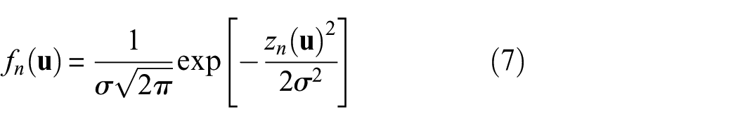
To quantify the probabilities at all the spatial nodes in relation to all the loci, the Gaussian distribution function fn(
with

here, σ is the standard deviation, which controls the width of the Gaussian bell and further controls the resolution of damage imaging, taking 8 in this paper. fn(
It can be observed from equation (5) that the residual signal consists of a series of wave packets associated with multipath scattering. Though the time of arrival and propagation distance of each wave packet could be obtained. There are two questions need to be answered before damage imaging (i.e. equation (7)), that is, whether the nth transducer pair “captures” a “directly scattered” wave from damage, and which wave packet in the residual signal matches that direct scattering path. In practical applications, the location of damage site is always unknown, thus neither question can be answered.
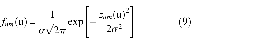
To address this issue, it is assumed that a wave packet in the residual signal may come from any possible transmitter-receiver pair in the sensor array. Accordingly, equations (7) and (8) change to
with

here, the subscript n still represents the nth transmitter–receiver pair, while the subscript m denotes the mth wave packet in the residual signal.
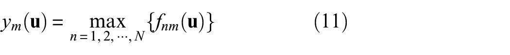
For a particular wave packet, each transmitter–receiver pair could produce an image through equation (9). If these images are fused together by taking the maximum value at each pixel
Possible loci of damage calculated from the sensor array related to a particular wave packet in the residual signal.
where N is the number of all possible transducer pairs in the sensor array.
Finally, the images related to all wave packets fm(
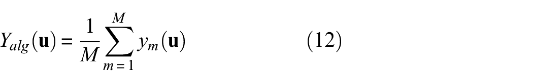
where M is the number of wave packets in the residual signal.
Experimental validation in CFRP laminates
Procedure
The experimental setup consists of an Agilent 33,220A function/arbitrary waveform, a NF HSA4012 voltage amplifier, and an Agilent DSOX3014A oscilloscope. The specimen is a quasi-isotropic CFRP laminates with dimensions of 690 mm × 690 mm × 2 mm (Figure 3). It is made of 16 plies of T300 carbon fibers embedded in the 7901 epoxy resin with a layup of [+ 45o/-45o/0o/90o]2s. A coordinate system is employed, where the left vertical edge is ℝ1 = {(x, 0)|x∈ℝ, x > 0} while the lower horizontal edge is ℝ1 = {(0, y)|y∈ℝ, y > 0}, so that the area to be imaged belongs to the set ℝ2 = {(x, y)|x∈ℝ, y∈ℝ, x, y > 0}.
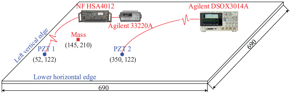
Scheme diagram of experimental setup.
The transmitter and receiver are two PZTs (P-51 with dimensions of Φ8 mm × 0.5 mm) centered at (52, 122) mm and (350, 122) mm, respectively. A typical chirp with its frequency sweeps from 10 to 110 kHz over a 1 ms rectangular window is taken as the excitation signal, to achieve a high signal-to-noise ratio in the CFRP laminates. 35 The Lamb wave response is recorded from the pristine plate as the baseline signal with a sampling frequency of 2 MHz and a data length of 10,000 points. The amplitude responses of A0 mode and S0 mode are obtained from the baseline signal via time-frequency analysis, 36 and displayed in Figure 4. It can be seen that in the excitation frequency range, A0 mode is quite strong while S0 mode is much weak. That may be attributed to the tuning between PZT and Lamb waves in CFRP laminates. 37 Therefore, only A0 mode is considered thereafter.
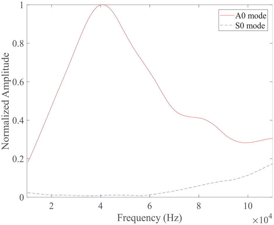
The excitation provides a virtually pure A0 mode propagating in the structure as A0 mode is much stronger than S0 mode.
Similar to Guo and Cawley 38 and Rose et al., 39 an added mass with the dimensions of 15 mm × 15 mm × 4 mm is bonded to the specimen as a simulated damage. After that, Lamb wave testing is repeated, and the response is recorded from that damaged plate. The discrepancy between the captured signal and the baseline comes from the simulated damage, and the residual signal isolates its effects.
Pulse compression is then applied to the residual signal, which is equivalent to applying the auto-correlation to the actual excitation waveform 40
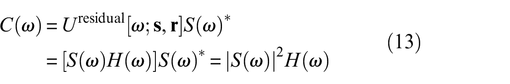
Here, S(ω) is the Fourier transform of the chirp excitation, the superscript * represents the complex conjugate. H(ω) is the transform function representing the effects of damage, which could be obtained as H(ω) = Uresidual[ω;
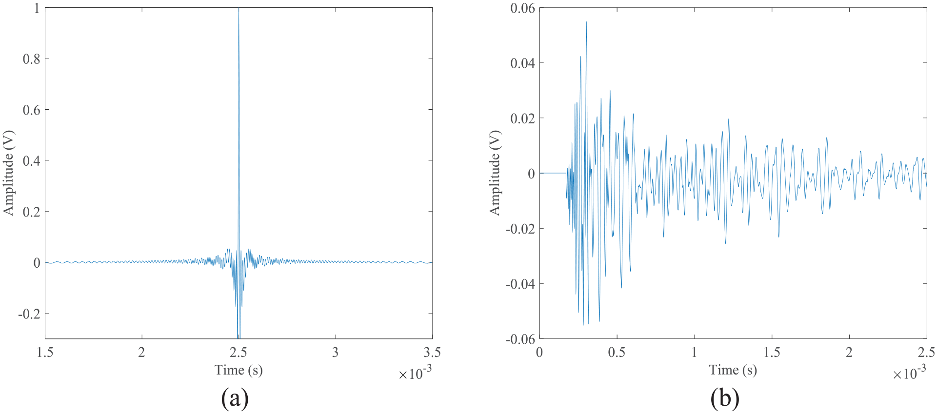
Auto-correlation of the (a) typical chirp excitation and (b) the pulse compression signal calculated from the residual signal.
Dispersion compensation41,42 and sparse decomposition43,44 are two commonly used methods to address this issue. Specifically, the typical sparse decomposition problem is the recovery of a sparse vector

where
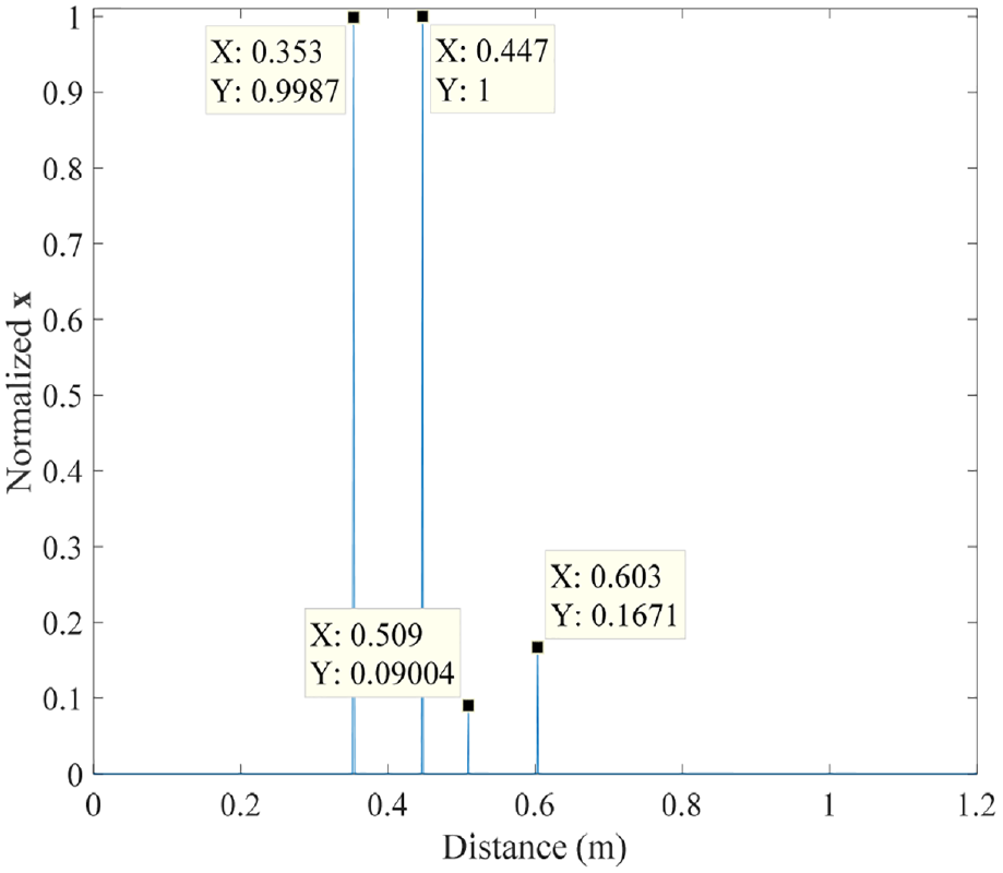
The sparse decomposition result of the residual signal.
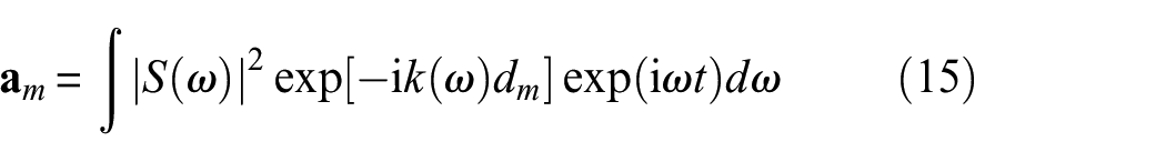
To ensure enough range and accuracy, the propagation distance dm varies from 0.2 to 1 m with an increment of 0.001 m, and thus the dictionary
Equation (14) is often either underdetermined or overdetermined as N≠M. Thus, l1-optimization method is introduced to solve this problem
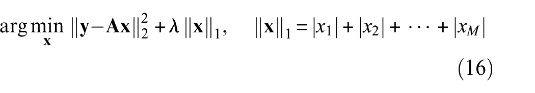
where λ is a user-specified regularization parameter, which balances the accuracy (2-norm term) and sparsity (1-norm term). In this paper, it is set as λmax/10, where λmax = max|
As discussed in section “Background,” exploiting multipath scattering is equivalent to adding virtual transmitters and receivers into the sensor array, and further, the multiple scattering paths could be simplified as the direct scattering paths from the virtual/actual transmitters to damage, and back to the actual/virtual receivers. In this experiment, the transmitter sits adjacent to both the left vertical edge and the lower horizontal edge, mirroring virtual transmitters at VT1 (-52,122) mm and VT2 (52, -122) mm, respectively. The receiver stands close to the lower horizontal edge, adding a virtual receiver centered at VR1 (350,-122) mm. From the viewpoint of ray tracing, there should be many more virtual transmitters or receivers arising from multipath scattering, for example, VT’ (-52,-122) mm, VR’(-350,122) mm, and VR” (-350,-122) mm in Figure 7. Considering the scattering pattern and attenuation factor, it is of large possibility that the four wave packets in the residual signal come from the several shortest and low-order scattering paths. Therefore, those extra virtual transmitters and receivers are not considered, and the sensor array consists of three transmitters (including an actual one and two virtual ones, i.e. AT, VT1, and VT2) and two receivers (including an actual one and a virtual one, i.e. AR and VR1). It provides a total of six sensing paths, that is, only one is actual and the rests are virtual.
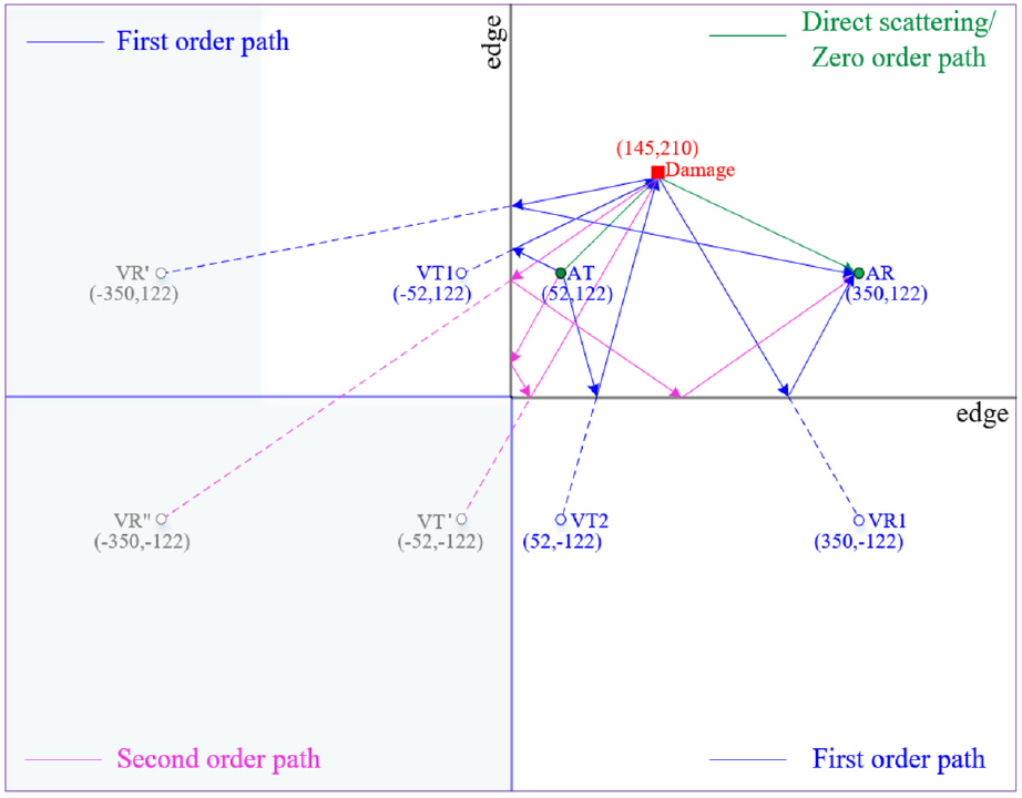
Scheme diagram of the transmitter–receiver pairs in the sensor array.
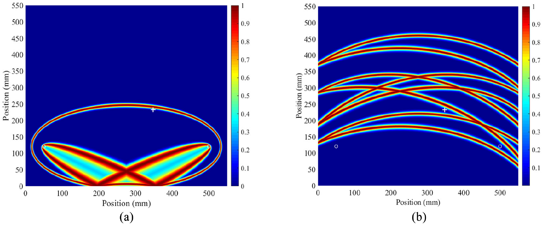
Substituting the coordinates of the transmitters and receivers, and the propagation distance of an individual wave packet into equation (9) and in sequence (11), all possible loci of damage related to that wave packet could be obtained. The resulting images corresponding to the four wave packets are displayed in Figure 8(a) to (d), respectively. Each image is normalized by its maximum value, and the center of the actual damage is marked by “+.” It can be seen that in each image, a large probability value for the presence of damage arises at the location of the damage site. It means that each wave packet is “captured” by one of the transducer pairs in the sensor array, as the “directly scattered” wave from damage. Besides, in Figure 8(c) and (d), six elliptical loci could be identified, corresponding to the six transducer pairs in the sensor array. However, in Figure 8(a), there is only one elliptical locus. The reason lies that the propagation distance of the first wave packet (i.e. 353 mm) is even smaller than the distances between transmitter and receiver of other transducer pairs expect for the shortest one.
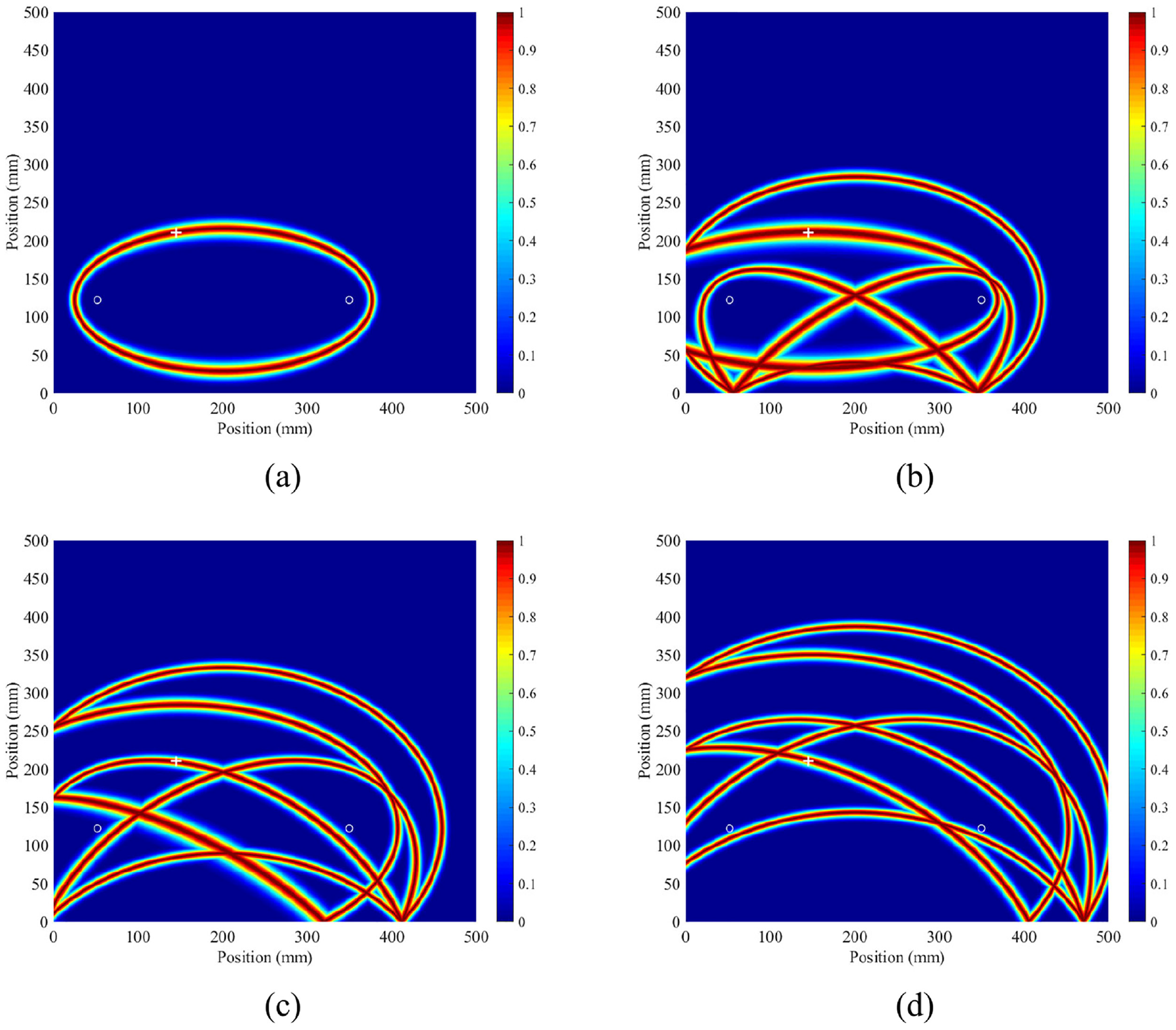
The resulting images corresponding to the four wave packets: (a) the first wave packet with a propagation distance of 353 mm, (b) the second one with a propagation distance of 447 mm, (c) the third one with a propagation distance of 509 mm and (d) the fourth one with a propagation distance of 603 mm.
Subsequently, the arithmetic mean (i.e. equation (12)) is applied to combine these four images together. Figure 9 shows the fused image. It can be seen that the area with high probability values for the presence of damage coincides with the actual one quite well. Especially, the grid with the highest probability value is identified at (147, 210) mm and marked by “o.” It matches the center of the actual damage (marked by “+”) quite well. In summary, Figure 9 demonstrates the effectiveness and efficiency of the multipath Lamb wave imaging method for damage detection.
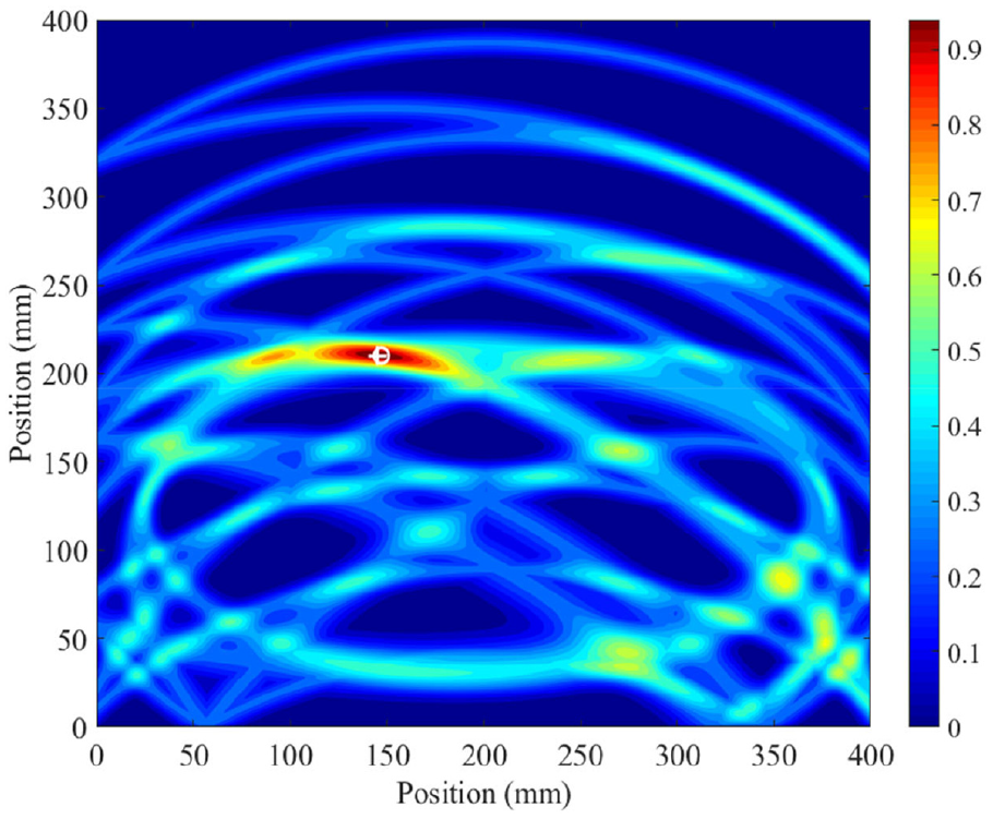
Image constructed using the proposed multipath Lamb wave imaging method.
Discussions
In conventional elliptical imaging methods, damage localization is often achieved through fusing images related to all transmitter-receiver pairs in the sensor array. In this experiment, only one residual signal is obtained, which consists of several wave packets (including the directly scattered wave and extra echoes). It is nearly impossible to trace the scattering path of an individual wave packet, as the location of the damage site is unknown. In other words, each individual wave packet possibly comes from the “direct” scattering path of any transmitter-receiver pair in the sensor array. Therefore, all possible loci of damage should be considered first. Figure 10(a) to (f) give the probabilities of the presence of damage at all the spatial nodes in relation to the loci computed from each individual transmitter–receiver pair, that is
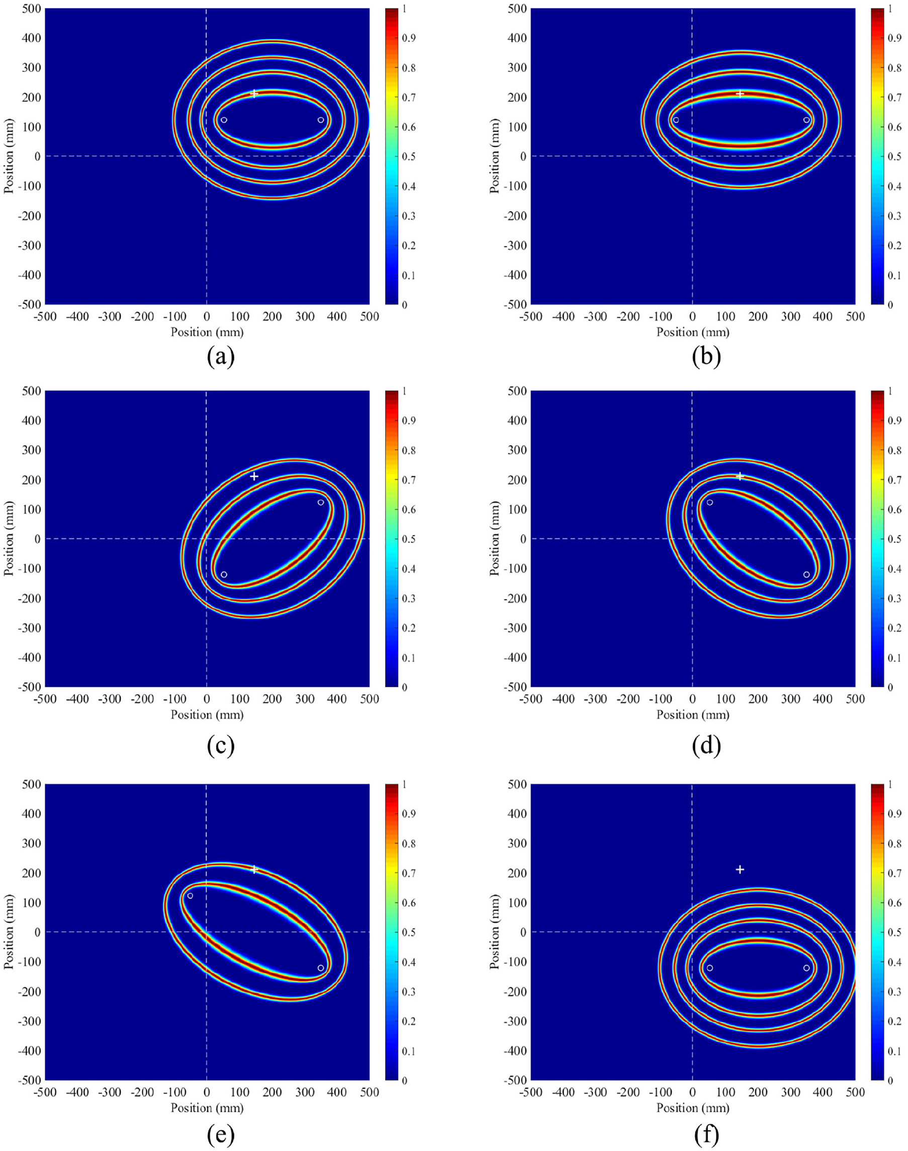
The damage imaging results obtained from each possible transmitter–receiver pair: (a) transducer pair 1, (b) transducer pair 2, (c) transducer pair 3, (d) transducer pair 4, (e) transducer pair 5 and (f) transducer pair 6.
where fnm(
Subsequently, the arithmetical mean is adopted to fuse images related to all transmitter–receiver pairs
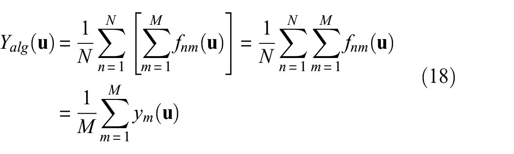
with
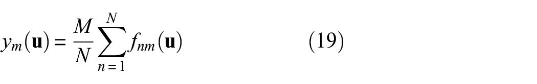
where N is the number of all possible transducer pairs in the sensor array. In essence, the only difference between equation (18) and the multipath Lamb wave imaging method is that the fusion strategy changes from the maximum (i.e. equation (11)) to the arithmetical mean (expect for the constant M), that is equation (19).
The images obtained from equation (18) are displayed in Figure 11(a), (b) and (d), as the sensor array consists of transmitter-receiver pairs 1–4, 1–5, and 1–6, respectively. The center of the actual damage is marked by “+” in each image. In Figure 11(a), it can be seen that the damage cannot be precisely detected, as the highest probability values for the presence of damage (marked by “o”) is identified at (90, 209) mm. That is far away from the actual location of the damage site. Besides, a large number of fake peaks arise, further contaminating the imaging result. The reason behind that could be explained as follows. Equation (18) is equivalent to combining images corresponding to all transducer pairs in the sensor array through arithmetical mean. In that sensor array, transducer pairs 1, 2, and 4 “capture” the “directly scattered” waves from damage (see Figure 10(a), (b) and (d)). Thus, there are three elliptical loci intersect at the damage site, producing a high imaging value there. However, since all wave packets in the residual signal are incorporated into damage imaging, there are a total of 13 elliptical loci related to the four transducer pairs in the sensor array (see Figure 10(a) to (d)). It is possible that there are three or even more loci intersect at another point, producing a large imaging values and arising a false suspect. Figure 11(b) achieves the best performance of damage imaging, where the identified damage coincides with the actual one well. However, there are still some imaging artifacts in that image. Figure 11(c) shows the result as all six images in Figure 10 are fused together for the case that the sensor array consists of six transducer pairs. It can be seen that the identified damage deviates from the actual one again. That may be attributed to the interference of transducer pair 6 (see Figure 10(f)), as it “misses” the “directly scattered” waves from damage while introduces four artificial loci into the fusing process.
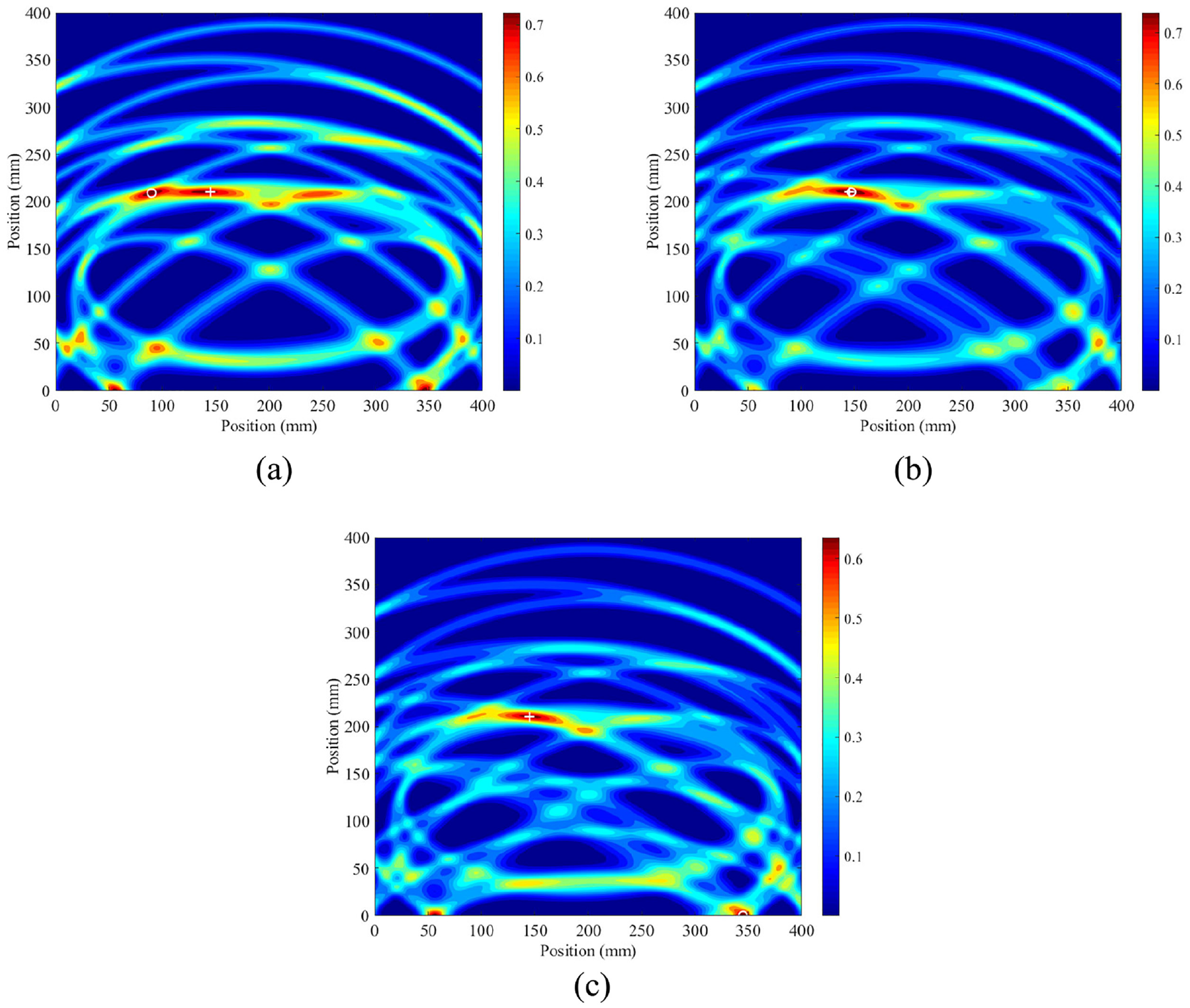
The images of simulated damage obtained from equation (17) as the sensor array consists of different transmitter-receiver pairs: (a) transducer pairs 1–4, (b) transducer pairs 1–5, and (c) transducer pairs 1–6.
For comparison, the multipath Lamb wave imaging method is also employed for damage localization. Figure 12(a) and (b) display the imaging results as the sensor array consists of transmitter–receiver pairs 1–4 and 1–5, respectively. In Figure 12(a), though the identified damage is also away from the actual one, the imaging artifacts are obviously suppressed. Furthermore, when the sensor array consists of transmitter-receiver pairs 1–5, the identified damage matches the actual one quite well, as shown in Figure 12(b). Even the transducer pair 6 which “misses” the “directly scattered” wave from the damage is brought into the sensor array, the damage imaging is still of high accuracy, that is, Figure 9. This improvement on the reliability and validity of the multipath Lamb wave imaging method comes from the fusion strategy. Specifically, the maximum value strategy (i.e. equation (11)) helps the multipath Lamb wave imaging method to alleviate the interference caused by the intersection of different loci. For further illustration, it can be seen from Figure 8 that the imaging value at the crossover point of two or more different loci is almost the same as those at other points of the loci.
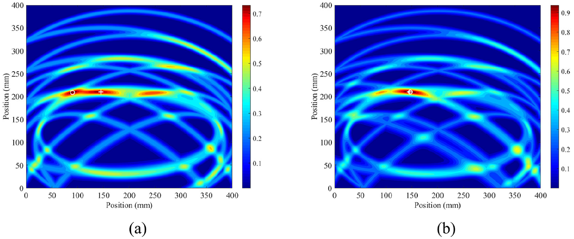
The images of simulated damage obtained from the proposed multipath Lamb wave imaging method as the sensor array consists of different transmitter-receiver pairs: (a) transducer pairs 1–4 and (b) transducer pairs 1–5.
Experimental validation in aluminum plates
In this experiment, the specimen is a 2024 T3 aluminum plate with dimensions of 1000 mm × 1000 mm × 2 mm. A coordinate system is employed, with its origin sits at the lower left corner of the specimen. Two PZTs are surface mounted on the specimen, serving as the transmitter and receiver, respectively. The transmitter AT sits adjacent to both the left vertical edge and the lower horizontal edge, while the receiver AR stands close to the lower horizontal edge. Figure 13 demonstrates the direct, first order and second order scattering paths from the transmitter to the damage, and from the damage to the receiver. As the material damping in the aluminum plates is much weaker than that in the composite materials, all transmitter-receiver pairs are possible to “capture” the “directly scattered” wave from the damage. In this section, for simplicity, virtual transmitters and receivers sitting far from the boundaries are not considered, for example, VR’ (-500,102) mm, and VR” (-500,-120) mm. Therefore, the sensor array consists of four transmitters [including an actual one and three virtual ones, that is, AT (50,120) mm, VT1 (-50,120) mm, VT2 (50,-120) mm and VT3 (-50,-120) mm] and two receivers [including an actual one and a virtual one, that is, AR (500,120) mm and VR1 (500,-120) mm]. It provides a total of eight sensing paths, including an actual one and seven virtual ones.
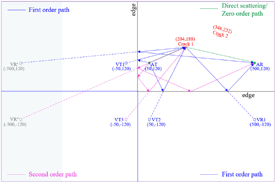
Scheme diagram of the transmitter-receiver pairs in the sensor array.
The excitation signal takes a 3-cycle toneburst signal centered at 60 kHz. It has a frequency bandwidth similar to the chirp excitation, but with a relatively simple waveform. Thus the pulse compression in equation (13) could be avoided. The Lamb wave signals are captured at three states: (1) the baseline signal is captured when the structure is in the pristine condition, (2) the present I signal is captured after the introduction of the first crack with a length of 20 mm and an angle of 0 degree, and (3) the present II signal is captured after the introduction of the second crack with a length of 20 mm and an angle of 15 degrees. A0 mode dominates in the excitation frequency range,47,48 thus it is only considered thereafter.
Identification of the first crack
Subtracting the baseline signal from the present I signal isolates the effects of the first crack, that is, Crack 1 in Figure 13. Figure 14(a) displays this residual signal. Due to the high dispersion of A0 mode, wave packets cannot be separately identified. To address this issue, the sparse decomposition technique is applied, where the dictionary A consists of 451 atoms, that is, the mth column of

The residual signal obtained as the discrepancy between (a) the present I signal and the baseline signal and (b) the sparse decomposition result.
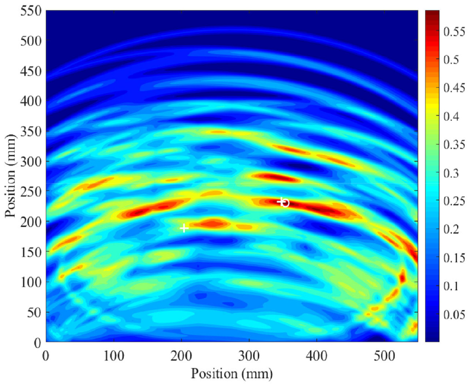
Once the propagation distance of each individual wave packet is obtained, the multipath Lamb wave imaging method is employed for damage identification. Figure 15 displays the imaging result as the sensor array consists of all the eight transmitter–receiver pairs. The central location of the actual crack is marked by “+,” while the central location of the identified damage (the grid with the highest probability value for the presence of damage) is marked by “o.” Specifically, the coordinate of the center of the identified damage is (210,191) mm, and the relative distance between it and the actual center of the crack (i.e. (204,188) mm) is 6.71 mm. It can be seen that the damage is correctly identified and accurately localized.
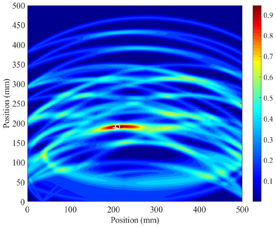
Imaging result of the first crack obtained from the proposed multipath Lamb wave imaging method.
As mentioned, the total number of transmitter-receiver pairs (i.e. 8) is larger than the number of wave packets (i.e. 5). Especially, there are three false transmitter-receiver pairs in the sensor array. Table 1 displays the matching of wave packets in the residual signal to the transmitter–receiver pairs in the sensor array. It can be seen that transducer pairs VT1-AR, VT2-AR, and VT1-VR1, “miss” the “directly scattered” wave from the damage. That may be attributed to the scattering pattern at the crack. In a word, Figure 15 demonstrates the tolerance of the multipath Lamb wave imaging method to fake transmitter-receiver pairs.
The matching of wave packets in the residual signal to the transmitter–receiver pairs in the sensor array.
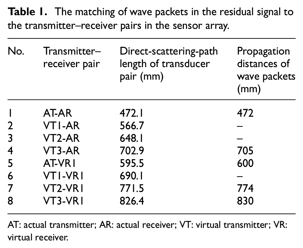
AT: actual transmitter; AR: actual receiver; VT: virtual transmitter; VR: virtual receiver.
It is noted that if the column of
Identification of the second crack
The effects of the second crack could be emphasized by subtracting the present I signal from the present II signal. Figure 16(a) shows the residual signal. Similarly, the sparse decomposition technique is applied, and the non-zero weighting coefficients provide the information of propagation distance of seven wave packets scattered from the damage, that is, 507, 516, 701, 718, 800, 816, and 848 mm, respectively (see Figure 16(b)).
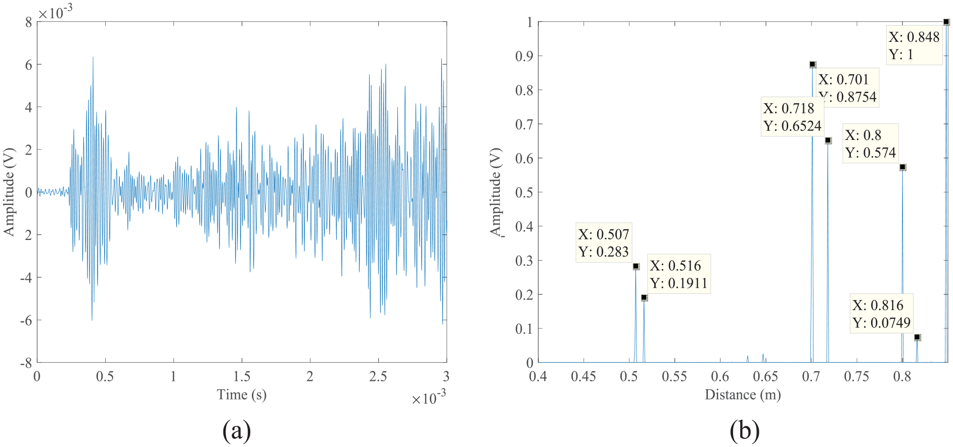
The residual signal obtained as the discrepancy between the (a) present II signal and the present I signal and (b) the sparse decomposition result.
Subsequently, the multipath Lamb wave imaging method is employed for damage detection with the same sensor array. The imaging result is shown in Figure 17. It can be seen that the damage location is also accurately identified. Specifically, the central location of the identified damage sits at (355, 232) mm, which is close to that of the actual crack, that is, (348, 232) mm. However, several low amplitude artifacts exist in the image, and the highest probability value for the presence of damage decreases compared to Figure 15. The reason may be explained from Table 2. With respect to the propagation distance, there are two wave packets in the residual signal do not match any transmitter-receiver pair in the sensor array, that is, the second one (with a propagation distance of 516 mm) and the sixth one (with a propagation distance of 816 mm). Figure 18(a) and (b) display all possible loci of damage related to these two wave packets. It can be seen that those loci isolate from the central location of the actual crack (marked by “+”). The reason lies that those two wave packets may come from the multiple scattering between the two cracks. Their propagation routes depend on the locations of damage, and cannot be equivalent to the direct scattering path of any transmitter–receiver pair which arises from edge mirroring. These false wave packets may result in a degradation in damage imaging performance.
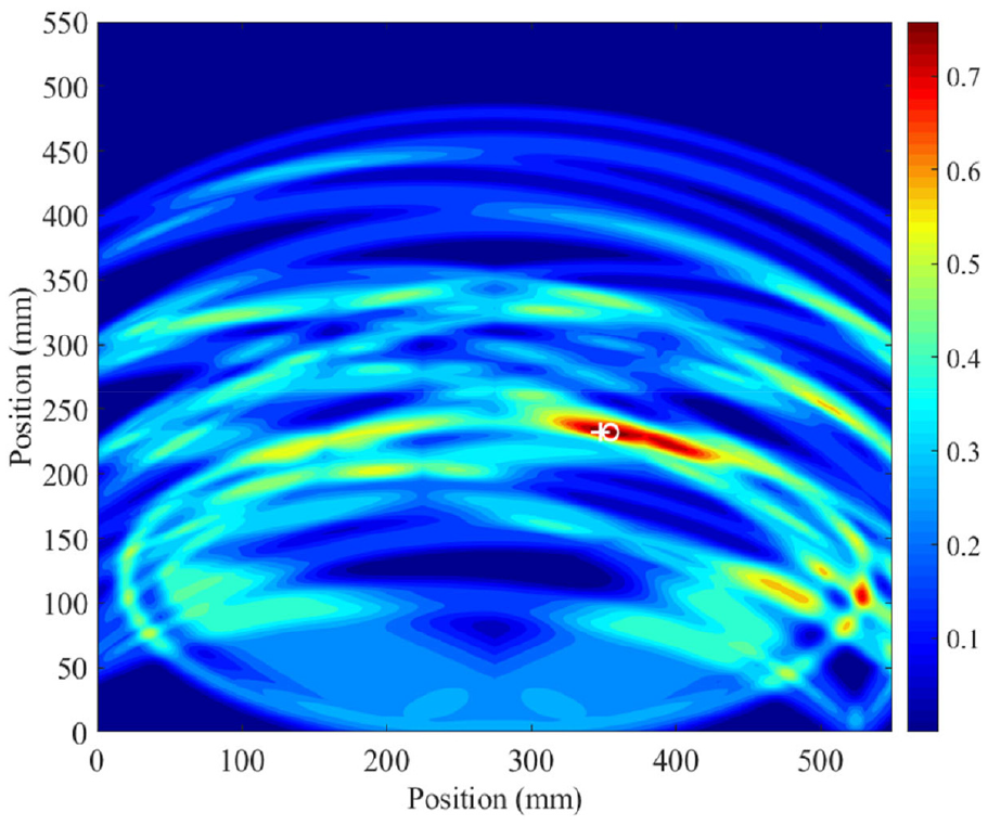
Imaging result of the second crack obtained from the proposed multipath Lamb wave imaging method.
The matching of wave packets in the residual signal to the transmitter-receiver pairs in the sensor array.
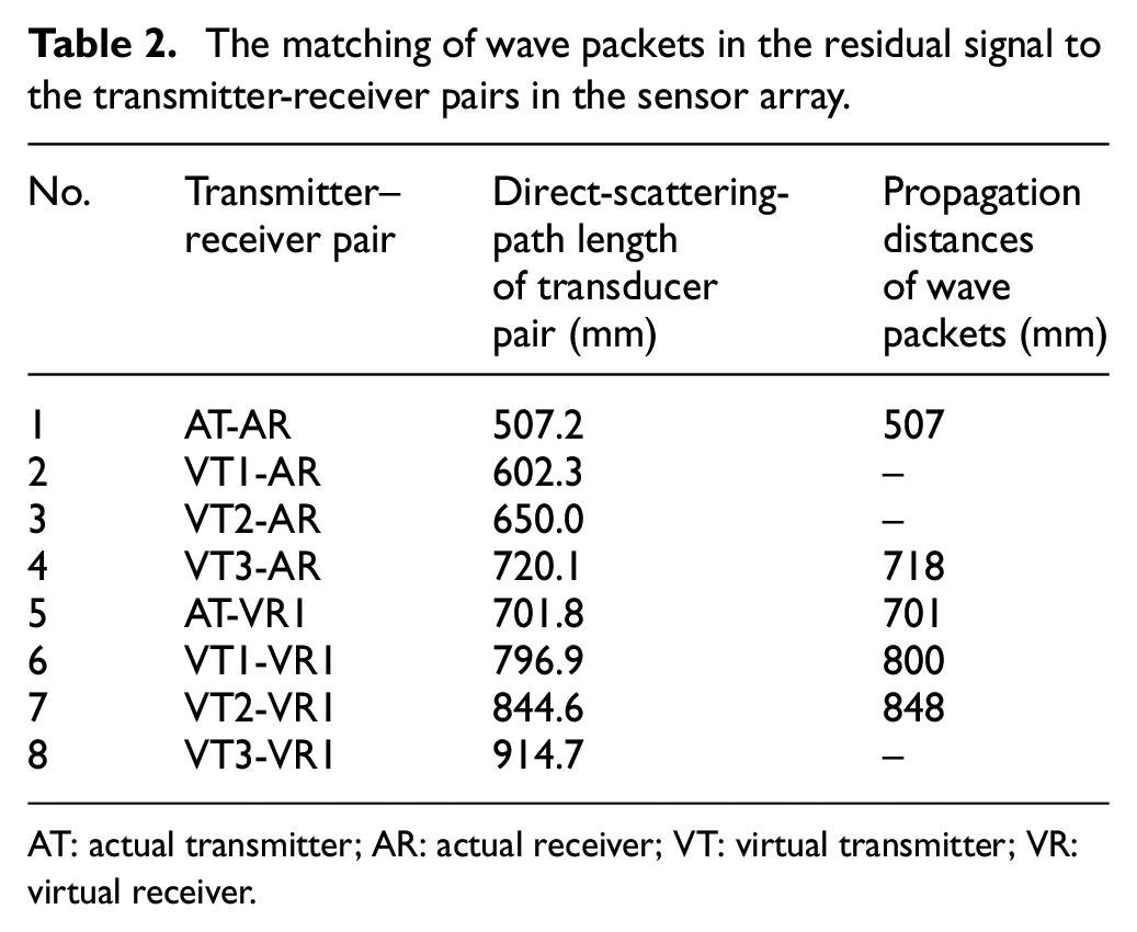
AT: actual transmitter; AR: actual receiver; VT: virtual transmitter; VR: virtual receiver.
The resulting images corresponding to two wave packets multiply scattered between the two cracks: (a) the second wave packet with a propagation distance of 516 mm and (b) the sixth one with a propagation distance of 816 mm.
Identification of two cracks
The discrepancy between the baseline signal and the present II signal contains the information of both cracks. Figure 19 shows the imaging result of the two cracks obtained from the multipath Lamb wave imaging method. The maximum of the image is correctly detected close to the actual location of the second crack. However, the highest probability value for the presence of damage further decreases. Moreover, several artifacts with high pixel value can be observed in the image, and the possibility value of some artifacts is higher than the actual location of the first crack. The reason is given as follows. In the multipath Lamb wave imaging method, all wave packets are incorporated into the damage imaging, that is, equation (12). The wave packet related to the second crack may be considered as a false wave packet to the first crack. In this case, the number of false wave packets may be even larger than that of the valid ones. As a result, a large number of intersections of different loci (i.e. artifacts) occur beyond the damage site, and the probability value at the actual location of damage decreases in image fusion, due to the arithmetical mean. Ultimately, it can be concluded that the imaging method is disadvantaged in detecting multiple damages simultaneously.
Imaging result of two cracks obtained from the proposed multipath Lamb wave imaging method.
Conclusion
This paper presents an imaging method that exploits multipath scattered signals for damage detection. These extra reflections produce waves that interrogate the structure from different directions, enlarging the element number and the aperture of sensor array. Thus, structures could be reliably inspected with the minimum number of sensors. It is of great potential in SHM, as it could reduce the equipment costs and ensure the structural integrity through reducing the sensors permanently installed on the structures.
In that method, it is assumed that a wave packet in the residual signal may come from any possible transmitter-receiver pair in the sensor array. On this basis, all possible damage loci related to that wave packet are obtained and then fused together using the maximum value strategy. Damage localization is finally achieved through fusing images related to all wave packets in the residual signal. That method does not need to differentiate the valid transmitter-receiver pairs (i.e. the ones “capture” the “directly scattered” waves from damage) from the others in the sensor array. In addition, the task of matching a wave packet to a transducer pair is also avoided. The experimental examples demonstrate its effectiveness and robustness for damage imaging.
The multipath Lamb wave imaging method is of a high tolerance to fake sensing paths. Thus, it may be appropriate to include adequate or even redundant transmitter-receiver pairs to the sensor array. If multiple damages are introduced in between different measurements, they could be detected one-at-a-time, with the multiple scattering between damages being considered as false wave packets. However, the method is not available for the case that multiple damages introduced simultaneously. That is an important and interesting aspect our future work will focus on. In addition, the extension of the idea of exploiting multipath scattered Lamb waves for damage imaging on more complex structures with arbitrary geometries, stiffened panels, welded lap joints and adhesive butt joints is another valuable research issue.
Footnotes
Acknowledgements
The authors highly appreciate the support of the National Natural Science Foundation of China, the China Postdoctoral Science Foundation, and the Fundamental Research Funds for the Central Universities.
Funding
The author(s) disclosed receipt of the following financial support for the research, authorship, and/or publication of this article: The work is supported by the National Natural Science Foundation of China (Grant No. 51875435, 51421004), the China Postdoctoral Science Foundation (Grant No. 2018M643627), and the Fundamental Research Funds for the Central Universities (Grant No. xjj2018185).