
Abstract
A short study has been conducted to assess the performance of friction stir welded Mg/steel lap joints under dynamic loads. The major mode of failure was found to be top Mg sheet fracture. Crack initiation is noted to have taken place at the Mg/steel interface. The fatigue life of the joints is found to be significantly different than the fatigue data of the Mg alloy obtained from the literature. The reasons behind such a difference have been examined in this work.
Introduction
Magnesium alloys are an excellent candidate for automotive applications due to a key combination of low density and high specific strength and, therefore, have the associated effect of weight reduction and better fuel economy. Steel, on the other hand, is currently the automaker's material of choice. This is because cold rolled mild steel (MS) offers excellent ductility, consistent properties and low overall component production costs. Therefore, use of hybrid materials for component fabrication seems promising, yet such use requires new solutions for the joining of two dissimilar metals. Magnesium and steel as two dissimilar metals pose a specific challenge. Conventional fusion welding between Mg and Fe does not work because of the huge difference in melting points, immiscibility in both solid and liquid states and absence of any congruent melting phase(s). On the other hand, a few recent studies indicate that friction stir welding (FSW), a solid state welding technique invented by Thomas et al. at TWI, UK,1 has the ability to join Mg alloys to steel. 2 2,3 Watanabe et al. 2 first studied the feasibility of joining an Mg alloy to steel in butt configuration. Chen and Nakata3 studied the effect of tool geometry on the microstructure and mechanical properties of friction stir lap welded Mg alloy and steel. In a similar work of Jana et al., 4 successful friction stir lap joint between AZ31 and Zn coated steel sheets was demonstrated with a joint efficiency of >80% in quasi-static tests.
However, it is equally important to understand the behaviour of such solid state dissimilar metal joints under dynamic loading, which is the focus of the present work.
Materials and methods
Friction stir lap welding was performed using a nominally 2·33 mm thick AZ31 magnesium alloy (O temper) of 100×305 mm in size for the top sheet. The bottom sheet was one of the two types of Zn coated steels of similar size, e.g. 1·5 mm thick high strength low alloy steel (HSLA) steel or 0·8 mm thick MS. Before welding, the lower side of the AZ31 sheet facing the steel was lightly buffed in order to expose a fresh metal surface. The sheets were clamped rigidly at a distance of ∼6 mm away from the weld centreline to ensure intimate contact between the two sheets and prevent any sheet lift-up. The Mg and steel sheet had a 38 mm lateral overlap. It is important to note that the alternative lap configuration, i.e. steel sheet on top of the Mg sheet, was not considered in the present study. This is because FSW, which is primarily based on the flow of plasticised material around the tool, would have resulted in a much higher temperature if steel sheet was placed on top of Mg sheet. There would possibly be localised melting in the bottom Mg sheet at those temperatures. Furthermore, FSW of steel is possible through the use of only a select few specific tool materials that are commercially available. This is not the case if Mg is used as the top sheet.
Welds were continuous in length at ∼250 mm. A total of four welds (i.e. two of AZ31/HSLA and two of AZ31/MS) were made in position controlled mode. A tool with convex scrolled shoulder and stepped spiral pin with a short WC insert on the pin bottom was used in the current study. The welding direction was along the AZ31 rolling direction. All the four welds were produced with identical operating parameters; tool rotation rate, travel speed and tool plunge depth were fixed at 500 rev min−1, 1·67 mm s−1 and 2·47 mm respectively. Five lap shear specimens (for fatigue testing) of ∼30 mm width and one lap shear specimen (for quasi-static testing) of ∼25 mm width were obtained from each welded sheet. An unguided lap shear test with a 1 mm min−1 crosshead speed was first carried out to evaluate the joint strength, after which the remaining lap shear specimens were then tested in a servohydraulic fatigue testing machine at a load ratio R of 0·1. The test frequency was 5 Hz. Fatigue tests were conducted in the load control mode.
Results and discussion
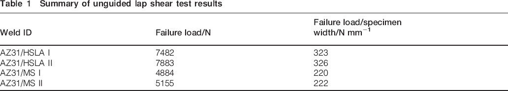
Results from the lap shear test showed the failure load for joints made with 1·5 mm steel (HSLA) to be significantly higher than those made with 0·8 mm steel (MS) due to the inherent strength difference. However, weld specimens made with 0·8 mm steel went through a considerable amount of extension before failure. Interfacial separation of the top and bottom sheets was the mode of failure for all four lap shear specimens. The lap shear test results are summarised in Table 1.
Summary of unguided lap shear test results
The S–N plot of the lap shear fatigue specimens is represented in Fig. 1a. At similar fatigue lives, the maximum applied load values are found to be higher for AZ31/1·5 mm HSLA welds than that for AZ31/0·8 mm MS welds. This is related to the higher failure load of the AZ31/1·5 mm HSLA welds. However, when the maximum applied load is normalised against the respective failure load, as shown in Fig. 1b, specimens from both material combinations are noted to have similar fatigue lives at any given applied load/failure load ratio. The major mode of failure was found to be the top Mg sheet fracture. However, three AZ31/MS weld specimens that were tested at 3 kN showed relatively longer life. Interfacial separation of the top and bottom sheet was the mode of failure for these three specimens. It can be further noted from Fig. 1b that two of the AZ31/0·8 mm MS weld specimens did not fail when the applied load/failure load ratio was <0·2. Fatigue tests for these two specimens were stopped at ∼5×10⁵ cycles.
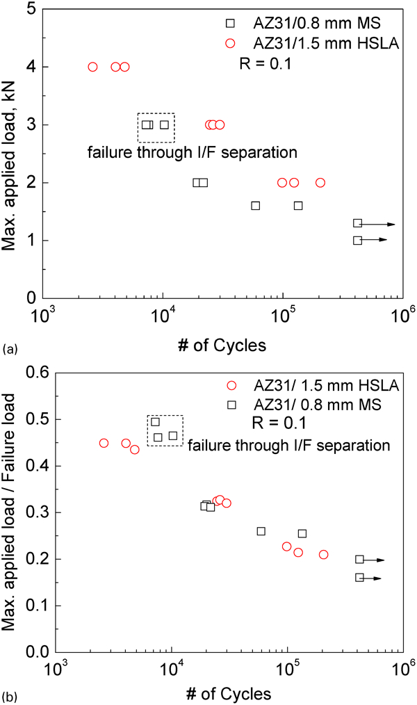
a S–N plot and b normalised S–N plot for Mg/steel friction stir lap welded specimens
A Basquin type plot (Fig. 2a), in which the stress amplitude shows a linear relationship to the number of load reversals on a log–log scale, was constructed using data points, where top Mg sheet fracture was the mode of failure. It can be noted from Fig. 2a that the load amplitude values for MS and HSLA welds have been normalised against the respective failure loads for proper comparison. The fatigue strength exponent b is given by the slope of the linear fit in Fig. 2a, which is found to be −0·185. Hasegawa et al. 5 reported b to be −0·178 based on their study on an extruded AZ31 bar. Begum et al., 6 in a separate study, reported b to be −0·15 for an extruded AZ31 alloy. Therefore, the b value determined from the current work matches well with the literature data. Furthermore, relevant S–N data of AZ31 alloy (unwelded specimens) from the literature7– 10 were compiled in an effort to compare against the present fatigue life data. For proper comparison, stress amplitude data from the literature were first converted into load amplitude and then normalised against the tensile strength of respective materials. The comparison plot is shown in Fig. 2b. It is noted that at any given Nf value, Mg fatigue fracture of the lap welded specimens took place at a much lower load amplitude/failure load ratio compared to the literature data of unwelded Mg alloy. Further examination of the literature data revealed that the yield strength (YS) and tensile strength (TS) of AZ31 specimens tested by Nan et al., 7 Uematsu et al. 8 and Ishihara et al. 9 were on the order of 200 and 270 MPa respectively. However, Tokaji et al., 10 for their AZ31 specimens, reported YS and TS of 110 and 224 MPa respectively. Interestingly, it can be noted in Fig. 2b that the data by Tokaji et al. 10 cannot be grouped together with the rest of the literature results. Notable variation in the strength value may be the reason behind such an observed difference.
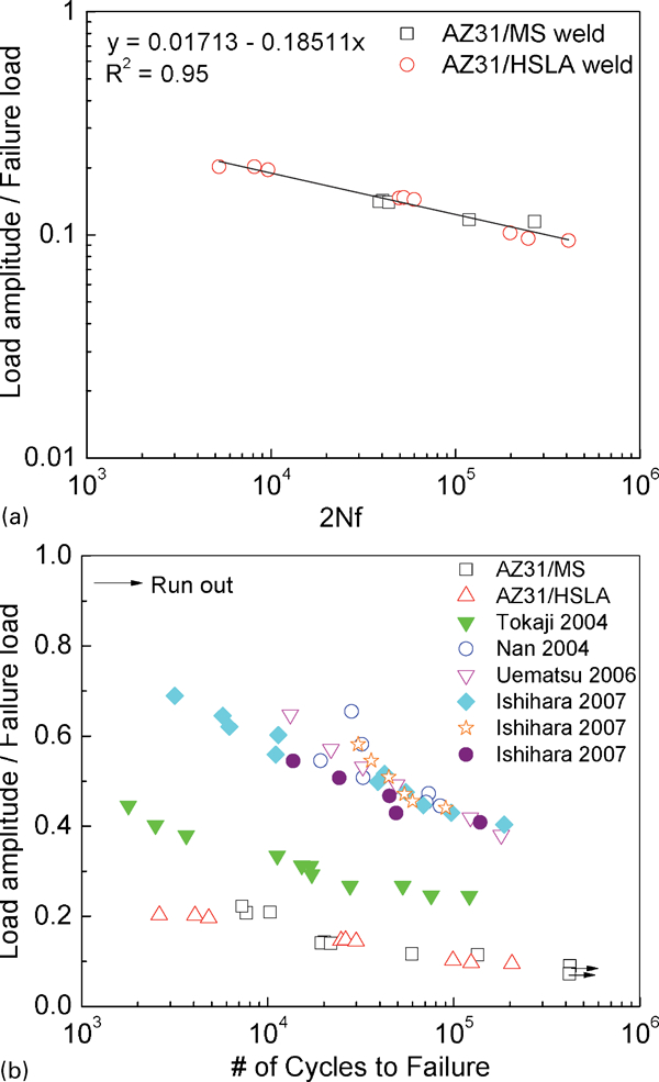
a Basquin plot for current Mg fatigue data and b S–N plot comparing fatigue performance of unwelded AZ31 specimens from literature against current results: significant difference in fatigue performance could be noted
In the present work, the strength of the top Mg sheet could not be determined because of the lap weld configuration. However, literature data on the FSW of AZ31 alloy can give an idea about the possible yield and tensile strength of the top Mg sheet. Tensile test data of friction stir welded/processed (FSW/P) AZ31 alloy from the literature are summarised in Table 2.11– 18 Literature data indicate the tensile specimen geometry to be either transverse or longitudinal to the weld direction. In both cases, FSW/P AZ31 shows substantial softening in terms of both YS and TS. In general, YS of the transversely tested AZ31 specimens is noted to be ∼100 MPa. It can further be noted that the per cent elongation to failure drops significantly in the case of transversely tested tensile specimens. However, for longitudinal FSW/P tensile specimens, there is an improvement in per cent elongation to failure. The process of FSW results in fine equiaxed grains inside the nugget due to the combined action of severe deformation and elevated temperature. As a result, a high level of tensile elongation is expected, especially when FSW/P Mg alloys are known to exhibit very weak Hall–Petch behaviour.16 However, a drop in both the yield strength and the elongation value in the case of transverse tensile specimens indicates the presence of a weak region across the weld cross-section. The weaker region is noted to be present on the advancing side, as suggested by the literature data (Table 2). The exact cause of such a drop in ductility is unknown. Lim et al. 11 linked such behaviour to entrapped oxide during FSW. On the other hand, Woo et al. 12 related such an event to a change in the texture pattern of the underlying Mg grains.
Summary of YS/TS and % El of FSW/P AZ31 from literature*
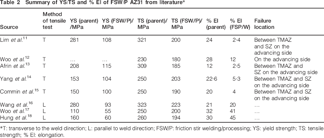
*T: transverse to the weld direction; L: parallel to weld direction; FSW/P: friction stir welding/processing; YS: yield strength; TS: tensile strength; % El: elongation.
Therefore, substantial softening of the top Mg sheet weld nugget can be safely assumed from the literature data. However, even with significant softening of the top Mg sheet, Fig. 2b shows that the load amplitude/failure load ratio values at a given Nf are considerably lower than that of a comparable material (i.e. refer to Tokaji et al. 10 data). One of the reasons for such a difference is due to the comparison of the data obtained at two different R values. While the data for Tokaji et al. are at R = −1, the current test used R = 0·1 for all the specimens. The use of a positive R ratio leads to a reduction in the load amplitude. The other and likely more important reason is the nature of the weld interface. Figure 3a depicts a schematic drawing of the lap shear specimens used in the current study, where the fracture path has been marked. A close-up image of the interface, shown in Fig. 3b, reveals the presence of ‘hook’-like features at the Mg/steel interface, marked by dashed circles. It is further observed from Fig. 3b that the FSW tool deforms the bottom steel sheet, and as a result, the ‘hook’-like features form around the tool pin. The presence of such features introduces stress concentration sites inside the top Mg sheet weld nugget. An examination of the failed specimens confirmed that the final fatigue crack was along one such ‘hook’ feature and, predominantly, on the advancing side of the welded top Mg sheet. Therefore, it can be concluded that the presence of the ‘hook’-like feature led to failures at lower nominal loads due to the stress concentration effect, whereas the presence of a weaker region along the advancing side led to localisation of fatigue cracks on the advancing side, which is in agreement with the literature findings.
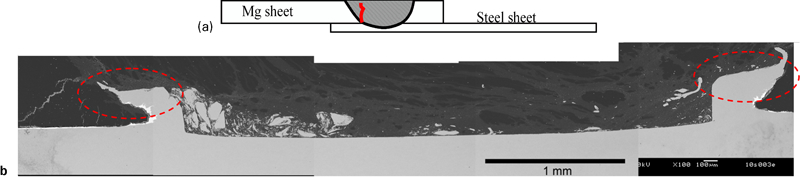
a schematic drawing of lap shear specimen cross-section used in current study (red line depicts fracture path) and b close-up of Mg/steel welded interface (presence of ‘hook’-like feature on two sides can easily be noticed, marked by ‘dashed’ circles)
Examination of the fracture surface via SEM revealed typical fatigue fracture features. An SEM image of the fracture surface of a specimen with Nf = 205 622 cycles is shown in Fig. 4a. Crack initiation, which is shown by the white arrow on the top left corner of the image, is found to be adjacent to the hook feature (Fig. 4b). Following initiation, the crack moved along the Mg/steel interface, resulting in a smooth fracture surface (between the two dashed white lines). The initial crack is noted to have advanced at a considerable distance along the specimen width. However, as the main crack propagates, numerous secondary cracks start appearing, each forming a ‘lip’-like feature. Closer examination of one such secondary crack reveals the presence of voids (shown by the dashed circle) along the Mg/steel interface (Fig. 4c). The same voids have been shown by other white arrows on the lower magnification image (Fig. 4a). The creation of such voids along the Mg/steel welded interface is possibly related to the presence of a solidification microstructure along the Mg/steel interface. As it has been shown previously by Jana et al., 4 the top Zn coating present on the bottom steel sheet melts from the process heat and subsequently dissolves Mg from the top sheet. However, this Zn rich liquid alloy gets squeezed out laterally because of the forging action of the friction stir tool and solidifies mostly along the ‘hook’ feature. The formation of a solidification product leads to the creation of porosity at a few locations along the Mg/steel welded interface, which act as secondary crack nucleation sites. Further examination around the ‘lip’-like fracture surface showed the presence of coarse striation patterns (Fig. 4d). The final failure took place through ductile rupture evident by the dimples (Fig. 4e). The area that went through ductile rupture has been marked by the dashed black line.
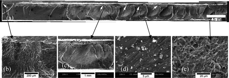
a image (SEM) of Mg fracture surface, b main crack initiation site, c presence of void highlighted by red circle at one of secondary cracks, d striation pattern on one of ‘lip’ features and e presence of dimples on final fracture surface (refer to text for complete details)
Conclusions
The present results indicate that the performance of friction stir welded joints under fatigue load is limited due to ‘hook’-like features, formed at the Mg/steel interface, which act as stress raisers, and the presence of Zn–Mg solidification product along the joint interface leading to the creation of voids. It would be worthwhile to study the fatigue performance of Mg/steel friction stir welded joints, where the bottom steel will not have any Zn coating, and therefore, the detrimental effect of solidification porosity could be avoided.
Footnotes
Acknowledgements
This manuscript has been authored by Battelle Memorial Institute, Pacific Northwest Division, under contract no. DE-AC05-76RL01830 with the US Department of Energy. The publisher, by accepting the article for publication, acknowledges that the US Government retains a non-exclusive, paid-up, irrevocable, worldwide license to publish or reproduce the published form of this manuscript, or allow others to do so, for US Government purposes.