
Abstract
Friction stir lap welding was applied to AZ31 magnesium alloy sheets to investigate the effect of tool designs and welding variables on top sheet thinning. Three tools with different shoulder designs were used. Sheet thinning aroused by the hooking or cold lap feature was quantified, and the lap shear fracture load of the joints was evaluated and correlated with the effective top sheet thickness. The tool geometry has a significant effect on the morphology and extent of both hooking and cold lap features, as well as welding variables such as welding pitch and plunge depth. The morphology and extent of these features influenced the effective top sheet thickness, which exhibited a linear relationship with the unit width fracture load via the welded material strength. High fracture loads can be achieved by suppressing the hooking and cold lap features as well as by strengthening the material in the nugget.
Introduction
Mass savings in the automotive industry is becoming increasingly important and can be enhanced using light weight magnesium alloys for structural applications.1 Problems with conventional welding techniques limit the expansion of using magnesium alloys in the industry. Friction stir welding (FSW), developed by TWI, UK, in 1991, is a novel solid state joining technique.2 In this process, a tool consisting of a shoulder and a protruding pin is plunged, rotated and traversed along the joint line. The heat generated by friction between the FSW tool and the surrounding material softens the material around the tool. The material under the stresses applied by the rotating tool then deforms and is transported around the tool into the wake of the pin. Thus, interfaces within the stir zone are broken up, and joining of the workpiece ensues.3
The strength of friction stir lap joints is affected mainly by macro features (the hooking or cold lap feature), which are in turn dominated by a combination of tool geometry and welding parameters. The macro features act to reduce the load carrying capacity of the joint and/or affect crack initiation and propagation.4– 6 Dissimilar material joints exhibit a greater propensity for these macro features.7, 8 Therefore, the design of the FSW tool is an important process variable as it affects both frictional heat generation and material flow during the FSW process.3, 9, 10 Control of the faying surface in friction stir lap welding was also attempted by modification of the commonly used threaded tool design. The addition of flats on the threaded pin has been found to enhance the local plastic deformation around the pin, and it has been suggested that the flats on the threaded pin act as pedals to generate local turbulence in the plasticised material flow.11, 12
Limited attention has been given to the friction stir lap welding of magnesium alloys, although lap welding is the most common weld configuration for automotive and aerospace industries. Yang et al. 13 carried out a comprehensive study of pin feature effects on the hooking formation and weld strength of AZ31 magnesium alloy. Cao and Jahazi14 investigated the effect of tool rotation rate and pin length on defect formation and mechanical properties of AZ31. In this paper, three tools with different tool shoulder diameters or features but the same triflat pin were used to evaluate the effect of shoulder geometry as well as welding variables on the top sheet thinning and tensile shear properties of AZ31 magnesium alloy lap joints.
Experimental
A commercial grade AZ31-H24 magnesium alloy having a thickness of 2·0 mm was the material chosen for the current study. An MTS I-Stir PDS Intelligent five-axis FSW system was used to make friction stir lap joints. Three different tool designs (presented in Fig. 1) were employed: (1) tool A, a convex scroll shoulder with 13 mm diameter and 3·5 mm long triflat threaded pin with 4·7 mm pin tip diameter and 6·0 mm pin root; (2) tool B, a concave tool shoulder with the same shoulder diameter and pin feature as tool A; and (3) tool C, a slightly reduced scale of tool B with 12 mm shoulder diameter. Tools were applied on overlapped AZ31 sheets with a rotation rate of 2000, 2200 or 2400 rev min−1 and a traverse speed of 2·75, 4·58, 6·67 or 7·50 mm s−1.
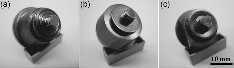
Macro images of FSW tools used in present study
An Instron testing machine was used to evaluate at least five lap shear specimens for each welding condition in order to obtain a representative average maximum fracture load. All specimens having a width of 38·1 mm were pulled at a crosshead speed of 0·02 mm s−1. During the test, samples were aligned using 2 mm AZ31 spacers in the clamping grips. In addition to mechanical testing, the lap joints were cross-sectioned along the transverse direction, mounted and polished with 1 μm finish for metallographic study. Specimens for electron backscatter diffraction (EBSD) study were further fine polished with 0·05 μm colloidal silica. The EBSD data were collected with a Leo 1450VP scanning electron microscope operating at 15 kV and a TSL Hikari high speed camera coupled with the TSL image acquisition system. The texture and microstructure parameters were determined using TSL v5·3 software.
Results and discussion
Weld cross-section and microstructure
Figure 2 presents cross-sections of AZ31 friction stir lap joints made using tools A, B and C. Only selected tool rotation rate and traverse speed combinations are presented to compare the effect shoulder geometries had upon macro features of the welds. Details of plunge depth are not specified because it does not influence the overall morphology of macro features based on the observation of each individual cross-section but does affect the extent of macro features. An asymmetric shape of the FSW nuggets is observed for all lap joints due to the difference in the relative motion of the tool with respect to the workpiece.4 The faying surface on the advancing side (AS) generally attains a hook shape and is therefore commonly known as the hooking feature. The faying surface on the retreating side (RS) is prone to extend across the nugget towards the AS. This feature is commonly known as the cold lap feature, which can end within the nugget or extend up to the hooking feature on the AS.
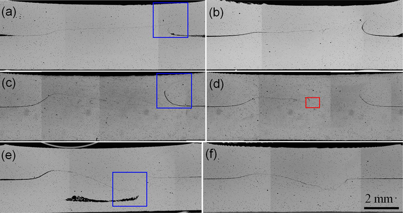
Effect of shoulder geometries and welding parameters on macro features of lap joints made using a, b tool A, c, d tool B and e, f tool C: welding parameters were a, c, e 2000 rev min−1, 4·58 mm s−1 and b, d, f 2200 rev min−1, 7·50 mm s−1; advancing side is on right hand side of each photo
Tool features influence the morphology of the hooking and cold lap features. The faying surface on the AS generally bends upwards along the nugget boundary, forming the hooking feature highlighted in Fig. 3a and b. However, the faying surface on the AS has been extended downwards for tool C, as highlighted in Fig. 3c. The upward or downward bending of the hooking is related to the horizontal and vertical material flow. During FSW, the material in front of the tool is driven upward. The upward moving material on the leading side then sweeps around the pin in the rotation direction;15– 17 however, on the trailing side, the layer rotating with the tool is decelerated and gets deposited in the void in the wake of the pin.16 The upward motion of the material on the leading edge induces the upward bent hooking feature. The downward hooking feature is mainly related to void formation as a result of insufficient material deposition in the wake of the pin and the subsequent shoulder forging effect. It is worth noting that the smaller tool shoulder for tool C limits the overall control on restricting material from leaving the process zone, as well as the frictional heat generation, which is also related to the void formation and less mixing in the nugget. The cold lap feature on the RS is relatively complex and generally extends across the nugget towards the AS.13 For tool A, the cold lap feature exhibits a gradual upward climb until it approaches the hooking on the AS (Fig. 3a). The cold lap feature becomes discontinuous once a relatively high tool traverse speed was used. For tool B, the cold lap feature shows a milder gradient; first gradually climbing, then it is deflected slightly downwards into the stir zone. In contrast to the results using tool A, the cold lap feature for tool B becomes more dispersed when approaching the weld centreline, which indicates a better material mixing. For tool C, the cold lap feature again first lifts up, then is deflected downwards into the stir zone and even penetrates into the stir zone further towards the AS. Unlike tools A and B, tool C generates a continuous interface that leads to significant joint strength reduction and is eliminated from further discussion.
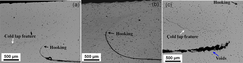
Macro features obtained for a tool A, b tool B and c tool C
Figure 4 is a pair of EBSD inverse pole figure maps of the as received and friction stir lap welded AZ31 sampled from the centre of the nugget, refer to the red box in Fig. 2d. Figure 4a represents the as received AZ31 material microstructure, which is a mixture of slightly elongated coarse grains and equiaxed fine grains. Figure 4b represents the weld nugget microstructure of AZ31 made at 2200 rev min−1 and 7·50 mm s−1, which corresponds to the highest fracture load achieved in current study. Compared with the as received material, a more uniform grain structure with an average grain size of 8·6±4·2 μm was achieved as a result of dynamic recrystallisation and possible grain growth.18– 20 A 90° rotation of the c axes of grains was noted after FSW, with most of the grains having their 〈0001〉 direction parallel to the normal of the cross-section. This is consistent with previous reports and is attributed to the intense shear deformation during FSW.21– 24
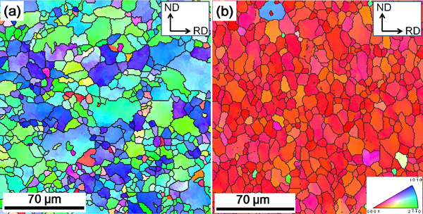
Electron backscatter diffraction inverse pole figure maps of a as received and b friction stir lap welded AZ31
Effect of welding variables on top sheet thinning
Top sheet thinning becomes critical when friction stir lap joints are implemented in load bearing components. To quantify the thinning under different welding parameters, an effective top sheet thickness (EST) was used. The EST is defined as the minimum vertical distance from the hooking or cold lap feature to the top surface (as schematically shown in Fig. 5). Figure 6 presents the effect of shoulder plunge depth on the thinning of the top sheet for tools A and B. The actual shoulder plunge depth was measured from the cross-section of the joints and substituted the programmed plunge depth in our analysis. Optimum tool rotation rates and traverse speeds were held at 2000 rev min−1 and 4·58 mm s−1 for tool A and 2200 rev min−1 and 7·50 mm s−1 for tool B. Results indicate that the EST on both AS and RS decreases with the increase in shoulder plunge depth. The overall reduction in EST is approximately equivalent to the increment of shoulder plunge depth except for the negligible variation for tool A on the AS. We attribute this to the fact that the change of EST at various plunge depths is mainly due to the thinning introduced by the indentation left by the shoulder on the top sheet surface rather than the vertical material flow induced fluctuation. The larger variation on EST between the AS and the RS for tool A than that for tool B indicates more vertical material flow for tool A as a result of the convex scroll shoulder feature.
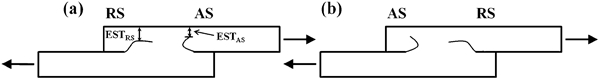
Schematic of a AS and b RS loading configurations of friction stir lap joints
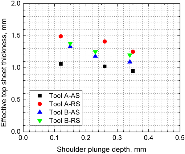
Effect of shoulder plunge depth on top sheet thinning for tools A and B
Another variable affecting the EST is the welding pitch, which represents the distance travelled by the tool along the welding direction in one revolution. Figure 7 presents the welding pitch on EST when tool A was used. Results indicate a likely linear relationship between the welding pitch and the EST and similar slopes for the AS and RS separately, which might suggest that the welding pitch has an equivalent effect on the vertical material flow for both AS and RS. The current observation is consistent with the literature reporting on FSW of Al alloys showing that increasing the rotation rate and decreasing the travel speed (same effect as reducing the welding pitch) of the tool lead to increased thinning in the top sheet.4, 5, 7 Yadava et al. 5 suggested that a higher rotation rate increases the horizontal and vertical material movements for a given welding pitch. The linear relationship in the current study indicates that the slight variation in tool rotation rate (200 rev min−1) was not adequate to introduce significant variation on vertical material flow.
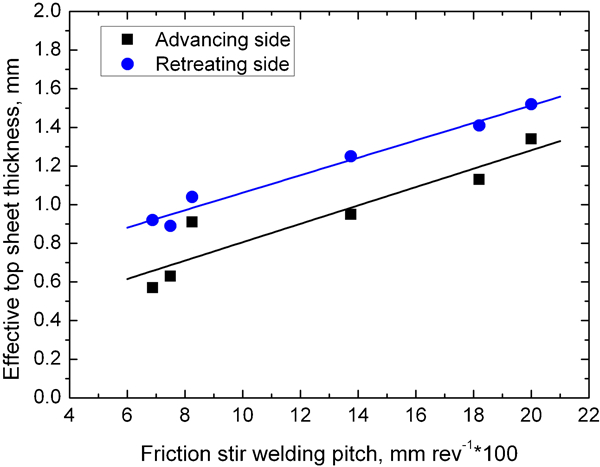
Effective top sheet thickness as function of welding pitch for tool A
Lap shear fracture load of friction stir lap joints
Because of the characteristic profiles of the hooking and cold lap features, Cederqvist and Reynolds4 suggested that the friction stir lap joints can be loaded in two different loading configurations: (1) AS loading and (2) RS loading, as schematically shown in Fig. 5.
Figure 8 presents the fracture load per unit width of joints made using tools A and B and tested in both AS and RS loaded configurations. Given that different welding parameter combinations were used, the difference in lap shear strength between the AS and RS loadings is prominent for both tools with a significantly higher average maximum fracture load under RS loading. Careful examination of fracture paths indicated that crack propagation under AS loading (refer to the blue arrows in the inserts of Fig. 8) occurred along the hooking feature for both tools A and B. However, crack propagation under RS loading (refer to the black arrows in the inserts of Fig. 8) was completely different between tools A and B. For Tool A, the crack propagated along the cold lap feature towards the AS and fractured on the AS. However, for tool B, once the crack reached the peak of the cold lap feature, it was forced to propagate directly through the top sheet instead of following the cold lap feature, and the specimen correspondingly fractured on the RS.
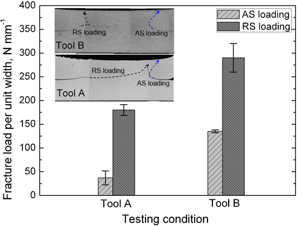
Fracture load per unit width of friction stir lap joints under AS and RS loadings: welding parameters were 2000 rev min−1, 4·58 mm s−1 for tool A and 2200 rev min−1, 7·50 mm s−1 for tool B; crack propagation paths during AS and RS loading for both tools A and B are included as inserts
The phenomenon of higher fracture load in RS loading compared to AS loading has been reported by many researchers.4– 6, 13 To explain this, one can refer to the schematic of macro features presented in Fig. 5. Regardless of which loading configuration was used, the top sheet underwent a higher tensile stress than the bottom sheet because of top sheet thinning, which explains why fracture was always observed at the top sheet. During AS loading (Fig. 5a), the maximum shear stress was achieved at the top sheet on the AS. The sharp curved character of the hooking feature introduced a significant stress concentration at the tip of the hook and promoted easy crack propagation along the hooking feature as the applied load increased. On the other hand, a maximum stress occurred at the top sheet but on the RS during RS loading (Fig. 5b). The gradual climb (tool A) or slightly upward then downward movement (tool B) of the cold lap feature during RS loading significantly reduced the stress concentration and retarded the crack propagation as compared to AS loading. Therefore, both the smaller EST (Figs. 6 and 7) and higher stress concentration on the AS lead to significantly lower fracture loads during AS loading compared to RS loading. The highly dispersed character of the cold lap feature for tool B further strengthens the joints by deviating crack propagation during RS loading.
Another factor that could influence the fracture load and fracture path is the crystallographic texture. Deformation of magnesium alloys exhibits a significant dependence of texture because of the significantly lower critical resolved shear stress for basal slip than that for non-basal slip.25 Figure 9 is a set of EBSD image quality maps highlighting the hooking and cold lap features of the lap joints shown in Fig. 2d. It is worth noting that the grey or dark curve region (hooking and cold lap features) only indicates low confidence indexing during EBSD data acquisition because of the existence of magnesium oxide. Orientations of individual crystals beside the hooking and cold lap features are embedded. All grains neighbouring the hooking feature and in front of the hooking tip align their basal planes to the orientation of the hooking feature, which lowers the required stress needed to initiate and propagate a crack during AS loading since deformation can be preferential along the easiest basal slip planes. The texture also explains the observed fracture paths (refer to inserts in Fig. 8) for the AS loaded specimens from a metallurgical viewpoint. However, most of the grains beside the cold lap feature have their prismatic planes roughly parallel to the curved cold lap feature and their basal planes tilted slightly off the normal to the cold lap feature towards the lower left hand corner of the cross-section (refer to Fig. 9b). During RS loading, crack propagation along the cold lap feature requires difficult prismatic slip to accommodate the deformation to a level depending on the dispersion of the magnesium oxide film. On the other hand, crack propagation through the thickness of the upper sheet (actual fracture path) can be fulfilled only by a synergy of deformation on both basal and non-basal planes based on the crystal orientation. Thus, the required non-basal deformation for crack propagation during RS loading drives a higher stress level.
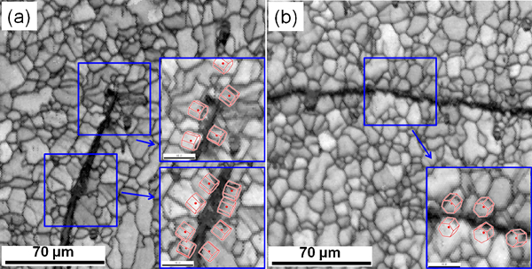
Electron backscatter diffraction image quality maps of a hooking and b cold lap feature of lap joints made using tool B with 2200 rev min−1, 7·50 mm s−1
As discussed previously, the extent, orientation and continuity of the hooking and cold lap features, as well as local texture, have a significant effect on the stress concentration or crack propagation. Dependent upon the actual combination of these factors, the crack can propagate along the cold lap feature to the hooking feature (shear fracture) or propagate towards the upper or lower sheet (mainly tensile fracture). Given that the loading condition is complex during lap shear testing as a result of specimen reorientation, which generally introduces bending to the shear test, a tensile dominated fracture mode is necessary for high fracture loads.
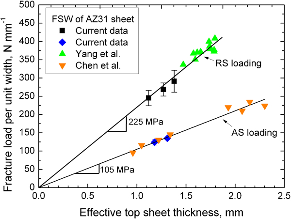
Figure 10 is a plot of fracture load per unit width as a function of EST for tool B in both RS and AS loading conditions. During RS loading, the crack propagated along the cold lap feature and fracture occurred in the upper sheet directly above the peak of the cold lap feature. Results show a gradual increase in fracture load with the EST. By comparing the current data for AZ31 with those reported for AZ31 by Yang et al. 13 using a similar tool (same tool geometry ratio), one finds that both data can be linearly fitted. The slope of the fitted line indicates the fracture strength of the material in the nugget region. Previous examinations of the tensile strength of friction stir processed AZ31-H24 magnesium alloys resulted in an ultimate tensile strength of ∼200 and 275 MPa along the welding direction and perpendicular to the welding direction respectively for a grain size range of about 3–10 μm.26 With the current welded material having an average grain size of ∼8·6 μm, the fracture strength of the current welds is expected to be in the range of 200–275 MPa, since these are the lower and upper bounds of tensile strength corresponding to the easy activation or full suppression of the basal slip. Specimens tested under AS loading also exhibit a linear relationship with the EST by comparing current data with those (similar hooking geometry) of Chen et al. 27 However, the fracture strength based on the best linear fit is significantly smaller than what can be inferred from previous defect free specimen tensile testing.26 The stress concentration at the tip of the hooking feature is likely the reason for the lower computed fracture strength for AS loading.
Conclusions
The effect of tool shoulder design and welding variables on the thinning of AZ31 magnesium alloy sheet during friction stir lap welding was studied. The following conclusions can be made.
The tool geometry has a significant effect on the morphology and extent of hooking and cold lap features. Tool B (concave shoulder) exhibits the best mixing effect on material flow, which introduces discontinuous and relatively flat cold lap features.
Welding variables such as welding pitch and plunge depth play a significant role in top sheet thinning. Increasing the welding pitch or reducing the plunge depth introduces less top sheet thinning and more effective top sheet thickness.
The EST exhibited a linear relationship with the fracture load per unit width via the strength of the welded material. Although the fracture load is mainly dominated by the macro features, a higher fracture load can be expected by suppressing the hooking and cold lap features, eliminating any stress concentration sites as well as strengthening material in the nugget region, such as grain size strengthening or texture strengthening.
Footnotes
Acknowledgements
The authors would like to acknowledge R. Kubic, Jr of GM R&D Centre for assistance with EBSD.