
Abstract
Dissimilar joints of magnesium alloys were obtained by friction stir welding. Detailed microstructure and texture examinations were performed on the joints. Significant difference in microtexture distribution and microstructural features is observed between crown and stir zones in the dissimilar joints. However, an overall effect of these factors on mechanical properties of layered joints is not obvious as both the up and middle samples present quite similar yield strength and strain hardening behaviour. Moreover, both samples fracture in the Mg–3Al–1Zn alloy side. The fracture of the middle sample starts at the boundary of transition and stir zones, while the up sample starts in the crown zone side.
Introduction
As one of the lightest structural materials, Mg alloys have wide potential applications in aerospace and automotive fields.1, 2 In order to widen the applications, it is important to study the welding performance of Mg alloys. Friction stir welding (FSW) is a solid state joining technique, which has some advantages in joining Mg alloys compared with conventional welding methods.3, 4 Friction stir welding process is finished under the hybrid effects of friction heat and force. Several distinct zones with different microstructures and microtextures can be distinguished in a joint because different thermomechanical histories are experienced at various regions.5–11 A FSW joint normally consists of base metal (BM), transition zone (TZ) and weld zone (WZ). The WZ can further be divided into crown zone (CZ) and stir zone (SZ), which corresponds to the upper and lower parts respectively. 11
Strong and complicated microtextures are usually formed in WZ of FSW Mg alloys.11–17 A recent study found that sampling design (whether includes the upper part of WZ or not) has significant influence on tensile property and fracture behaviour of FSW Mg joints. 11 This is related to the presence of a triple junction region in the interface of TZ, SZ side and CZ side in the advancing side (AS). Moreover, it was reported that texture is significantly different between CZ and SZ due to the quite different force and heat caused by relatively large cylindrical shoulder and small profiled pin respectively.11, 13 Therefore, it is expected that the upper and lower layers of WZ will behave differently under transverse tension. However, comparative studies of mechanical property of different layers and their microstructure evolution have limitedly been reported. 18 Therefore, the motivation of the present study is to examine the difference of microstructure and mechanical property among the different layers of FSW joints. Two layers of tensile samples are machined from dissimilar Mg joints including CZ and SZ respectively. The transverse tensile property and fracture behaviour are compared between the two samples. The microstructure and texture evolutions in CZ and SZ and the corresponding deformation mechanisms are analysed and compared.
Experimental
Hot rolled commercial AZ31 and cast ZK60 Mg alloy plates with an aged state of 175°C for 10 h were used as initial materials. The weld plates have thickness of 6 mm. Before welding, the plates were polished by abrasive paper and cleaned with acetone. Friction stir welding was conducted with a tool tilt angle of 2.5° at a rotation rate of 800 rev min− 1 and a welding speed of 100 mm min− 1. A cylindrical thread pin tool was used with a probe length of 5.45 mm. The shoulder and pin diameters of the tool were 15 and 5 mm respectively. The joint with ZK60 alloy in AS and AZ31 alloy in the retreating side (RS) was used for this study. Although only one set of welding parameter was reported here, it should be mentioned that changes in welding conditions may change the microstructure and tensile properties. 19
Two kinds of specimens for transverse tensile tests were machined from the joint. The design and dimensions of the specimens are shown in Fig. 1. The up sample was machined excluding SZ. The mid sample was machined excluding CZ and cut with ∼1 mm away from the bottom surface of FSW plates (Fig. 1a). The transverse tensile test was performed at a strain rate of 10− 3 s− 1 at room temperature. Each kind of test sample was repeated three times to get representative results. Optical (OM) and scanning electron microscopes (SEM) were used to examine microstructure evolution. Electron backscattered diffraction was used to analyse texture evolution in various regions of WZ. The step size of electron backscattered diffraction scanning was set as 1 μm. Pole figures were obtained based on a scan area of ∼150 × 150 μm.
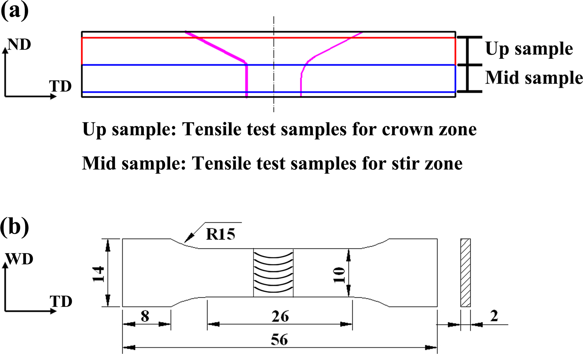
a sampling design; b sample dimensions
Results and discussion
Macrostructure of welds
The cross-section of the dissimilar joint is shown in Fig. 2. Two dashed lines represent the boundaries vertical to the WD in cross-sections. One separates WZ and TZ, and the other divides WZ into the upper and lower parts, named as CZ and SZ, respectively. Moreover, the boundary between CZ and SZ is obviously observed, which is beneficial for preparing the two types of samples in the present study. As measured using the ImageJ software, the depth of SZ varies along the TD, which are ∼3.44 mm in AS and 2.97 mm in RS. It indicated that the microstructure of WZ was asymmetric, which is related to the different severe plastic deformation and thermal cycle in asymmetric material flow. 20
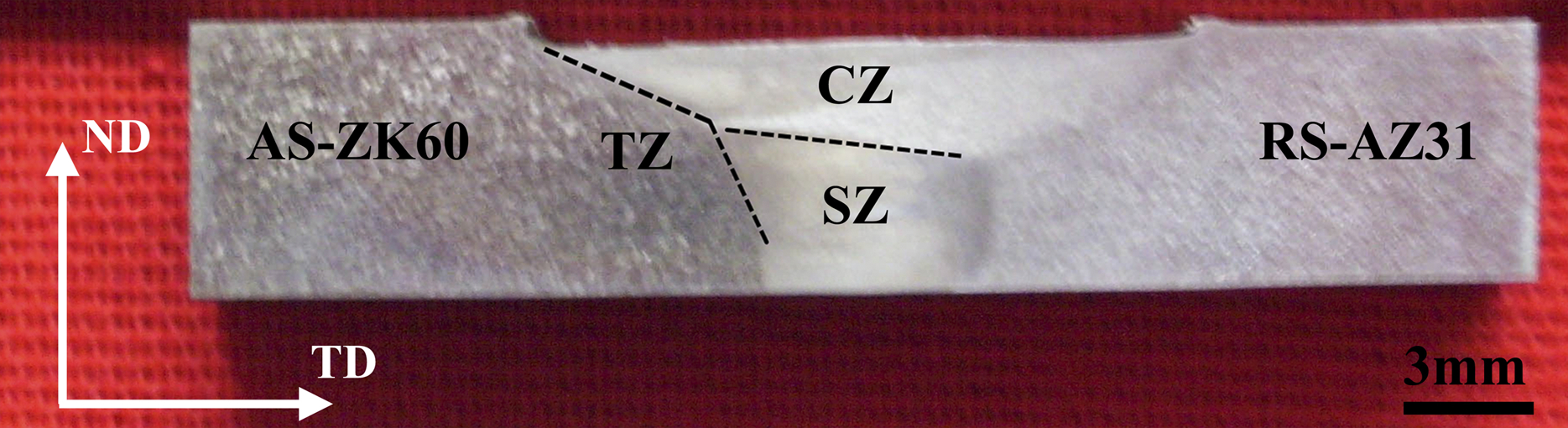
Macroscopic cross-sections of dissimilar joint of ZK60 and AZ31 Mg alloys
The OM is used to investigate the interfaces between TZ and WZ (including CZ and SZ) of the dissimilar joint in AS, and the results are shown in Fig. 3. A clear interface of TZ/WZ can be seen in AS, which is in agreement with previous publications.21–23 The observation implies that there is a drastic change of microstructure between WZ and TZ in AS. As is well known, the material is driven to rotate around stir tool along the rotation direction of the tool. As the material in AS flows forward to RS, the material undergoes rotary shear deformation, leading to a narrow shear layer on AS and abrupt microstructural transition between WZ and TZ. 21 However, the interfaces of TZ/CZ and TZ/SZ are differently angled (∼40 and ∼75° respectively) with respect to the TD. This may be attributed to the effect of shoulder. In addition to being sheared by stir pin, CZ experiences the compression of tool shoulder and thus produces different texture characteristic compared with SZ. Moreover, it is considered that the different angles of the interfaces of TZ/CZ and TZ/SZ with respect to the TD may have an effect on fracture behaviour of the two types of samples.
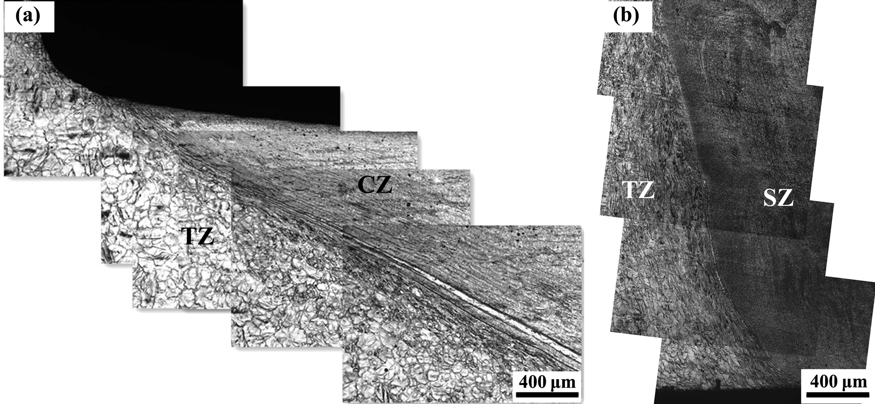
a interface between TZ and CZ; b interface between TZ and SZ
Microstructure and texture evolution
Figure 4 shows typical microstructure of various regions in the joint of ZK60 and AZ31 alloys. It is found that grain size is different in weld zone. It is ∼9.6 ± 0.8 μm at SZ in the AZ31 side by a linear intercept method. It is even smaller (∼3.3 ± 0.4 μm) at SZ in the ZK60 side of ZK60/AZ31 joints. Significant grain refinement is obtained in SZ compared with the two kinds of base metal (∼75 ± 2.5 μm in ZK60-BM and ∼30.2 ± 1.0 μm in AZ31-BM), especially in the ZK60 side.11, 17 It has been reported that the Zr rich particles in ZK60 alloy played an important role in grain refinement.24–26 Moreover, the grain size of SZ is uniform in both ZK60 and AZ31 sides.

a CZ in ZK60 side; b CZ in AZ31 side; c SZ in ZK60 side; d SZ in AZ31 side
Some banded structure (inclined to the TD at an angle ∼20°) is found in CZ both in ZK60 and AZ31 sides. This is related to the material flow around the tool in the direction of tool rotation during FSW. 21 Thus, banded structure may be formed in the upper part of WZ due to relatively large cylindrical shoulder and thread of pin. The average grain size of CZ is ∼5.3 ± 0.3 μm in the ZK60 side, which is larger than that of SZ in the ZK60 side. A similar tendency was observed in the AZ31 side (∼11.4 ± 1.1 μm in CZ and ∼9.6 ± 0.8 μm in SZ). This is mainly attributed to the fact that more friction heat was caused in CZ by a relatively large cylindrical shoulder, while less was in SZ by profiled pin. 11
As reported before, the interface shape and microstructure is important for controlled dissimilar FSW joint. 27 To understand such features in the current sample, Fig. 5 presents a cross-sectional OM image of the dissimilar joint. It shows that there is a clear boundary between the two types of materials (ZK60 and AZ31). In the figure, ZK60 appears darker than AZ31 due to the difference in corrosion property related to their composition and grain size. It means that ZK60 and AZ31 are not completely mixed even in SZ. The SEM image of the region indicated by a square in Fig. 5 is shown in Fig. 6a. There is a clear boundary near the middle of the SEM image separating the left part from the right. The element contents of the square region were analysed by energy dispersive spectrometer (EDS) and are indicated in the squares. It further confirms that the left part with smaller grain size is mainly of ZK60, and the right part with larger grain size is of AZ31. In Fig. 6b, a line scan of EDS was performed from the left to the right side along the yellow line. It indicates that the composition change of Al and Zr is relatively sharp from ZK60 to AZ31, which again indicates that the two alloys are not completely mixed at the grain scale. However, there may be some diffusion of elements at the interface of the two materials.
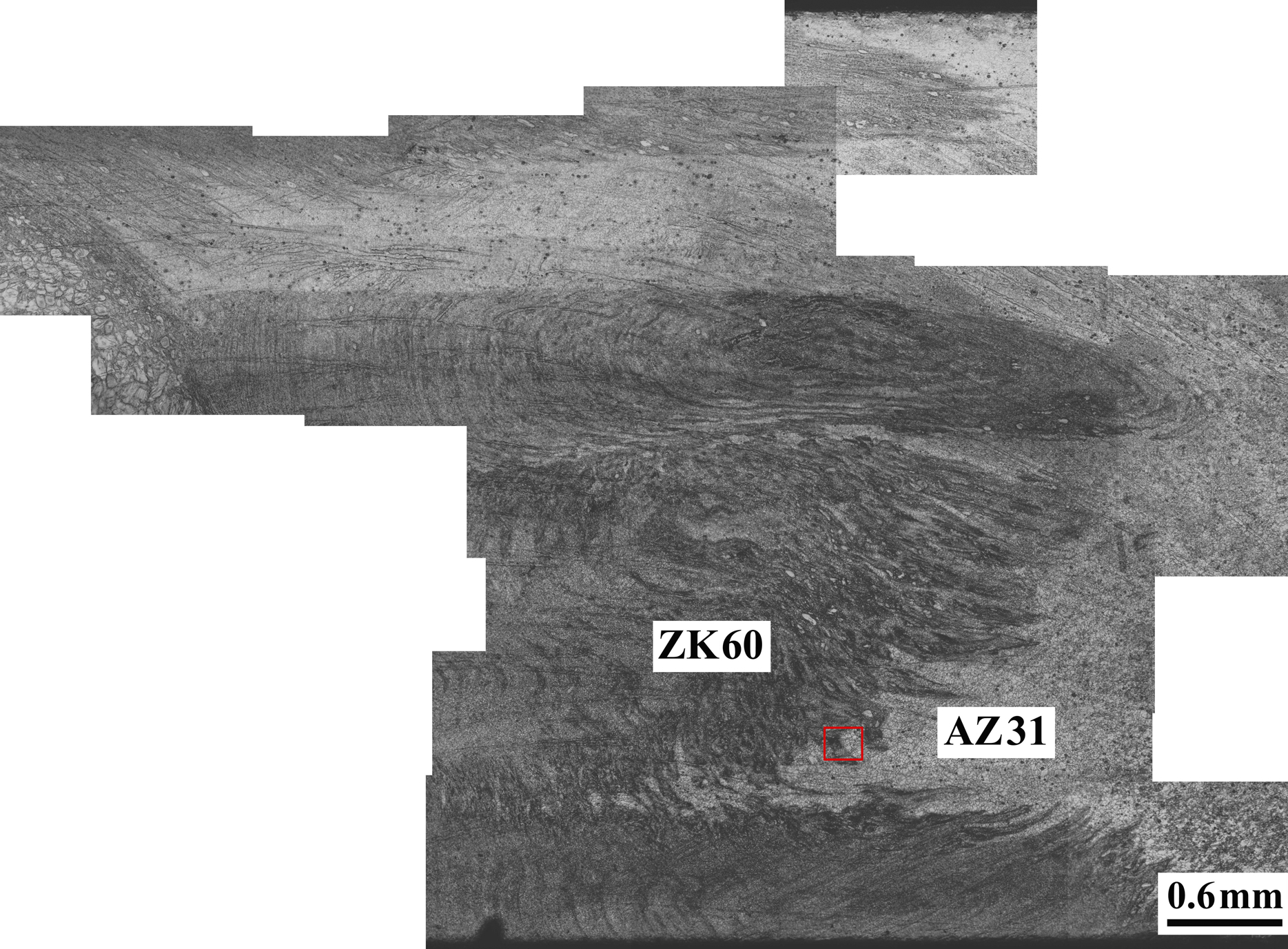
Cross-sectional OM image of dissimilar joint at SZ; squared region is further enlarged in Fig. 6a
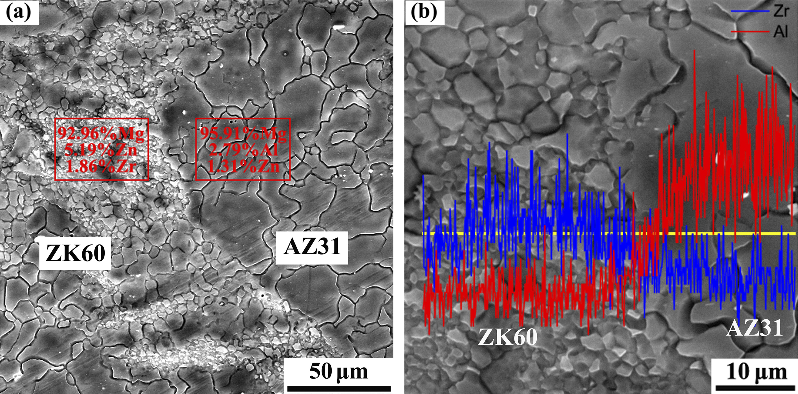
Image (SEM) of ZK60/AZ31 interface at SZ; element contents from squared regions are analysed by EDS in a and line scan is performed along yellow line in b
The microtexture evolution of WZ was studied. (0001) pole figures between the weld side and the weld centre are shown in Fig. 7. It shows that the c axis is inclined ∼24° to the WD and almost perpendicular to the TD (∼89°) in SZ centre, while it tilts ∼29° to the TD in the SZ side. The grains between the SZ side and the SZ centre are oriented with the c axis inclined ∼55° to the TD. In a previous study, Park et al. 15 have found that (0002) basal plane in SZ roughly surrounds the pin column surface of weld tool, which is consistent with the present result. In addition, the texture evolution in CZ presents a similar trend with that in SZ. The c axis gradually tilts from the WD to ND with the position moving from SZ to CZ. Specifically, the angle between the c axis of grains and the TD in the CZ centre and the CZ side is approximately 85 and 57° respectively. This means that the inclination angle of the c axis toward the TD is larger in SZ (∼60°) than that in CZ (∼28°) with the position moving from the centre to the side. The reason is ascribed to a strong force from the tool shoulder applied in the upper of WZ. 11 The above analysis indicates that, although the two materials (ZK60 and AZ31) are not completely mixed in SZ, the characteristic of texture distribution in SZ appears similar with AZ31/AZ31 joint.
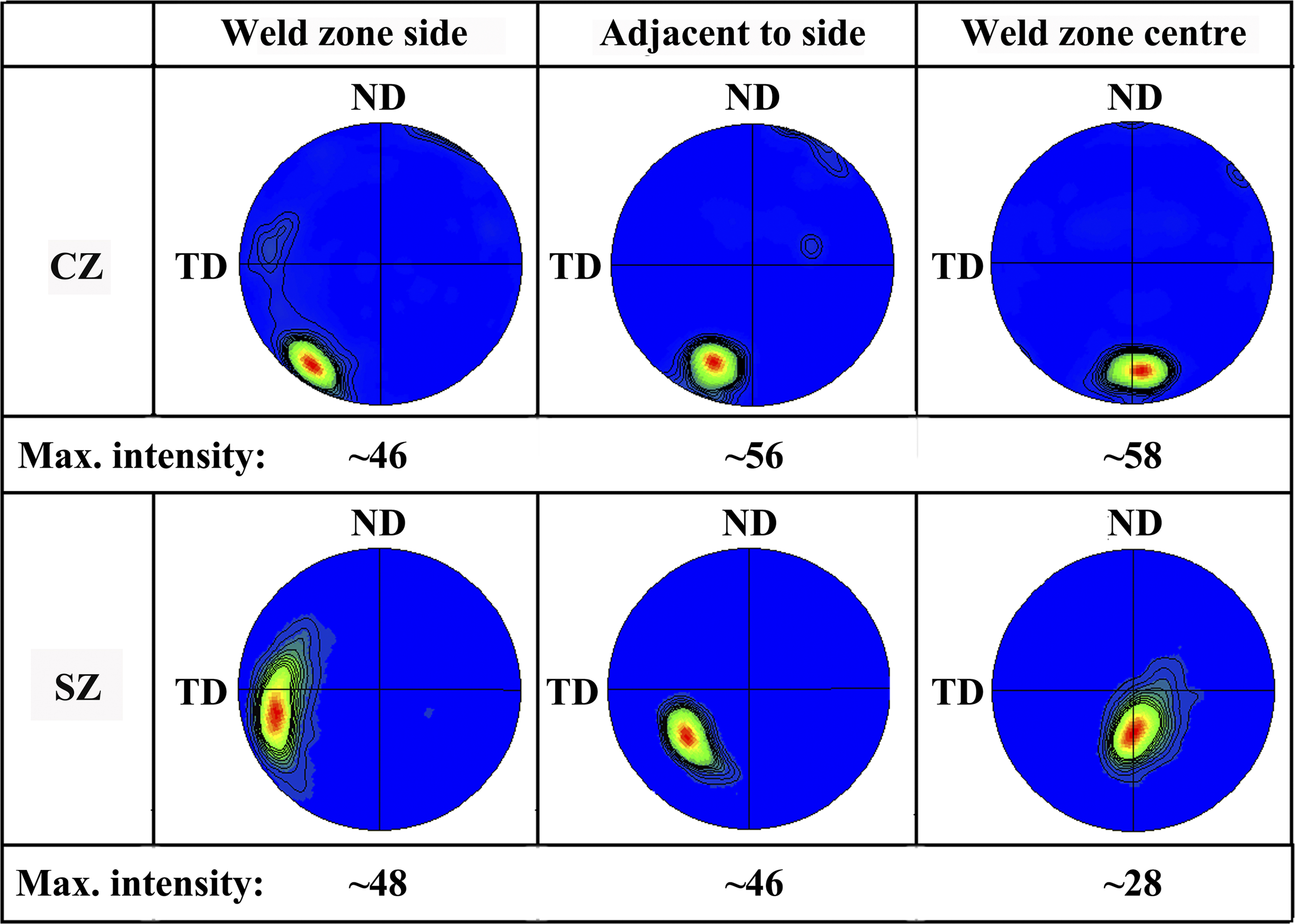
(0001) pole figures of various regions (from weld side to weld centre) in ZK60/AZ31 joints
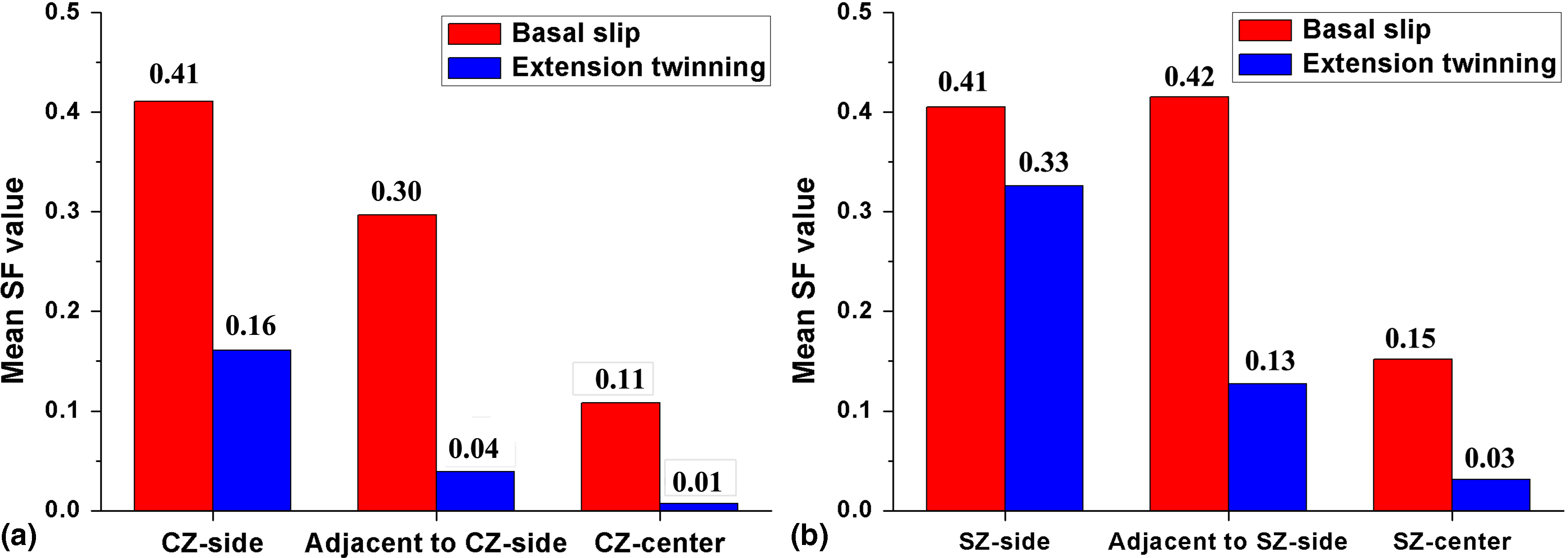
To understand the mechanism of plastic deformation in WZ during transverses tensile tests, the mean SF for basal slip and extension twinning were studied in various regions of CZ and SZ, and the results are shown in Fig. 8. It is seen that the mean SF for basal slip in the CZ side is very large (∼0.41), while the centre of CZ have a small mean SF ( < 0.3) for both basal slip and extension twinning. It implies that basal slip can be easily activated in the CZ side, while both basal slip and extension twinning are relatively hard to be activated at the centre region of CZ.
a CZ; b SZ
The SZ side has a large mean SF for basal slip and extension twinning, which is about 0.41 and 0.33 respectively. As the region beside the SZ side has a large mean SF for basal slip (∼0.42) and a small mean SF for extension twinning (∼0.13), it is named as a region easy to activate basal slip (EABS region) in the following. It can be confirmed that extension twinning is dominated in the SZ side, while basal slip is dominated in the EABS region.16, 28 By contrast, neither basal slip nor extension twinning is easily activated at the SZ centre. This observation is consistent with a few previous studies.11, 16, 17, 28
Mechanical properties and fracture mechanism
The results of transverse tensile tests are presented in Fig. 9a and Table 1. Although the grains are significantly refined in FSW Mg joints compared to that in BM, their tensile strength and elongation are not improved much compared with AZ31-BM (∼96.3 MPa) and are much lower than ZK60-BM (∼143.9 MPa). This is mainly due to the presence of a ‘soft’ region favourable for basal slip and extension twinning in FSW joint. Moreover, the yield strengths (YS) of the up and mid samples are similar, being 104 and 106 MPa respectively. The reason is discussed as follows. It is considered that dislocation density is roughly uniform throughout a weld. 15 The larger amount of second phase particles and smaller grains in SZ may lead to higher YS for the mid sample. However, the grains in the CZ side are in relatively hard orientation for extension twinning, which may cause an improvement of YS for the up sample. As a combined effect by texture distribution, grain size and second phase particles between the CZ side and the SZ side, the YS of the up sample is slightly smaller than that of the mid sample.
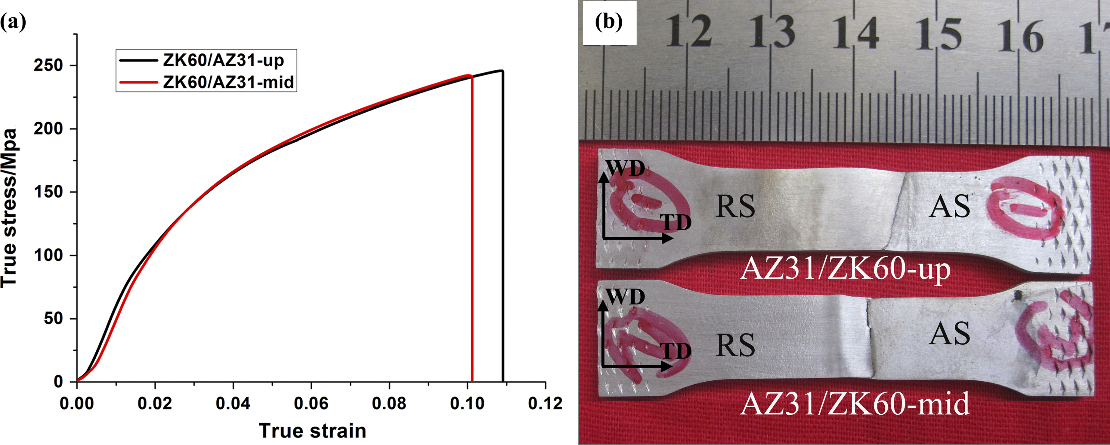
a stress–strain curves; b fracture positions
Mechanical properties of two kinds of tensile samples of FSW joints and as received plate
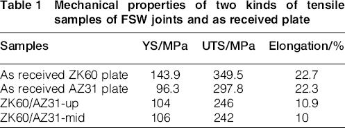
As shown in Table 1, the ultimate tensile strength (UTS) and elongation of the up and mid samples both decrease with respect to those of ZK60-BM and AZ31-BM. The reason is that there is a ‘weak’ region which is favourable for basal slip in the two types of samples. In addition, the UTS of the up sample is ∼246 MPa, which is slightly higher (by ∼4 MPa) than that of the mid sample (242 MPa). Moreover, the elongation to fracture of the up sample is ∼10.9%, which is also a little higher than that of the mid sample (10%). The reason can be attributed to the different texture distributions between the CZ and SZ sides. As mentioned above, extension twinning and basal slip can be easily activated in the SZ side. The different deformation mechanisms in the SZ side can cause deformation incompatibility and accelerate fracture for the mid sample. However, there should be no transition of deformation mechanism in the up sample. As a result, the UTS and elongation of the up sample are slightly higher than those of the mid sample.
Figure 9b shows the fractured specimens of the dissimilar FSW joints of ZK60 and AZ31 alloys. It can be seen that both the up and mid samples are necked and fractured in AZ31 side. This is mainly attributed to the fact that the AZ31 alloy is ‘soft’ compared with ZK60 alloy (see Table 1). Basal slip can be activated in CZ side, SZ side and EABS region, and it is more favourable in the AZ31 side due to the relatively larger grains. The activation of extension twinning and basal slip in the SZ side can cause deformation incompatibility and accelerate fracture in the mid sample. 17 Therefore, both the up and Mid samples can be likely fractured in AZ31 side. The fracture location of the two samples is slightly different. The fracture of the mid sample starts at the boundary of the TZ/SZ and propagates toward SZ. The similar phenomenon can be found in previous studies,11, 17 which is related to the change of deformation mechanism. However, the fracture of the up sample starts in the CZ side and propagates toward CZ (Fig. 9b). The reason is probably ascribed to the fact that basal slip can be easily activated in the CZ side. It implies that the different angles with respect to the TD for the interfaces of TZ/CZ and TZ/SZ may have effects on fracture behaviour of the up and mid samples.
Conclusions
Several conclusions could be made as follows.
The microstructure and texture distribution are significantly different between crown and stir zones. The grain size of the crown zone is larger than that of the stir zone. Texture tends to rotate from the transverse to the welding direction with the position moving from stir zone side to centre. Furthermore, it tends to tilt toward the normal direction in the crown zone compared with that in the stir zone. Such texture difference has influence on the activation of basal slip and especially of extension twinning. As confirmed from the Schmid factor analysis, extension twinning more likely occurs in the side of the stir zone than that of the crown zone. Clear interfaces of microstructure can be seen between transition and crown zones and between transition and stir zones in advancing side. Banded structure is also observed in the crown zone while less in the stir zone. The difference in texture, interface and banded structure between the up and middle samples should influence mechanical properties individually. However, an overall effect of the above factors is not obvious as both samples present quite similar yield strength and strain hardening behaviour. Both the up and middle samples fractured in the Mg–3Al–1Zn alloy side. The fracture of the middle sample starts at the boundary of transition zone/stir zone, while the up sample starts in the crown zone side. It implies that the different angles of transition zone/crown zone and transition zone/stir zone interfaces with respect to the transverse direction have some effect on fracture behaviour of the two types of samples.
Footnotes
Acknowledgements
This project was financially supported by the National Basic Research Program of China (‘973’ Project) (grant no. 2013CB632200) and the National Natural Science Foundation of China (project no. 51421001).