
Abstract
6061 aluminium alloy and AZ31B magnesium alloy was successfully joined together with the addition of Zn interlayer by gas tungsten arc welding assisted hybrid ultrasonic seam welding. The effects of Zn interlayer on the microstructure and mechanical properties of the joints were investigated in detail. The results indicated that the Zn interlayer could restrain the formation of brittle Mg–Al IMCs, which were replaced by Mg–Zn IMCs. The maximum lap strength of the joints with Zn interlayer was ∼16.25 MPa, which was ∼30 increase over the joints without Zn interlayer. All the joint failures occurred by the interface mode rather than the pullout mode at the Mg/Zn interface.
Introduction
The successful joining of dissimilar light materials of Al and Mg alloys is an advantage for producing lightweight structures, pushing forward the project of energy saving and emission reduction in the transportation and aerospace industries.1–3 In order to achieve a good combination of the properties of Mg and Al alloys, owing to their low density, high strength/weight ratio and damping capacity, welding reliability between Mg and Al alloys is required.4–6 Unfortunately, traditional fusion welding between Mg and Al alloys usually results in large amount of brittle Mg–Al intermetallic compounds (IMCs) formation, which deteriorates the mechanical property of the joint.7–10 Therefore, the solid state joining process gradually receives much attention for joining Mg and Al dissimilar metals.
Ultrasonic welding is a solid state joining process that involves forming welds by disruption of the interface oxide layer through deformation and thus, in principle, avoids liquid phase reactions. 11 The metallurgical defects, such as high levels of welding distortions and heat affected zone damage in fusion weld, can be typically avoided. 12 Recently, a number of papers have reported on the joining of dissimilar light metals by ultrasonic spot welding.13–15 A sound ultrasonic spot welding joints could be obtained at usual welding conditions. However, there have been surprisingly few researches in joining dissimilar metals by ultrasonic seam welding in spite of its higher efficiency and weld continuity characteristics. Conventional ultrasonic seam welding can only be applied to weld metal foils or thin plate ( < 0.5 mm in thickness) due to their lower welding energy of the power output.16,17 For welding of thick metal specimens, higher power welding systems are necessary. Unfortunately, the high ultrasonic power welding systems result in high cost and inconvenient manipulation of the ultrasonic equipment. In our previous research, gas tungsten arc welding (GTAW) was introduced into ultrasonic seam welding for the first time. The preceding GTAW with relatively low heat input can preheat the sheet metal to enhance the ultrasonic weldability. Thus, the solid state joining of 1 mm thick Al and Mg alloys sheets was accomplished without improving the ultrasonic power. 18 However, the hard and brittle IMCs of Al12Mg17 and Al3Mg2 were still formed, which preferentially acted as the source of microcracks to deteriorate the mechanical properties of the joint. In order to reduce the IMCs in Mg–Al dissimilar joint, interlayer was essential to be introduced into the weld. Zhang et al.19,20 and Liu et al.21–23 reported that Zn interlayer played an important role in joining of Al and Mg alloys by restraining the extreme reaction between Al and Mg atoms. The formation of Mg–Al IMCs was suppressed, and Mg–Zn binary IMCs formed. Therefore, the mechanical properties of joints were improved.
In the present paper, Zn interlayer was introduced into GTAW assisted hybrid ultrasonic seam welding to improve the mechanical properties of Mg–Al dissimilar joint by suppressing the formation of brittle Mg–Al IMCs. The selection of Zn interlayer was based on the Mg–Zn and Al–Zn binary phase diagrams and previous works. The Mg–Zn and Al–Zn binary phase diagrams showed that Zn could interact with Mg to form Mg–Zn IMCs, while Zn could be dissolved into Al to form solid solution. This study aimed to improve the joint strength by reducing the tendency for the formation of hard and brittle Mg–Al IMCs using Zn interlayer. The effects of Zn interlayer on the microstructure and mechanical properties of the joints were investigated in detail.
Experimental
The base materials employed in the experiment were Mg AZ31B and Al 6061 sheets with dimension of 150 mm × 60 mm × 1 mm. Pure Zn interlayer (0.2 mm thick) was used as interlayer between the Al and Mg alloy plate. Before welding, the plates and Zn interlayer were degreased and ground. The sheet specimens were clamped between the rotating sonotrode and the anvil in a lap configuration with an overlap distance of 20 mm, as shown in Fig. 1. It mainly consisted of ultrasonic seam welding system and GTAW system. The preceding GTAW torch was attached adjacent to rotating sonotrode and carried out with an angle of 45° adjacent to the joint. The rotating sonotrode tips had serrated surface to improve gripping of the lapped sheets. The GTAW assisted hybrid ultrasonic seam welding was carried out at GTAW current ranging from 15 to 35 A at a constant welding speed of 4 mm s− 1, pressure of 0.44 MPa, vibration frequency of 20 kHz and nominal power of 2 kW as listed in Table 1. The distance between arc and sonotrode was ∼15 mm.
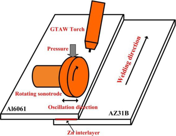
Schematic diagram of GTAW assisted hybrid ultrasonic seam welding system
Optimised welding parameters
The K type thermocouples of 0.5 mm diameter were used to measure the temperature profile during GTAW assisted hybrid ultrasonic seam welding. The thermocouples were embedded carefully at the centre of the weld. The metallurgical cross-section was observed by scanning electron microscope (SEM) equipped with energy dispersive X-ray spectroscopy (EDS) after standard grinding and polishing procedures. The Vickers hardness was measured along the transverse cross-section of the welded specimen using a load of 200 gf and dwell time of 10 s. Five 10 mm wide specimens perpendicular to welding direction were prepared and subjected to tensile testing machine with a speed of 0.5 mm min− 1 at room temperature. In addition, the fracture surface was examined by a SEM equipped with EDS. X-ray diffraction (XRD) was also carried out on the surface after tensile shear tests to investigate the phase evolution.
Results
Weld cross-section
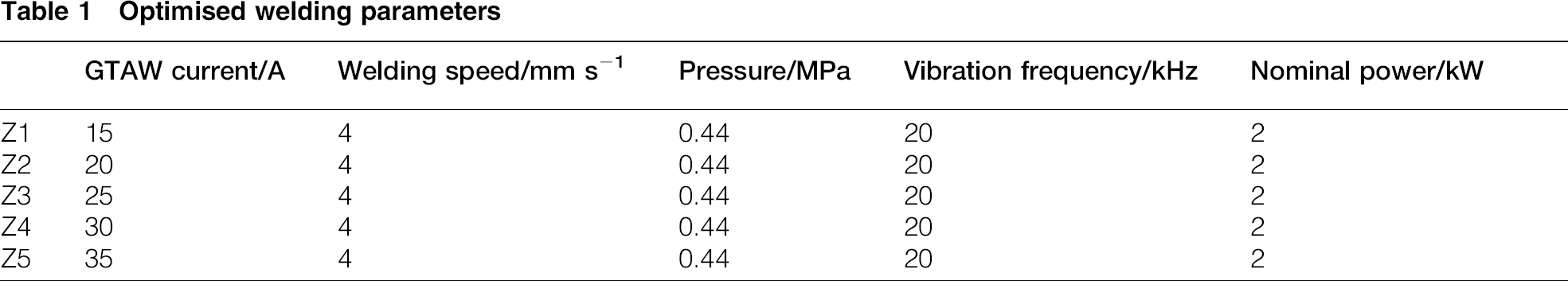
Figure 2 shows the typical SEM images of cross-section of the joints made at GTAW current of 30 A. The Al 6061 was presented on the upside, and the underside was Mg AZ31B. Zn interlayer placed between the Al 6061 and Mg AZ31B was uniform and compact. Obviously, a sound joint could be obtained and weld defects such as voids and microcracks were not observed. The joint consisted of two distinct interface zones: Al/Zn interface labelled as A and Mg/Zn interface labelled as B. The interface zones usually were the weak zone during the joining of dissimilar metals. Therefore, the microstructure characteristics of the interface zones should be investigated emphatically in the following sections respectively.
SEM images of cross-section of typical joint
Microstructure evolution of interface zones
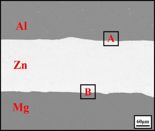
Figure 3 shows the SEM backscattered electron micrographs of the Al/Zn interface (label as A in Fig. 2) for different GTAW current. At lower GTAW current of 15 A, there was no continuous and stable reaction layer formed along the Al/Zn interface. The absence of the continuous reaction layer was attributed to the insufficient temperature for the chemical reaction and interdiffusion between Al and Zn atoms. 24 As the GTAW current increased to 20 and 25 A, the interface temperature rose and the interdiffusion was enhanced. The thickness of reaction layer rose from 4 μm for GTAW current of 20 A to 10 μm with GTAW current of 25 A and to 40 μm at GTAW current of 30 A. According to Al–Zn binary phase diagram as shown in Fig. 5a, it could be assured that the extensive solubility of Zn in Al was 67 at-. In addition, there was low melting point Al–Zn eutectic reaction at 381°C. Therefore, it could be indicated that the Al–Zn eutectic structure and Zn based solution with excellent plasticity and toughness was presented in the Al–Zn interface.
SEM images of Al/Zn interface at GTAW current of a 15 A, b 20 A, c 25 A and d 30 A
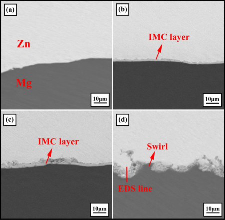
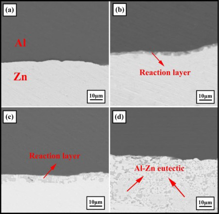
SEM images of Mg/Zn interface at GTAW current of a 15 A, b 20 A, c 25 A and d 30 A
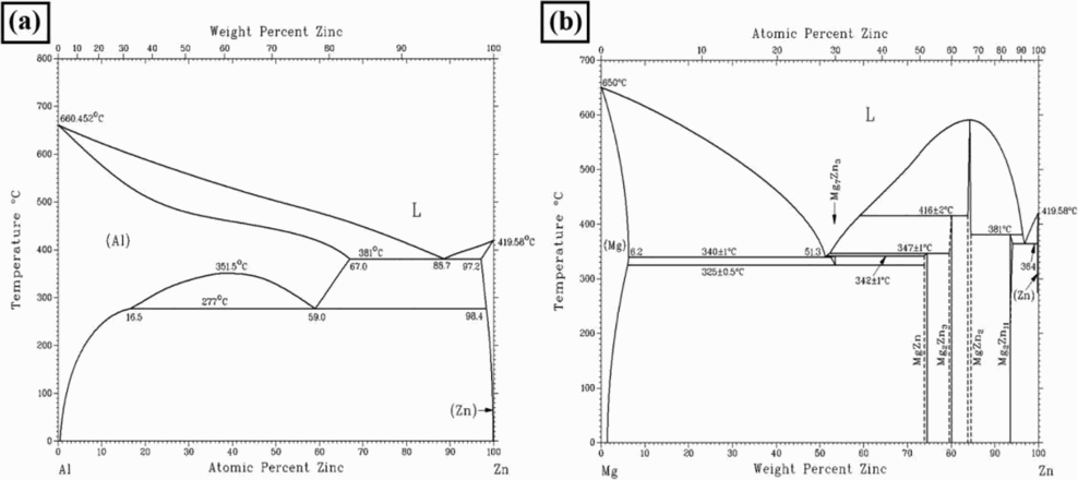
Binary phase diagram: a Al–Zn phase diagram; b Mg–Zn phase diagram
Figure 4 illustrates the SEM backscattered electron micrographs of the Mg/Zn interface (label as B in Fig. 2) developed with increasing GTAW current. At the low GTAW current, the weld join line still remained macroscopically flat. However, as the GTAW current increased to 30 A, a convoluted wave- or swirl-like structure was observed under the action of heavy plastic deformation. These structures could lead to a mechanical interlocking and therefore enhance the mechanical property of the joint. With GTAW current of 15 A, there was no visible reaction layer in the Mg–Zn interface. That was because the temperature was not yet risen sufficiently for the chemical reaction. 24 Comparing Fig. 4b and c, the reaction layer continued to increase uniformly in thickness. With increasing the GTAW current, the thickness of reaction layer grew from 3 μm at GTAW current of 20 A to 5 μm with GTAW current of 25 A and to 8 μm at GTAW current of 30 A. To identify the generation of phases in the reaction layer, EDS line analysis of the Mg–Zn interface at GTAW current of 30 A has been performed and the result was shown in Fig. 6. It could be seen that there was 4.5 μm wide platform, which indicated the existence of Mg–Zn IMCs. It was known that several Mg–Zn IMCs such as Mg7Zn3, MgZn, Mg2Zn3 and MgZn2 could be formed based on Mg–Zn binary phase diagram in Fig. 5b. From the ratio of Zn to Mg atomic composition given by EDS line analysis results, the dominant phases of the IMCs layer were probably Mg2Zn3 and MgZn2 phases. For further separate verification of IMCs, the fracture surface on Mg side of the welded specimen was analysed by XRD in Fig. 7. It could be seen that the diffraction peaks from IMCs of MgZn2 and strong peaks of Zn based solution were detected from the Mg sides. This was in agreement with the EDS line analysis. Liu et al. 20 and Zhang et al. 16 also reported the presence of the MgZn2 phase during dissimilar joining of Al and Mg alloy with Zn addition.
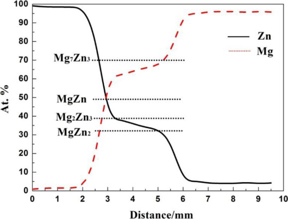
EDS linescan results of line indicated in Fig. 4d
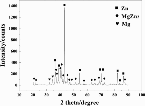
XRD patterns obtained from fracture surfaces of Zn side
Based on the above analysis, the formation process of the joint can be described as follows. When static pressure and tangential force are applied by the rotating sonotrode, the faying surface comes into close contact. The local surface oxide layer between contacting asperities begins to break down and metallic adhesion takes place. The initial adhesion spots grow to form microbonds under the action of material plastic deformation. The preceding GTAW can preheat the sheet metal to enhance the ultrasonic weldability. The area of real contact increased with the GTAW current increasing. Owing to the formation of the microbonds and sufficient plastic deformation, interdiffusion takes place in the vicinity of the microbonds areas. Therefore, the Al–Zn eutectic structure forms at the Al–Zn interface, while the MgZn2 layer was present at the Mg–Zn interface. With the GTAW current increasing, the thickness of Al–Zn eutectic structure and MgZn2 layer increases. The addition of Zn interlayer can restrain the extreme reaction between Al and Mg atoms. The formation of hard and brittle Mg–Al IMCs was suppressed. Therefore, the mechanical properties of the joints were improved.
Weld temperatures
Figure 8 shows the relationship between peak weld temperature and GTAW current, determined at the centre of the weld as described in the ‘Experimental’ section. The peak temperature without GTAW hybrid is 245°C. It could be seen that the higher GTAW current resulted in a higher temperature at the centre of the weld. The maximum temperatures recorded by the thermocouples rose from 272°C for GTAW current of 15 A to 371°C for GTAW current of 25 A to 470°C at the maximum GTAW current of 35 A. The peak temperature was obviously sufficient for mutual diffusion of Al/Zn interface and Zn/Mg interface. 24 Even constitutional liquation occurred because of the lower melting point of Zn (420°C).
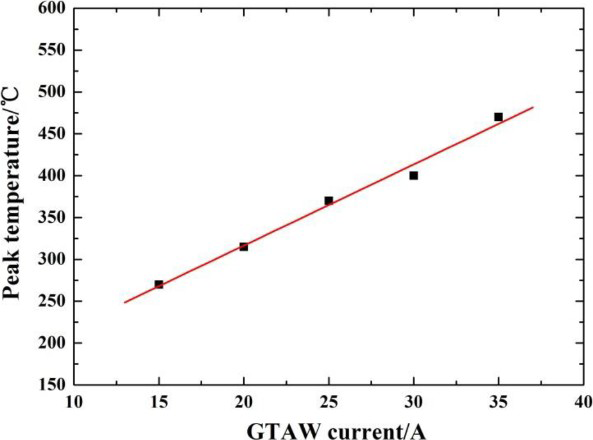
Peak temperature as function of GTAW current
Vickers microhardness
The microhardness profile diagonally across the welded joint for GTAW current of 20, 25 and 30 A was shown in Fig. 9a. It could be indicated that the hardness of the joints increased with increasing GTAW current, where the trend was more obvious on the region of welded Al and Mg side. The hardness of the Zn interlayer was ∼50–60 HV, the mean of measurements at three different locations along the length of the Zn interlayer. The hardness in the vicinity of the weld near Al side and Mg side was 65–75 HV and 63–74 HV, and then jumped to 96–117 HV and 94–135 HV respectively. That was obviously due to the strain hardening in the vicinity of the weld. The Al/Zn and Mg/Zn interface exhibited maximum hardness values of 125–135 HV and 130–135 HV due to the absence of Al–Zn eutectic structure and Mg–Zn IMCs. Figure 9b shows the microhardness profile of the joint with and without Zn interlayer at GTAW current of 30 A. It could be seen that Zn interlayer addition could lead to a significant decrease in the hardness of the interface. The hardness of Al–Mg IMCs (230–260 HV) was much higher compared to the Al–Zn eutectic structure (125–135 HV) and Mg–Zn IMCs (130–135 HV). Therefore, the mechanical properties of the joints with Zn interlayer were improved.
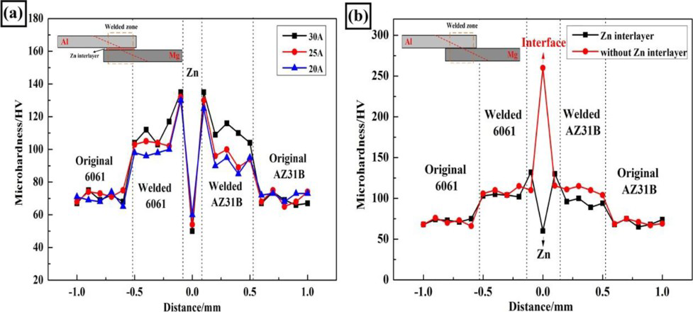
Microhardness profile obtained across cross-section of following samples: a at different GTAW currents; b GTAW current of 30 A
Lap shear tensile strength
The lap shear strength of dissimilar Al–Mg welds with and without Zn interlayer as a function of GTAW current was shown in Fig. 10. It could be concluded that the lap shear strength of the joints indicated improvements with the addition of Zn interlayer. The maximum lap shear strength of the joint for GTAW current of 30 A was ∼16.25 MPa, which was ∼30 increase over the sample without Zn interlayer (∼12.5 MPa). The increase in the lap shear strength was attributed to the formation of Zn based solution and Mg–Zn IMCs, instead of the brittle Mg–Al IMCs. In addition, it also could be seen that similar increasing trend was observed for both types of welds with and without Zn interlayer. The lap shear strength of the joints increased with increasing GTAW current and reached the maximum at GTAW current of 30 A and then decreased sharply for GTAW current of 35 A. This was the consequence of the dynamic balance between the increasing mutual diffusion joining at higher GTAW current and the deteriorating effect of the brittle IMC layers.24–27 At lower GTAW currents, the temperature was not yet risen sufficiently to form a sound joint. However, the temperature could reach 470°C at higher GTAW current of 35 A, which was higher than the melting point of Zn. Constitutional Zn liquation occurred and then squeezed out under the action of ultrasonic vibration. Therefore, the lap shear strength decreased sharply to ∼3.75 MPa.
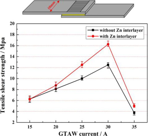
Comparison of lap shear strength with and without Zn interlayer as function of GTAW current
Failure behaviour
Typical macroscopic photo of the failed lap shear tensile samples was shown in Fig. 11a. All the joint failure occurred by the interface mode rather than the pullout mode at the Mg/Zn interface. It could be concluded that the Mg/Zn interface was the weakest zone of the joint. This was well in agreement with the previous microstructure observation in Figs. 3 and 4. The microstructure of Al/Zn interface was mainly consisted of Zn based solution and Al–Zn eutectic structure, while the Mg–Zn IMCs (such as MgZn2) were found at Mg/Zn interface. Therefore, the microcrack occurred first at the Mg–Zn IMCs and then propagated along the Mg/Zn interface during the lap tensile test.
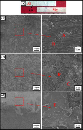
Typical fractured welded joints: a macroscopic images of failed lap shear tensile samples; SEM images of fracture surface on Mg side at GTAW of b 20 A, c 25 A and d 30 A, and EDS box analysis in magnified fracture surface area
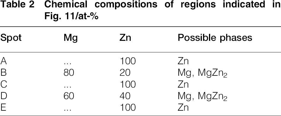
Figure 11b–d shows the SEM images of fracture surface on the Mg side of the lap shear tensile failed samples at GTAW current of 20, 25 and 30 A. It could be concluded that all the fracture patterns exhibited entirely brittle fracture mode with cleavage facet feature surface. In addition, there were two kinds of regions present on the fracture surface: a bright white region and a dark grey substrate. Quantitative analysis of the chemical composition (spots A–E) by EDS was listed in Table 2. It could be seen that the bright white region (spots A, C and E) consisted of 100 Zn, which suggested that this region mainly contained remains or debris Zn interlayer. In addition, the dark grey substrates (spots B and D) were 80 Mg, 20 Zn and 60 Mg, 40 Zn respectively, which indicated that this region mainly consisted of Mg based solution and MgZn2 phases. This was in good agreement with the XRD results. In addition, the remains or debris Zn interlayer region expanded and spread across the matching fracture surface with the GTAW current increasing. The EDS results also showed that the interdiffusion of Zn and Mg atom was enhanced, because 40 Zn atom in spot D was higher than 20 Zn atom in spot B.
Chemical compositions of regions indicated in Fig. 11/at-
Weld defect analysis
As described above, a good ultrasonic weld could be obtained, if proper parameter of GTAW current was selected. When the GTAW current was < 15 A, a continuous and substantial gap or unbonded zone at the Mg/Zn interface could be observed in Fig. 12. That was because the temperature was not yet risen sufficiently for the chemical reaction of Mg and Zn atoms. 28 It was also demonstrated that the Mg/Zn interface was the weakest zone. However, as the GTAW current exceeded 35 A, the temperature was higher than the melting point of Zn. Therefore, constitutional Zn liquation was formed at the interface and then squeezed out under the action of ultrasonic vibration as shown in Fig. 12b.
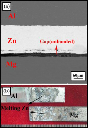
Weld defects: a unbonded weld; b melting Zn
Conclusions
GTAW assisted hybrid ultrasonic seam welding of 1 mm thickness MgAZ31B and Al6061 alloy sheets was successfully completed using Zn interlayer. The maximum lap strength of the joint with Zn interlayer was ∼16.25 MPa at the GTAW current of 30 A, which was ∼30 increase over the joint without Zn interlayer. This improvement was attributed to the formation of Al–Zn eutectic structure, Zn based solution and MgZn2 phases instead of the brittle Al–Mg IMCs at the interface. The joint consisted of two distinct interface zones: Al/Zn interface and Mg/Zn interface. The Mg/Zn interface was the weakest zone of the joint. All the joint failures occurred by the interface mode rather than the pullout mode at the Mg/Zn interface. In addition, the fracture patterns exhibited entirely brittle fracture mode with cleavage facet feature surface. The remains or debris Zn interlayer region expanded and spread across the matching fracture surface with the GTAW current increasing.