
Abstract
The iron based hardfacing alloys were produced using slag free self-shielded flux cored wires with varying niobium contents. The results show that NbC acted as the nucleus of primary M7(C, B)3 (M = Cr, Fe mainly) carbides and decreased the amount of M7(C,B)3 carbides when niobium was added into the alloys. When 18 wt-%Fe–Nb (60 wt-%Nb) was added, the microstructure of hardfacing alloy transformed from hypereutectic structure to a eutectic one due to the formation of NbC, which consumed a mass of carbon. The microstructure changed into a hypoeutectic structure when the Fe–Nb content was up to 24 wt-%. With the increase in Fe–Nb content, the main abrasive wear mechanism changed from microcracking to microcutting and microploughing due to the formation of NbC and the reduction of primary M7(C, B)3 carbides. The wear loss of the alloy with 18 wt-%Fe–Nb addition was the smallest among all the alloys.
Introduction
Wear, as one of the most important materials failure phenomena in mineral industries, leads to enormous costs from materials and energy losses. 1 The hypereutectic iron based alloys are considered as the preferred hardfacing alloy for repairing the damaged components that are required to endure severe abrasive mainly owing to enormous quantities of primary M7C3 carbides within their microstructures. 2
In the wear process, the coarse M7C3 carbide plays an important role in the improvement of the wear resistance of the alloy through the provision of a barrier against microcutting and microploughing. 3 As the amount of M7C3 increases, the wear resistance of the hardfacing alloy is improved. 4 The morphology of M7C3 carbides also plays an important role in wear resistance. 5 In fact, the blade and rod-like M7C3 carbide morphologies correspond to the same hexagonal rod-like structures, but are oriented in different directions relative to the sectioning plane. 6 However, there are common pitfalls to be encountered when the iron based hardfacing alloys are exposed to heavy external impacts. Since M7C3 carbide is surrounded with metastable matrix of austenite, which is relatively soft compared to M7C3 carbide (∼1600 HV),7–9 the continuity between the carbides is deteriorated; thus, cracks spread through the M7C3 carbide or along the interface between M7C3 carbide and matrix, leading to the early cracking during the wear process. Additionally, Babout et al. 10 have defined the hard phase fracture by continuous failure at the interface between hard phase and matrix due to plastic deformation of the matrix. But if the matrix is enhanced, the coarse M7C3 carbides can avoid spalling and delamination. 2
Therefore, many researchers have reported that the addition of strong carbide forming elements such as W, V, Ti and Nb to obtain MC type carbides, which are harder and finer than M7C3 carbides. These efforts improve the wear resistance of iron based hardfacing alloys to a degree.9, 11–13 To date, the arc welding processes are frequently employed to deposit iron based alloys including manual metal arc welding, self-shielded flux cored arc welding and submerged arc welding. Among these processes, automatic self-shielded flux cored arc welding is commonly used because it gives high deposition rates without the use of external flux.14, 15 However, few studies have obtained enough MC type carbides for the replacement of M7C3 carbides in this welding technology, mainly due to the manufacturing difficulties associated with its flux cored wire powder fill factor. It is claimed that only ∼50 wt-% of the final alloy powders can be varied with the filling. 16 The other parts of additives usually consist of mineral powders such as rutile, marble and fluorite; these powders form a slag during the welding process to protect molten metal from pollution and oxidation. The mineral powders occupy more space because of its lesser density compared to metal powders within the core. Thus, the addition of ferroalloys, such as ferroniobium, is restricted.
According to the demands of abundant metal powders additive into the core to form abrasion resistance deposit during the welding process, we have developed a new type of iron based slag free self-shielded flux cored wire.7, 9, 17 In the present study, the effects of niobium on the microstructure and abrasion resistance of iron based slag free self-shielded flux cored wire hardfacing alloys were discussed.
Experimental
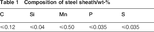
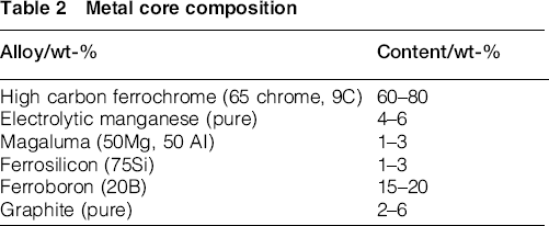
The self-shielded flux cored wire with a diameter of 2.8 mm included a steel sheath with a core. The chemical composition of steel sheath is shown in Table 1, and the composition of powdery metal core filled within steel sheath (filling rate, 55 wt-%) is shown in Table 2. In order to investigate the effects of niobium additive on microstructure and wear performance of Fe based hardfacing alloys, the mass fraction of ferroniobium (Fe–Nb, containing 60 wt-%Nb) added into core wire was 0, 6, 12, 18 and 24 wt-%.
Composition of steel sheath/wt-%
Metal core composition
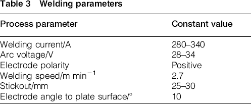
Mild steel with the dimensions of 150 × 75 × 50 mm was selected as the substrate material. In order to obtain the homogeneous specimen, hardfacing alloys with five layers were prepared by means of metal cored self-shielded arc welding without pre- and post-heat. The welding parameters are presented in Table 3.
Welding parameters
The samples were cleaned in an ultrasonic cleaning machine for 5 min before and after the test. The macrohardness was taken on the top surface of the hardfacing alloys by an HR-150A Rockwell hardness tester. The chemical compositions of the hardfacing alloys were analysed by a SPECTRO MAXx LAB optical emission spectrograph. The etching agent was composed of 15 mL of 38% hydrochloric acid solution, 50 mL H2O, 3 mL of 68% nitric acid solution and 3 g ferric chloride. The microstructures were observed by optical microstructure, scanning electron microscope (SEM). Twenty randomly selected regions with areas of 16 × 16 mm were used for image analysis to determine the carbide volume fraction (CVF) in microstructures of hardfacing alloys with varying Fe–Nb contents.
Abrasion testing was carried out using a MLS-225 wet sand rubber wheel test machine. The specimen size is 5726 × 6 mm. After the specimen was cut from the hardfacing alloys, it was ground using a no. 600 SiC paper to remove the sharp edges and then polished. Wet sand was made of 1 kg water and 1.5 kg abrasion SiO2 round sand (60 mesh). The rubber wheel with a diameter of 178 mm was rotated with a speed of 240 rev min− 1 for 1000 cycles under an applied load of 10 kg. The hardness of the rubber wheel was 60 HA (Shore hardness). An electronic balance (accuracy, 0.1 mg) was used to weigh the specimens before and after abrading. Three testing specimens were made from each sample and were tested separately. An average of the three numbers was calculated and recorded. The wear tracks were observed by SEM.
Results and discussion
Effect of Nb on microstructure of hardfacing alloy
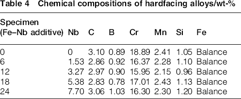
Table 4 shows the chemical compositions of the hardfacing alloys. With the increase in niobium additive in the wire, the niobium content increases in the hardfacing alloy. Figure 1 shows the X-ray diffraction pattern of the hardfacing alloys. The phase in the hardfacing alloy without niobium addition was mainly composed of (Cr, Fe)7(C, B)3, Fe3(C, B), martensite and residual austenite. The figure also shows the presence of NbC in the hardfacing alloy with niobium addition (e.g. the alloy containing 18 wt-%Fe–Nb).
Chemical compositions of hardfacing alloys/wt-%
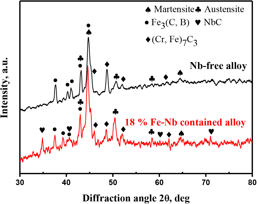
X-ray diffraction pattern of hardfacing alloys with various Fe–Nb contents
The surface microstructures of hardfacing alloys with different niobium additions and CVFs are summarised in Fig. 2. As shown in Fig. 2a, the Nb free hardfacing alloy displayed a typical hypereutectic microstructure, which consisted of primary hexagonal shaped M7(C, B)3 and eutectic colonies of M3(C, B) plus martensite and residual austenite as determined by X-ray diffraction analysis. With increasing the amount of Fe–Nb additive (Fig. 2b–e), the primary M7(C, B)3 carbides gradually refined and became more uniform. Moreover, the white irregular particles were formed and increased in the niobium containing hardfacing alloys. An interesting feature in Fig. 2d is that the microstructure was equiaxed eutectic without any primary M7(C, B)3 carbides in the alloy with the addition of 18 wt-%Fe–Nb. When the Fe–Nb amount increased up to 24 wt-%, the structure changed into a hypoeutectic one with primary dendritic austenite (Fig. 2e). Figure 2f displays the change of average carbide volume fraction. The NbC carbide volume fraction increased in proportion to the niobium additive, whereas the primary carbide volume fraction decreased. The primary austenite appeared, and the average volume fraction was 8.1 % in the alloy with 24%Fe–Nb additive.

Microstructures of hardfacing alloys with different niobium additives of a 0 wt-%Fe–Nb, b 6 wt-%Fe–Nb, c 12 wt-%Fe–Nb, d 18 wt-%Fe–Nb and e 24 wt-%Fe–Nb and f carbide volume fraction (CVF) in microstructures of hardfacing alloys with various Fe–Nb contents
Figure 3 shows the distribution of niobium, chromium, manganese and iron in Nb containing alloy examined by energy dispersive spectroscopy mapping analysis. It was found that the white irregular phases were rich in niobium, which identified that those phases were NbC carbides. In addition, chromium was detected in another type of precipitations with grey colour, while iron was detected both in the matrix and precipitations. It was identified that the grey precipitations were Cr rich carbides.

Scanning electron microscopy shows a microstructure of Nb containing hardfacing alloy and b–e corresponding X-ray maps of Nb, Cr, Mn and Fe
The effects of different niobium additions on the microstructures of hardfacing alloys are shown in Fig. 4. In Fig. 4a, the formation of eutectic colonies (M3(C, B) plus austenite) surrounding primary M7(C, B)3 carbides were present in the Nb free hardfacing alloy. In the solidification process, the primary M7(C, B)3 carbides were separated first from the molten. The residual molten became less in chromium, carbon and boron, and the eutectic M3(C, B) carbides and austenite simultaneously formed around the grain boundary of primary M7(C, B)3. Therefore, the sample without niobium had a typical hypereutectic structure showing primary M7(C, B)3 in the eutectic colonies of austenite plus M3(C, B). When the Fe–Nb content was 6 wt-%, it was noted that pipe shaped NbC carbides were formed in the microstructure, the M7(C, B)3 carbides were refined, and more eutectic colonies were precipitated (Fig. 4b). By increasing the Fe–Nb addition to 12 wt-%, the NbC carbides became irregular, and the microstructure was refined compared to that of hardfacing alloy with 6 wt-%Fe–Nb (Fig. 4c). When the content of Fe–Nb reached to 18 wt-%, the primary M7(C, B)3 carbides disappeared, which indicates a near eutectic structure (Fig. 4d ). As the amount of Nb–Fe increased up to 24 wt-%, the distribution of NbC carbides was relatively dense compared to other hardfacing alloys, and the microstructure changed from a eutectic structure to a hypoeutectic one (Fig. 4e). The changes in microstructures indicated that niobium addition shifted the eutectic point to the right. Similar effect was found in Ti doped hardfacing alloy owing to the formation of TiC which consumed carbon. 17
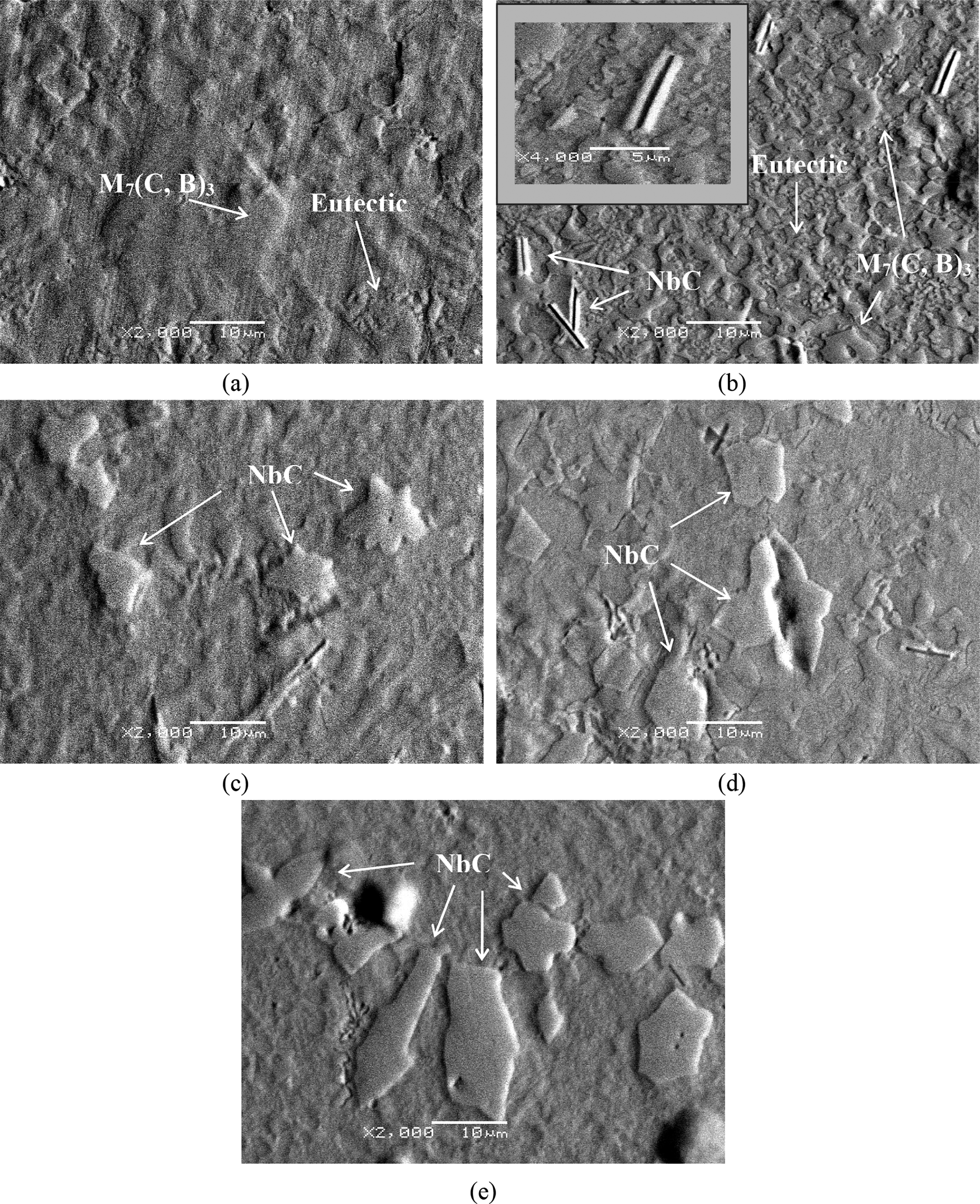
a 0 wt-%Fe–Nb; b 6 wt-%Fe–Nb; c 12 wt-%Fe–Nb; d 18 wt-%Fe–Nb; e 24 wt-%Fe–Nb
Niobium is a strong carbide forming element and easily forms niobium carbides with carbon. 18 In hypereutectic Fe–Cr–C–B hardfacing alloy, NbC particles are formed before M7C3 carbides when niobium is added into the alloys. 19 The rapid cooling after welding offered a favourable condition for the nucleus formation of M7(C, B)3 carbide. Thus, the M7(C, B)3 carbide could be nucleated on the NbC surface, leading to the refinement of primary M7(C, B)3 carbide. Furthermore, the formation of NbC depleted carbon in the molten, thus reducing the volume fraction and size of the primary M7(C, B)3 carbides. The carbon left in the molten after the formation of NbC determined the final type of microstructure. Therefore, the microstructure of hardfacing alloy transformed from hypereutectic structure to a eutectic structure when the content of Fe–Nb was 18 wt-% and changed into a hypoeutectic one when the Fe–Nb content was up to 24 wt-%.
Effect of Nb on hardness and wear behaviour of hardfacing alloy
Figure 5 shows the change of hardness and wear loss as the amount of niobium increased in the hardfacing alloy. The hardness of hardfacing alloy was 59 HRC with no Fe–Nb addition and increased to 64 HRC with 18 wt-%Fe–Nb addition. However, the alloy hardness was slightly decreased to 63 HRC with 24 wt-%Fe–Nb addition. On the other hand, the wear loss of hardfacing alloy was continuously decreased with increasing the content of Fe–Nb to 18 wt-%, and then changed a little. In the iron based alloy studied by Lampke et al., 20 the matrix structure, the fraction and the size of carbides affected its macrohardness. The NbC has an average hardness of 2550 HV, which was higher than that of the primary M7(C, B)3 carbides (1600 HV).21, 22 Thus, the higher volume fraction of hard NbC (Fig. 3f ) contributed to higher hardness, although the amount of M7(C, B)3 carbides was decreased. Additionally, the finer microstructure obtained by niobium addition increased hardness according to the Hall–Petch relationship. Furthermore, the Nb content reduced the volume fraction of M7(C, B)3 carbides due to the depletion of carbon that was consumed by Nb to form niobium carbides and increased the amount of chromium within the matrix, leading to a solid solution strengthening of matrix. Consequently, the addition of Nb was conducive to a combination of reinforced carbides and a tough matrix, thus leading to the high hardness of iron based hardfacing alloy. When the content of Fe–Nb increased from 18 to 24 wt-%, the hardness of hardfacing alloy was decreased with respect to the formation of primary austenite in the hypoeutectic microstructure.
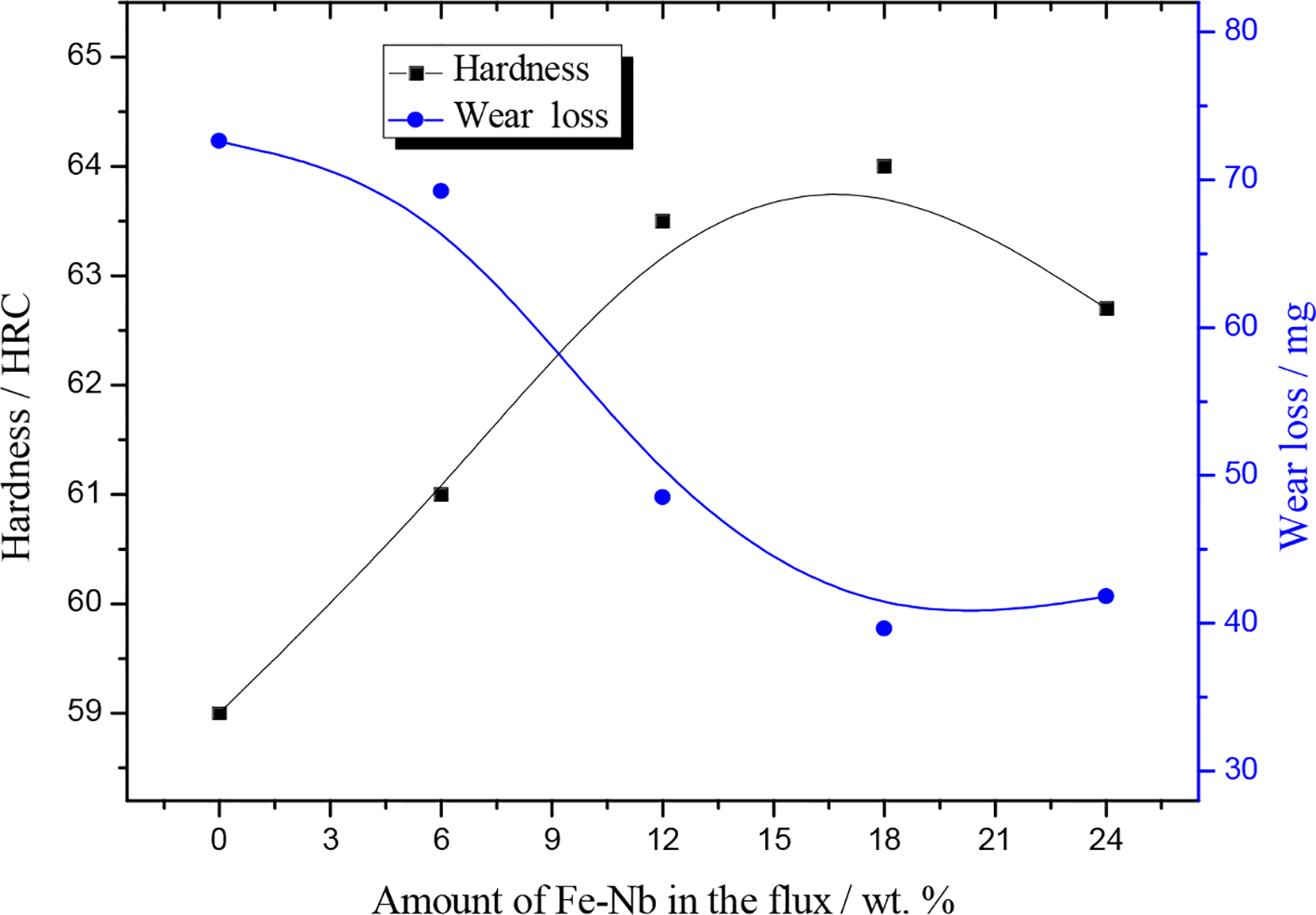
Effect of niobium content on hardness and wear loss of hardfacing alloys
Figure 6 shows SEM images of the wear surface and cross-section of wear surface of the niobium free alloys. According to Chang et al. and Zum Gahr,2, 23 the main abrasive wear mechanisms are microcutting, microcracking and microploughing. Microcracking of the primary M7(C, B)3 carbides in the niobium free alloy appeared to the dominant mechanism of material removal according to the numerous craters and cracks observed on the wear surface (Fig. 6a). Since brittle primary chromium carbides formed pre-existing microcracks or voids in the carbide during the welding solidification process, 24 the formation of crater was owing to abrasive SiO2 particles continuously attacking the M7(C, B)3 carbides causing these carbides fracture and pullout (Fig. 6b). It was documented in the literature 25 that high stress concentration presented in the coarse and brittle carbides greatly influenced the release of strain energy, crack nucleation and propagation during the abrading process. Moreover, the strain energy was developed much faster at these regions, making them more vulnerable to form microcracks. The microcracks were increased with the increasing the ratio of hardness and fracture toughness, thus increasing the wear rate. 23
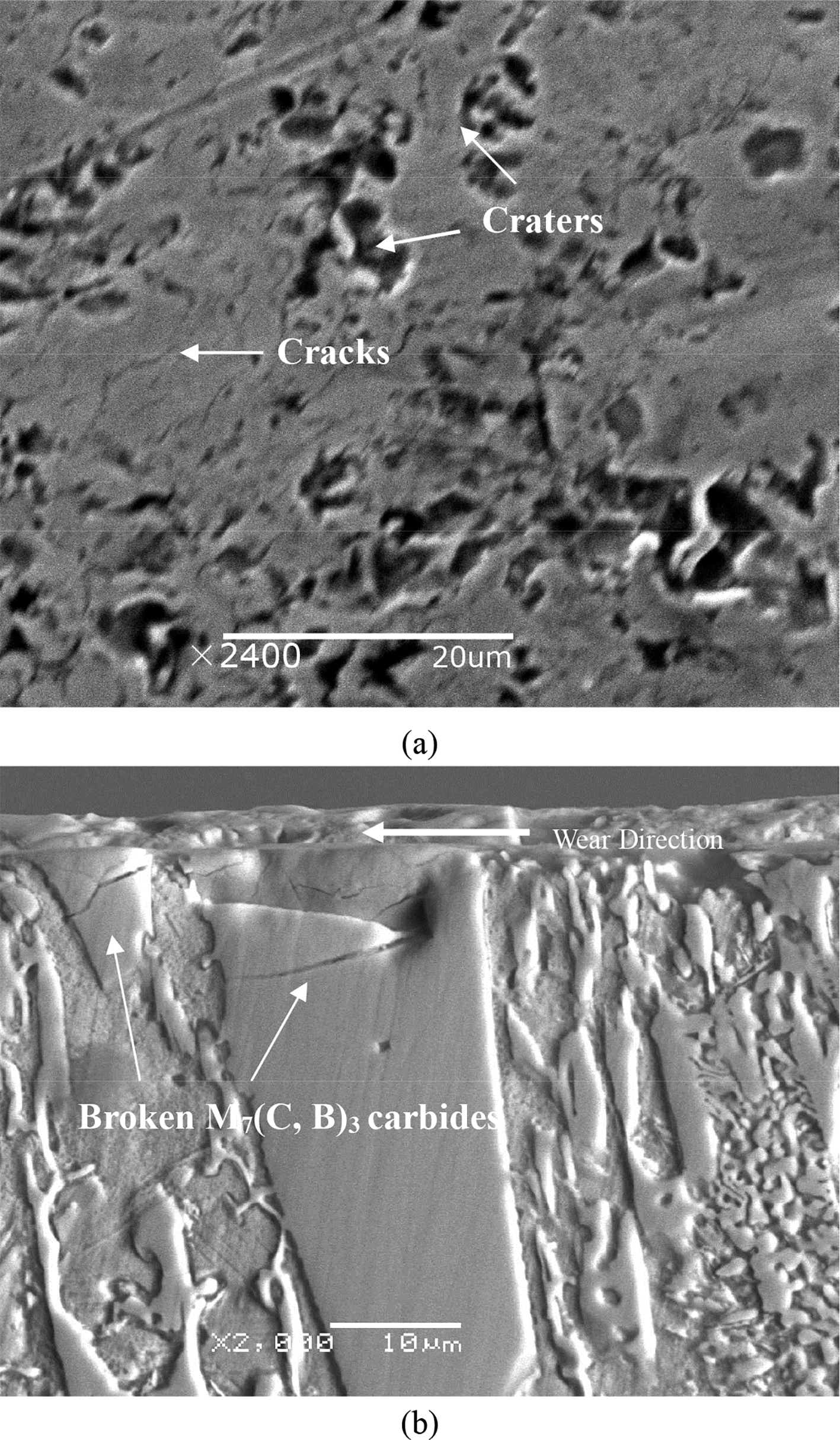
Images (SEM) of a wear surface and b cross-section of wear surface of niobium free alloys
Figure 7 shows SEM images of the wear surface and cross-section of wear surface of the niobium containing (Fe–Nb, 18 wt-%) alloys. Microcutting and microploughing are evidenced by gross plastic deformation in Fig.7a. The absence of cracks in the niobium containing alloys (Fig. 7b) owing to maintaining the NbC carbides firmly incorporated in the matrix during abrasion resulted in an improved wear resistance in comparison with niobium free alloy. It is seen in Fig. 7c that NbC carbides resisted wear effectively, and no cracks existed in this hard phase. NbC phases were introduced into the matrix of the niobium containing alloys during the solidification process of the weld pool. The Nb containing hardfacing alloys had the microstructure characteristics that hard NbC uniformly distributed in the fine and strong M3(C, B) plus austenite eutectics matrix, which ensured the excellent wear resistance of the hardfacing alloy. Similar morphologies were observed in high chromium nickel based alloy. 26 The NbC carbides with high hardness played the dominating role in wear resistance. With the protection of the NbC carbides, the eutectics matrix can avert severe selective wear. When the content of Fe–Nb exceeded 18 wt-%, the wear resistance no longer improved owing to the decrease in the hardness of the hardfacing alloy. Therefore, the wear loss of the sample changing with the niobium content is mainly attributed to two aspects. One was a supporting effect of the NbC carbides on the matrix and the refined microstructure to protect the hardfacing layer from wearing. The second was a protecting effect of the enhanced matrix to carbides.
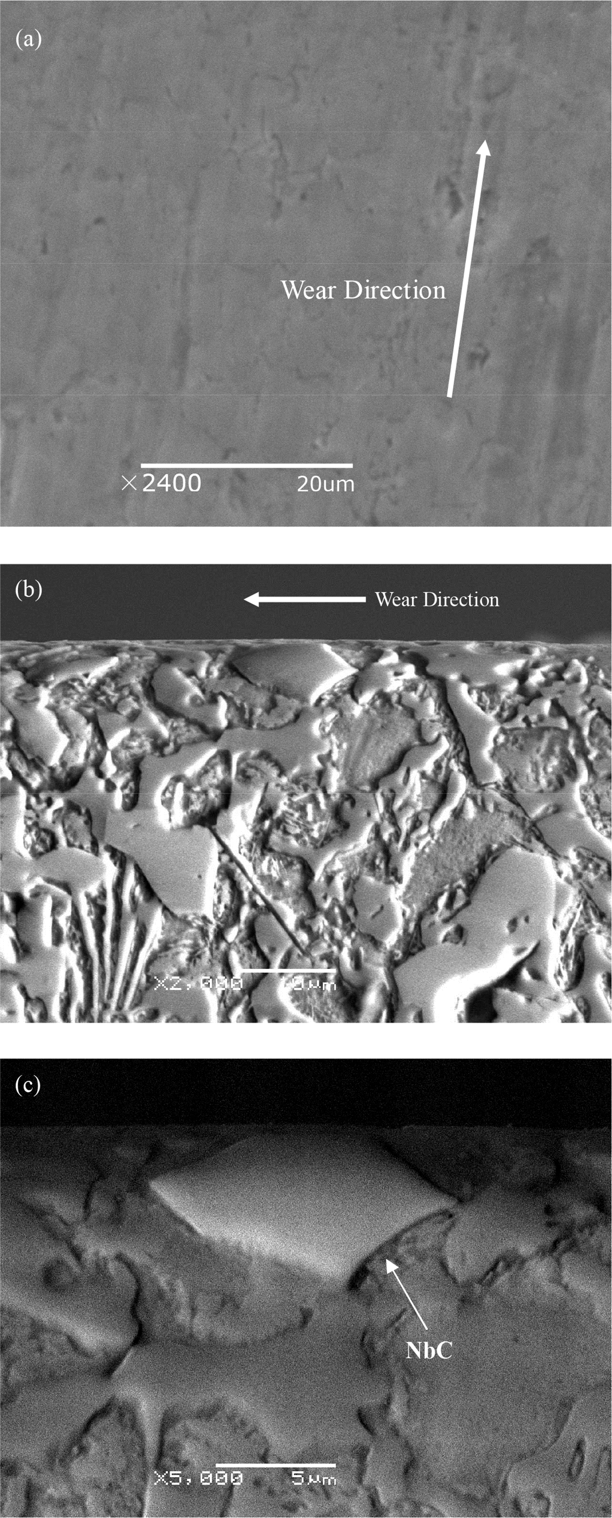
Images (SEM) of a wear surface and b cross-section of worn surface of niobium containing (Fe–Nb, 18 wt-%) alloys and c local magnification for Fig. 9b
Figure 8 illustrates schematically the wear behaviour of Fe–Cr–B–C hardfacing alloy. The cavities and microcracks were formed in the coarse and brittle M7(C, B)3 chromium carbides, as shown in Fig. 8a. Since the hardness of rubber wheel is lower than that of SiO2 abrasive particles, the sharp corners of SiO2 abrasive particles were impacted in the rubber wheel. The surface of the hardfacing alloy were cut by these SiO2 abrasive particles, which are like ‘turning tools’ fastened to the rubber wheel. The softer matrix was first cut by the ‘turning tools’, resulting in the exposure of the M7(C, B)3 carbides, as shown in Fig. 8b. The microcracks took place and expanded in the exposed M7(C, B)3 carbides owing to more impact forces as shown in Fig. 8c. Finally, the exposed M7(C, B)3 carbides scaled off the surface owing to the joined cracks, as shown in Fig. 8d. Therefore, the predominant wear mechanism was microcracking. Figure 8e–g illustrates schematically the wear behaviour of NbC reinforced Fe–Cr–B–C hardfacing alloy. The dispersive MC carbides reinforced matrix and the bonding between matrix and the MC carbides. Thus, the NbC reinforced Fe–Cr–B–C hardfacing alloy retained fair matching of high strength and high toughness. In the wear process, the hardfacing alloy was subjected to the comprehensive action of tangential and normal force, leading to the plastic deformation of the matrix. The groove was found in the outstanding toughness matrix. Therefore, the NbC reinforced Fe–Cr–B–C hardfacing alloy was improved.
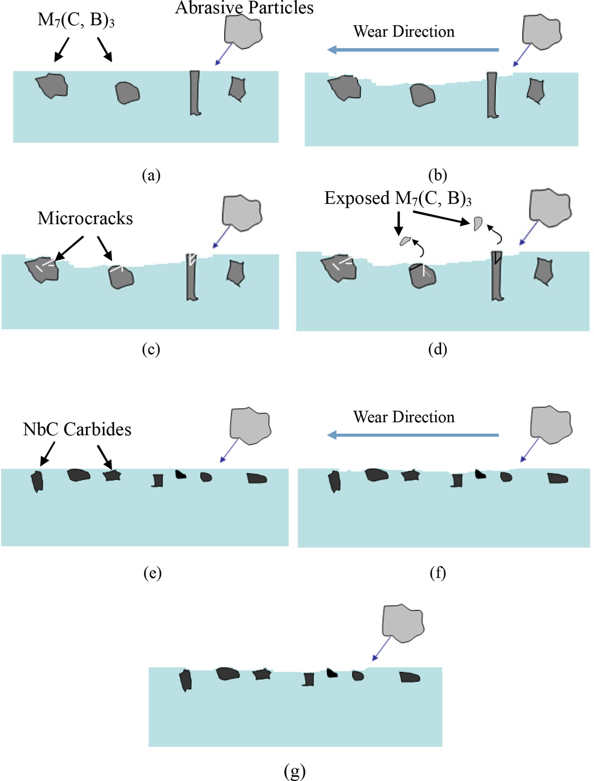
Schematic diagrams of wear mechanism of a–d Fe–Cr–B–C hardfacing alloy at a first stage, b second stage, c third stage and d fourth stage and e–g NbC reinforced Fe–Cr–B–C hardfacing alloy at e first stage, f second stage and g third stage
Conclusions
The NbC carbide reinforced iron based hardfacing alloy was produced using slag free self-shielded flux cored wire with the addition of Fe–Nb. NbC acted as the nucleus of the primary M7(C, B)3 carbides and decreased the amount of M7(C,B)3 carbides when niobium element was added into the alloys. When 18 wt-%Fe–Nb was added, the microstructure of hardfacing alloy transformed from hypereutectic structure to a eutectic one due to the formation of NbC, which consumed a mass of carbon. Moreover, the microstructure changed into a hypoeutectic structure when the Fe–Nb content was up to 24 wt-%. The addition of niobium to iron based hardfacing alloy improved the wear resistance of the alloy owing to the refined microstructure and higher hardness. With the increase in Fe–Nb content, the main abrasive wear mechanism changed from microcracking to microcutting and microploughing due to the formation of NbC and the reduction of primary M7(C, B)3 carbides. The wear loss of the hardfacing alloy with 18 wt-%Fe–Nb addition was the smallest among all the alloys.
Acknowledgements
This work was supported by funding of the National Natural Science Foundation of China (grant no. 51405208), Open Research Fund of Provincial Key Laboratory of Advanced Welding Technology of Jiangsu University of Science and Technology (grant no. JSAWT-14-03), Foundation for Scientists of Jiangsu University of Science and Technology (grant no. 635061312) and a Project Funded by the Priority Academic Program Development of Jiangsu Higher Education Institutions.