
Abstract
The presence of chloride ions exceeding its critical concentration in its surrounding is one of the major causes for reinforcing steel corrosion, and subsequently, reduction in the strength of the structure occurs. A common method of preventing such deterioration is to prevent chlorides from penetrating the structure to the level of the reinforcing steel bar by organic corrosion inhibitors. The electrochemical behaviour of mild steel in seawater with or without 4[{(4,6-diamino-1,3,5-triazine-2-yl)imino}methyl]-2,5-cyclohexadiene-1-one, a new triazine inhibitor, is identified and synthesised by Insilco techniques in parts I and II of our previous study. Part III presents the evaluation of the new inhibitor in reinforced steel concrete specimens by current induced accelerated corrosion method and also its performance to prevent chloride penetration in concrete structures. Tests were conducted to Indian standards, ASTM standards and Council of Scientific and Industrial Research guidelines to control rebar corrosion. Results showed that the inhibitor efficiency is up to 85%, and also the rate of chloride penetration into the concrete specimens was decreased when the new inhibitor is used as admixture. In addition, the relationship between the molecular structure of these compounds and their inhibition efficiency has been investigated by ab initio quantum chemical calculations using Cerius 2 software program.
Keywords
Introduction
Corrosion is the destructive attack of a material by reaction with its environment. The serious consequences of the corrosion process have become a problem of worldwide significance. In addition to our everyday encounters with this form of degradation, corrosion causes plant shutdowns, waste of valuable resources, loss or contamination of product, reduction in efficiency, costly maintenance and expensive overdesign. Corrosion control is achieved by recognising and understanding corrosion mechanisms and using corrosion resistant materials and designs. The cost attributed to corrosion damages of all kinds has been estimated to be of the order of 3-5% of the gross national product of industrialised countries.
Corrosion of the reinforcing steel due to chloride ingress and exceeding its critical concentration is one of the most common environmental attacks that lead to the deterioration of concrete structures. It is well known that the steel embedded in concrete is protected from corrosion by the alkalinity of the cement matrix, which aids to form a passive film on the steel surface.1 If chloride ions are present in the reinforcement zone, then protection may be breached even at higher pH values, the precise value depending on the chloride concentration of this zone. The critical value for corrosion to occur is related to the chloride hydroxyl ion concentration ratio. Hausman has shown that when this ratio is higher than 0·6, corrosion of the rebar is possible.2 The higher the chloride ion concentration, the greater the probability of corrosion. To predict the probability of corrosion, it is necessary to know the chloride concentration in the concrete next to the reinforcement and the position of the concentration front relative to it.3 The volume of rust products is about four to six times larger than that of iron. This volume increase induces internal tensile stresses in the cover concrete, and when these stresses exceed the tensile strength of the concrete, the concrete cover is damaged by cracking, delamination and spalling. In addition to loss of concrete cover, a reinforced concrete member may suffer structural damage due to loss of bond between steel and concrete and loss of rebar cross-sectional area.4 Win et al. determined the penetration profile of chloride in cracked reinforced concrete and found that the reinforced concrete specimens having cracks showed rapid penetration of Cl− ion, which finally reached the steel. Penetration along the steel also occurred.5 Martin-Perez et al.6 proposed an algorithm based on modified Fick's second law for the numerical modelling of transport of chlorides, moisture, oxygen and heat convection through concrete. Montemor et al.7 presented an overview on the state of the art of the most important aspects of the corrosion process initiated by chlorides, its development and monitoring techniques.
Various methods are being used to extend the life of reinforced concrete structures, which include coatings on the concrete surface, coatings on the reinforcement, cathodic protection, electrochemical chloride removal and corrosion inhibitors. Of these methods, the use of corrosion inhibitors is found to be one of the effective methods to control rebar corrosion.8 – 12 The published part I of the research work by us13 is focused on designing a new corrosion inhibitor by Insilco techniques and its synthesis in the wet lab. Part II of the research work submission being processed14 is focused on the preliminary investigation of corrosion studies with 4[{(4,6-diamino-1,3,5-triazine-2-yl)imino}methyl]-2,5-cyclohexadiene-1-one, a new corrosion inhibitor for mild steel in concrete atmosphere surrounded by saline atmosphere. The present paper, part III of the research work, focuses on the evaluation of the triazine inhibitor in reinforced steel concrete specimens by current induced accelerated corrosion method developed in Japan and also its performance to prevent chloride penetration in concrete structures.
Experimental
Simulated pore solution testing is a screening process that evaluates the performance of chemicals for inhibiting steel reinforcement corrosion in a high alkaline environment, which is usually simulated by saturated calcium hydroxide solution. The screening process of the inhibitor (which is under review) was our previous research work, i.e. part II,14 and we came to conclude that the synthesised triazine derivative controlled both cathodic and anodic reactions, thus acting as a mixed type inhibitor, and at 5% inhibitor concentration, i.e. the optimum concentration, the corrosion rate is very low compared to that of other concentrations. Hence, we have taken 5% as the optimum concentration of the inhibitor in our further investigation process.
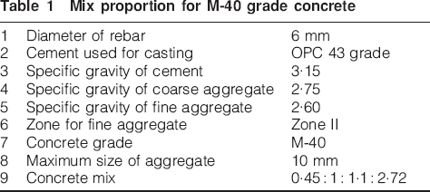
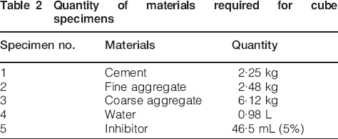
The surfaces of mild steel specimens used for this study were polished with a series of emery paper up to 1200 grade, washed thoroughly with distilled water, degreased and dried with acetone. The aggressive saturated calcium hydroxide, i.e. concrete atmosphere, was prepared with distilled water. Cubes were cast using M-40 grade concrete. In total, six cubes and five cylinders were caste according to the design size of 100 mm and cylinder specimens of 100 mm diameter and 50 mm height. Among them, three cubes and two cylinders are caste without inhibitor, and three cubes and cylinders each are caste with synthesised inhibitor. The schematic diagram of cube specimens is shown in Fig. 1. The molecular structure of the newly synthesised inhibitor molecule is shown in Fig. 2. The mix design quantities of the materials required for the casting of the cube are shown in Table 1, and the quantity of materials required for cubes and cylinders is mentioned in Table 2 Tables 2 and 3.
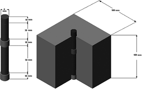
Schematic diagram of reinforced steel in concrete
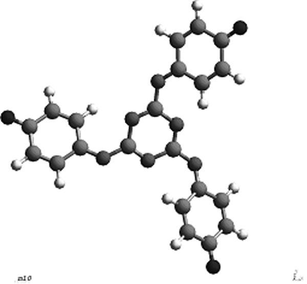
Molecular structure of newly synthesised inhibitor molecule
Mix proportion for M-40 grade concrete
Quantity of materials required for cube specimens
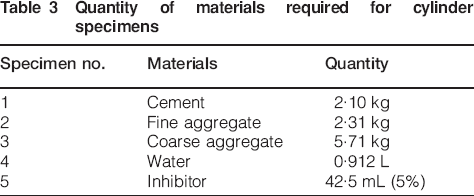
Quantity of materials required for cylinder specimens
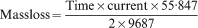
A current induced accelerated corrosion method developed in Japan for inducing corrosion by externally applied current was used in this study.15 Current is passed from the reinforcement to the copper plate placed inside of the 3·5% salt solution underneath the corroding steel bar. This copper plate acts as a cathodic site, which consumes the electrons given out by the corroding deformed bar. Figure 3 shows the current induced accelerated corrosion set-up. The magnitude of corrosion was measured using percentage mass loss. Generally, l m/year is used to represent the corrosion rate and the remaining service life of an aged Reinforced Concrete (RC) member. In this study, the focus of corrosion is not on corrosion rate but on the corrosion amount based on the applied electric current. Therefore, the corrosion definition used for this study is the volume change of reinforcing bars based on the various amounts of applied electric current. A power supply with an output of 24 V dc and 12 A is used to induce the corrosion. The positive output is connected to the deformed bar, whereas the negative output is connected to the copper plate. The current flowing through the system is recorded at a 1 min interval using a computer controlled data acquisition system. The amount of corrosion is related to the electrical energy consumed, which is a function of voltage, current and time interval. The amount of corrosion can be estimated using equation (1)
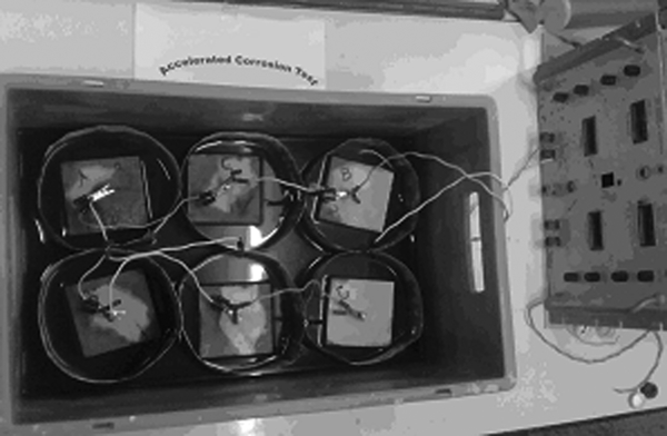
Current induced accelerated corrosion test set-up
The rapid chloride ion permeability test (RCPT) method was originally developed by the Portland Cement Association under a research programme paid for by the Federal Highway Administration. The original test method may be found in the Federal Highway Administration RD-81/119, ‘Rapid determination of the chloride permeability of concrete’. Since the test method was developed, it has been modified and adapted by various agencies and standards organisations. 16 16,17 Many concrete structures are built today with specifications calling for low permeability concrete. The construction industry accepts this test procedure as a measurement for determining chloride permeability.
For specification and quality control purposes in projects, we prefer a test that is simple to conduct and that can be performed in a short time. The rapid chloride permeability test meets these goals. First developed by Whiting in 1981,18 the RCPT has had results that correlate well with the results from the classical 90 day salt ponding test. The RCPT is performed by monitoring the amount of electrical current that passes through a sample of 50 mm thick by 100 mm in diameter in 6 h. Figure 4 shows the schematic diagram of the ASTM C1202 test set-up for RCPT. A voltage of 60 V dc is maintained across the ends of the sample throughout the test. One lead is immersed in a 3·5%NaCl solution and the other in a 0·3M NaOH solution.19
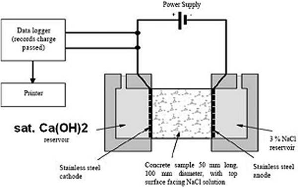
Schematic diagram for RCPT arrangement
After the RCPT, the cylinders were sliced to 1 cm thick. Core samples were taken from the cathodic side to the anodic side, 1 cm apart. The cores were taken at 1, 2, 3, 4 and 5 cm. After cutting, the samples were put in separate bags, and an identification mark was put in each bag. Then, the samples were crushed into powder to pass a 600 μm sieve. After the sample was obtained in powder form, chloride analysis was completed by argentometric titration method according to the following steps.
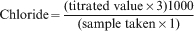
The sample solution was prepared in the ratio of 1∶3, i.e. 20 g of sample powder dissolved in 60 mL of distilled water. For the titration, 10 mL of sample water pipetted out, and two drops of phenolphthalein solution was added as indicator. The solution colour turns pink. Since the concrete sample solution was a base, it has to be neutralised. For this titration, a dilute H2SO4 was used. The colour changes from pink to colourless. After this, two drops of potassium chromate indicator was added. The colour changes to yellow, which is titrated against 0·01 N of AgNO3 solution. The colour change from yellow to reddish brown gives the titrated value. From this value, the chloride amount (ppm) in each sample was determined using equation (2) A
Results and discussion
Design mix
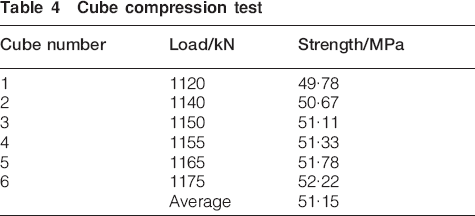
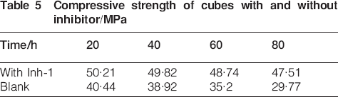
It has been proposed to cast the cubes and cylinders in M-40 grade concrete. According to the IS code, the mix design was performed and the cubes were cast according to the mix design, and they are tested. The target mean strength of the mix is 49·24 MPa. After 28 days of curing, the cubes are tested in a universal testing machine (80 T capacity), as per IS 4031:1968. The cube compression test results are shown in Table 4, which confirms the required mean strength, and Table 5 gives the compression strength of the cubes cast with inhibitor compared with blank cubes and are shown in Fig. 5.
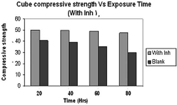
Compressive strength versus exposure time graph
Cube compression test
Compressive strength of cubes with and without inhibitor/MPa
Current induced accelerated corrosion on reinforced cube specimens
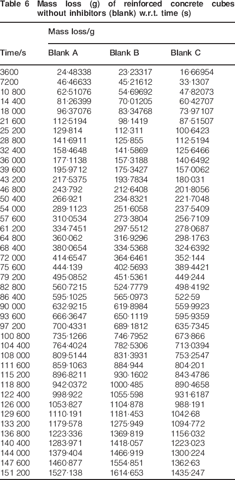
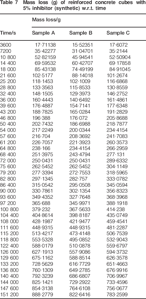
The results obtained in the present work indicate that the inhibition mechanism of the preventive inhibitor is not focused on the corrosion rate but on the corrosion amount based on the applied current. In this study, the volume change of reinforcing bars based on the amount of applied electric current is measured. From Fig. 6a, for the cube specimen without inhibitor, i.e. blank, it reveals that in the corrosion up to 12 h, there is a non-uniform loss of mass that is observed, and up to 17 h, a stable loss of mass is observed, which shows a passive film formation. After 17 h, there is a sudden increase in mass loss that suggests that the passive layer was breached and the rate of corrosion is increased. Figure 6b shows the graph of mass loss versus time for the cube specimens cast with the inhibitor. It shows that up to 8 h, there is a non-uniform mass loss, which may be due to initial hydration reactions in the concrete. However, from 8 to 30 h, a steady loss of mass that might be due to a thick passive layer formation on the steel surface reinforced in concrete is observed. The mass loss of the reinforced concrete cubes without inhibitors (blank) with respect to (w.r.t.) time and with inhibitor is given in the Table 6 Tables 6 and 7 respectively. The mass loss after 42 h for the reinforced cubes cast with inhibitor is 783 g as compared to the 1435 g of that cast without inhibitor.
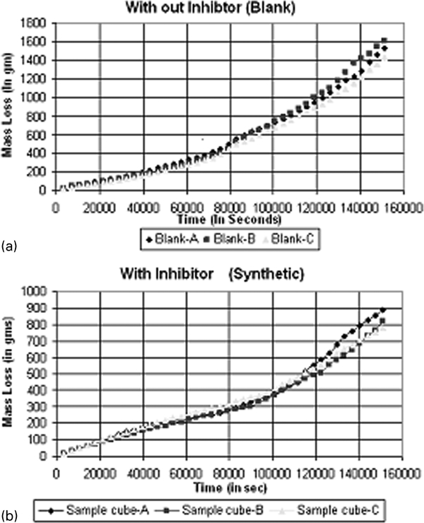
Current induced accelerated test on reinforced concrete specimen a without and b with inhibitor
Mass loss (g) of reinforced concrete cubes without inhibitors (blank) w.r.t. time (s)
Mass loss (g) of reinforced concrete cubes with 5% inhibitor (synthetic) w.r.t. time
The results suggest that the inhibitor molecules are able to induce some corrosion activity during the first hours of contact with the reinforced steel surface in the concrete, probably displacing some hydrated layers of the iron oxides/hydroxides surface film in order to create more favourable anchorage sites for the formation of the protection inhibitor layer. The inhibitor layer seems to cover the entire surface blocking the active sites and the total impedance of the system increasing continuously. In addition, due to the formation of a homogeneous layer on the steel surface and strongly decreasing the corrosion activity on the surface, creating an insulating layer, the behaviour is approached that of a capacitor.
Rapid chloride permeability test
The RCPT was conducted on 28 day old concrete samples containing the new triazine derivative inhibitor of 5% optimum concentration as corrosion inhibiting admixtures. The object of the test was to evaluate the performance of the inhibitor with concrete mixture compared with a control sample with no corrosion inhibitors. The test results showed that 670, 751 and 898 C passed for one corrosion inhibiting admixture that is in between 100 and 1000 C, i.e. the chloride permeability rating is very low. In addition, 2020, 2456 and 3835 C passing for control samples without the corrosion inhibitor means that the chloride permeability rating is moderate according to ASTM C1202.
There has been a great deal of debate over this test method because of the large variations in the results on companion test specimens. The ASTM method shows that the results of two properly conducted tests by the same operator on concrete samples from the same batch may differ as much as 42%.
Chemical analysis after RCPT
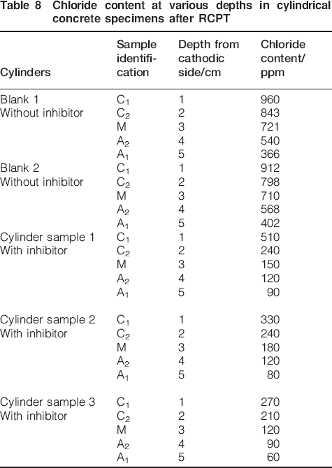
Table 8 shows the results of the chemical analysis. This result shows a gradual increase in chloride content. This indicates the rapid penetration of chloride ions while impressing current. The chloride content was decreasing gradually from cathode to anode. Figure 7 shows the chloride content at various depths in the corroded cubes.
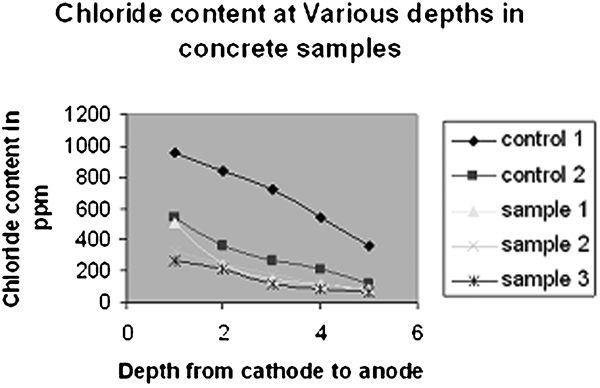
Chloride content at various depths in concrete specimens with inhibitor
Chloride content at various depths in cylindrical concrete specimens after RCPT
Computational studies
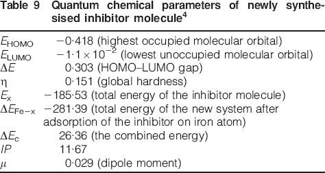
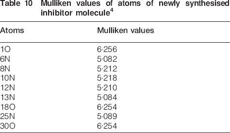
The computational studies and de novo design of inhibitor molecule are performed by Cheminformatics tools in our previous study.13 The ab initio calculations are performed by MOPAC version 6.0020 with restricted Hartree–Fock (RHF) level using AM1 semi-empirical method and ZINDO version 3.521 with restricted Hartree–Fock type and INDO/1 method in Cerius2 software22 using a powerful SGI computer. The following parameters are considered: highest occupied molecular orbital E HOMO, lowest unoccupied molecular orbital E LUMO, HOMO–LUMO gap ΔE, global hardness η, total energy of the inhibitor molecule E x, total energy of the new system after adsorption of the inhibitor on iron atom ΔE Fe-x, the combined energy ΔE c, ionisation potential IP and dipole moment μ. The values of the mentioned parameters are shown in Table 9. The localisation of the HOMO and LUMO orbitals in its optimised conformation of the inhibitor molecule is shown in Fig. 8. The Mulliken values of the atoms of the inhibitor molecule are given in Table 10.
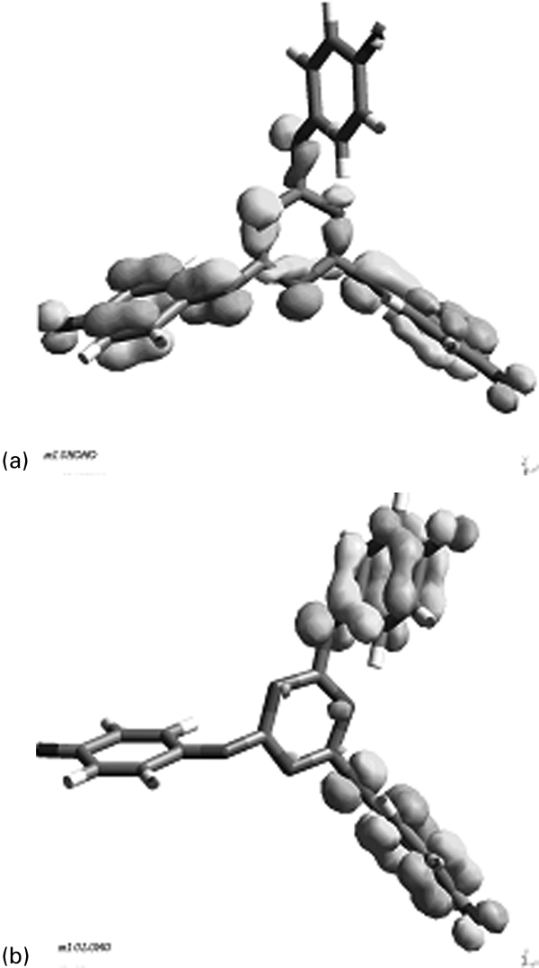
Localisation of a HOMO and b LUMO orbitals in its optimised conformation of inhibitor molecule
Quantum chemical parameters of newly synthesised inhibitor molecule4
Mulliken values of atoms of newly synthesised inhibitor molecule4
Mechanism of inhibition
The nitrogen atoms are the major adsorption centres for their interactions with the metal surface. The adsorption of these nitrogen compounds on the metal surface can occur directly on the basis of donor acceptor interaction between the π electrons of the ring and the vacant d orbital of the transition metal surface atoms. Hence, in this case, the metals are an electron acceptor and the electron donators are the nitrogen atoms of the triazine derivative. This adsorption process affects the cathodic and anodic reactions in different extents. The negative site in the electron donating molecule is usually the reactive centres. They adsorb on the cathodic sites and inhibit the hydrogen evolution, and the adsorption on the anodic inhibits the dissolution of iron.
The charge transfer interactions within a molecular complex forming an electron donor and an electron acceptor involving a resonance with a transfer of charge from donor to acceptor are shown by Mulliken. The formation of these complexes is based on the interaction of the energetically high lying HOMO of the donor with a low energy LUMO of the acceptor. Nitrogen containing ring compounds are one of the major organic donors and hence have the inhibitive property. The probable mode of inhibition of the inhibitor and the reinforced steel in concrete is shown in Fig. 9.
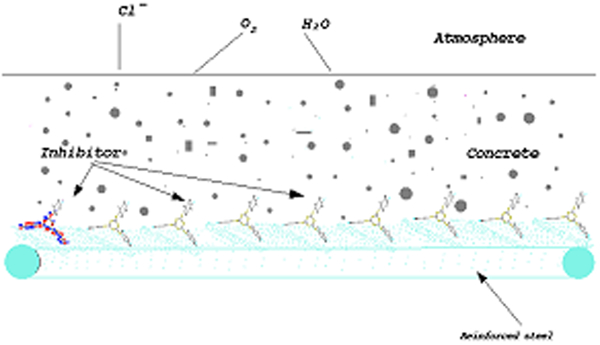
Mode of inhibition of inhibitor molecules on reinforced steel in concrete
Conclusions
The organic inhibitor studied in this work reduces the corrosion rate of the reinforcing steel in concrete interstitial electrolyte contaminated with 3·5% of sodium chloride. The mechanism by which the preventive inhibitor adsorbs on the surface seems to involve an initial increase in the activity on the steel surface. Later, the anodic activity may be reduced. The test inhibitor is effective even when a strong corrosion activity already exits on the surface. The inhibitor adsorbs well on the active site, produces a stable and protective film and is able to delay the occurrence of chloride induced corrosion. The use of an organic inhibitor reduces the ingress of chlorides by filling concrete pores and blocking the porosity of concrete by the formation of complex compounds. From the results obtained, it is concluded that the corrosion rate is very less when 5% concentration of the inhibitor is used and its inhibition efficiency shown is 85%, which are in reasonable good agreement with the results obtained from electrochemical studies performed in simulated pore solution with 3% inhibitor concentration.13 This evolution suggests a strong inhibition of the dissolution processes occurring on the surface. It was found from the results obtained that the chloride diffusion in the specimen containing inhibitors is from two to four times lower than that in concrete without inhibitors.
Footnotes
Acknowledgements
This work was performed by the support of three organisations. I sincerely thank my PhD guide Dr Y. Kalpana, BHEL R&D, Hyderabad, for her help in the electroanalysis part and Dr K. Kumar, Council of Scientific and Industrial Research, Karaikudi, for his support in the concrete laboratory process.