
Abstract
Relationships between deteriorated coating surface conditions of laboratory test panels determined by image processing software and coating impedance data collected with electrochemical impedance spectroscopy (EIS) were investigated. A unique relationship was found between the log |Z|0·1 values of experimental EIS data and the corresponding deteriorated area ratios determined by the image processing method. A well defined one to one relationship was also found between log |Z|0·1 values and log (R po) values extracted through EIS data fitting analysis. This study demonstrates that estimation of log (R po) at a certain deterioration stage is feasible via field image processing alone without running in situ EIS measurements and going through time consuming EIS fitting analysis. A field coating maintenance program established by this methodology can be an effective tool for bridge maintenance engineers who need to make timely decisions on coating repair/rehabilitation work based on the quantitative ‘visual’ image scan results and ‘invisible’ coating pore resistance.
Introduction
Application of protective coatings is the most common method for protection of steel, which is one of the primary materials used for modern transportation infrastructure. However, the protective coatings are subject to continuous deterioration due to exposure to oxygen, water, ultraviolet light, salts and corrosion. Consequently, the service life of the coatings is much shorter than that of steel structures. Accurate diagnosis of the present level of coating deterioration and prediction of remaining service life are critical steps before implementing adequate coating repair/maintenance strategies at right times.
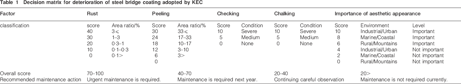
At the Korea Expressway Corporation (KEC), deterioration of steel bridge coatings is usually rated by rust, peeling, checking, chalking and importance of aesthetic appearance. A combination of these conditional factors is used to formulate a decision matrix, as listed in Table 1, and a specific maintenance action is recommended based on the overall score of the bridge coatings. Since traditional coating inspections and condition assessments are mainly carried out by visual surveys with naked eyes, inspectors’ skill and experience make a difference in outcomes with regard to the accuracy of coating condition assessment and the recommendation of timely maintenance actions. In addition, there is a lack of experienced coating inspectors within KEC, whereas the number of steel bridges keeps increasing in the highway system under KEC's management. In these circumstances, more efficient and time saving coating inspection methodologies are desirable to enhance KEC's ability to maintain its steel bridge inventory properly. Especially, rust and peeling are the most influencing factors, as they can result in up to 70% of total scores in the worst case according to the criteria in Table 1. Coating inspectors generally give scores for deteriorated areas exhibiting rust and peeling by comparing their conditions to standard photographs, but it is not easy to determine the rust or peeling area ratio accurately. In an effort to improve coating inspection capabilities, highway maintenance authorities in Japan and Korea had developed quantitative coating evaluation programs using image processing methods. Such programs available in Japan are COMS,1 developed by the Public Works Research Institute, and Paint View,2 developed by the Japan Highway Public Corporation. Recently, the third steel bridge coating diagnosing program, so called the steel bridge coating diagnosing system (BCD), was developed by Cheong et al. of KEC, which can differentiate types of coating deterioration such as rust, blisters and peeling by employing different algorithms from the Japanese programs.3,4 The BCD's ability to differentiate types of coating deterioration enhances the accuracy and efficiency in diagnosing coating condition because deterioration scores calculated with the rust or peeling area ratio will be different.
Decision matrix for deterioration of steel bridge coating adopted by KEC
Although these image processing methods can make it possible to evaluate various types of ‘visible’ coating deterioration rapidly, it cannot provide ‘invisible’ coating information such as holidays, accumulation of water in coating and underfilm corrosion. Electrochemical impedance spectroscopy (EIS) has been utilised for evaluating steel bridge coating degradation because of its non-invasive nature and ability to detect subtle changes in coating properties. The US Federal Highway Administration performed a laboratory study on the performance evaluation of steel bridge coating systems using EIS.5 There are other coating studies reported using EIS to obtain additional information that could not be available via traditional test methods for characterising the performance of organic coatings in corrosive environments.6 – 10 For example, in laboratory studies with epoxy coated steel and epoxy coated magnesium alloy, Scully and Hensley found a correlation between the magnitude of the low frequency impedance and long term coating deterioration. 11 11,12 In other work, Hack and Scully used EIS to quantify defective areas of coated steels in seawater through the breakpoint frequency method.13
Electrochemical impedance spectroscopy offers excellent capabilities for research grade coating evaluations in laboratory environments; application of such a sophisticated technique in outdoor environments has been challenging from the viewpoint of portability and measurement difficulties encountered in the field. Specifically, it requires extra site logistics and equipment, including a portable electric power source, a dc–ac converter, and, in some cases, a Faraday cage to shield the test areas from electromagnetic interference emitted from the surrounding. Measurements using EIS can also be cumbersome in the field, as installation of an electrochemical test cell is sometimes difficult, especially on the bottom side of flanges where coating deterioration tends to concentrate, and measurement noise is often unavoidable due to bridge vibration and moving traffic.
Based on previous work done by Gui and Kelly,14 who observed correlations between deteriorated area of coating and electrochemical parameters (interfacial resistance and double layer capacitance), a novel research idea was conceived to explore ways to gather ‘visible’ and ‘invisible’ information of field coatings accurately by means of a visual image processing method alone, without having to use EIS in the field. With this objective in mind, a small scale, in-house research study was carried out using two types of primers at the Expressway and Transportation Research Institute, the research arm of KEC, located in Dong-Tan, Korea. This paper discusses some of the preliminary findings pertaining to a correlation identified between quantitative coating deterioration data of coated test panels determined by the KEC developed image processing program BCD and the ‘invisible’ coating characterisation of the same test panels measured with EIS.
Experimental
Materials and accelerated testing
An epoxy primer and an acrylic primer used for steel bridge maintenance were selected for this study. A total of 17 test panels were prepared using degreased 150×75×2·5 mm hot rolled steel plates with 30-40 μm of surface roughness by grit blast cleaning per near white blast cleaning (Society for Protective Coatings SP-10). The first group of 11 panels was coated with an epoxy primer, and the second group of six panels was coated with an acrylic primer. Table 2 summarises details of the individual test panels. Both primers were applied by air spray method.
Coating systems and type of accelerated testing
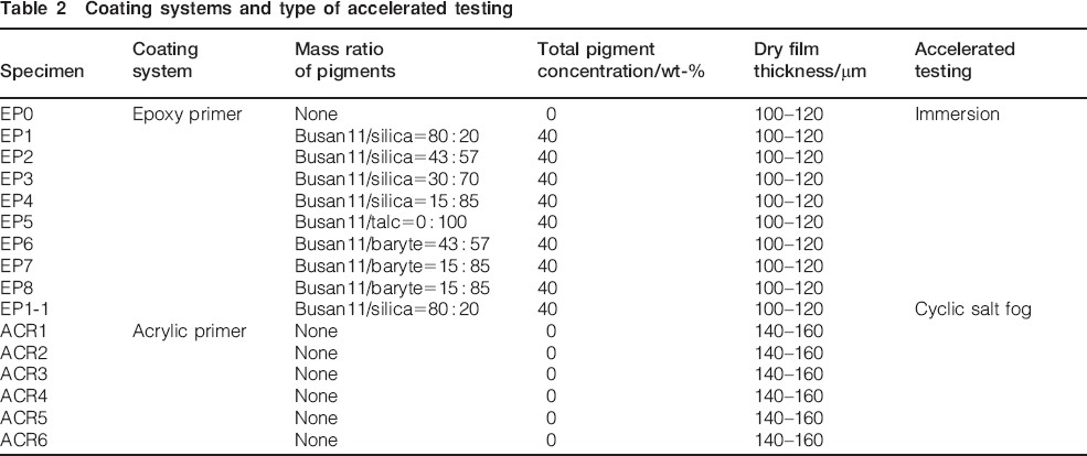
To formulate slightly different epoxy primer coatings, Bisphenol A type epoxy resin and polyamide hardener were used in combination with different mix proportions of an anticorrosive pigment (Busan11) and an extender pigment (silica, talc or barite), as shown in Table 2. In order to study impedance change upon growth of rust spots only (no blisters), an additional epoxy primer specimen (EP1-1) was prepared with the same mix proportion as EP1 during the laboratory study. A back-up specimen (EP0) was also prepared. All the acrylic primer specimens were coated with a commercially available acrylic primer product made in Korea for steel bridges.
In order to expedite the coating deterioration process, two accelerated laboratory test regimes were adopted as follows:
immersion test for eight epoxy primer specimens (EP1–EP8) in 0·5M NaCl solution for 15 weeks (2520 h)
cyclic salt fog test for the additional epoxy primer specimen (EP1-1) and all of the six acrylic primer specimens (ACR1–ACR6) repeated with 8 h cycles according to ISO 14993.
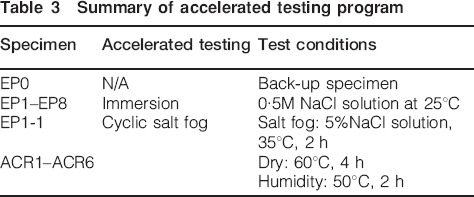
Table 3 summarises the detailed test conditions. The immersion test condition was considered a relatively mild environment, which was mainly intended to investigate the effects of pigment type and content on coating deterioration. The cyclic salt fog test was introduced as a more aggressive environment that was designed to accelerate development of coating defects and result in impedance reduction. For control purpose, the back-up epoxy primer specimen was set aside without exposure to accelerated testing.
Summary of accelerated testing program
Quantitative evaluation of surface coating deterioration by image processing method
As a means to evaluate the surface coating deterioration quantitatively, the area ratios of rust spots and blisters with respect to the entire test area were calculated using BCD. This image processing software employs a pattern recognition method to estimate deteriorated areas on any coating surface having rust spots, blisters and peeling problems. 3 3,4 It is currently used by KEC bridge maintenance engineers who want to choose the most effective time to take action with regard to deteriorating coating systems. Typically, the engineers take digital photographic images of the deteriorating coating at the site, run the coating diagnosing program and calculate the extent of deteriorated surface areas quantitatively. From this information, they can determine the best time to intervene for coating repairs and/or other maintenance activities. A captured screen view of the executed BCD is shown in Fig. 1. The target area used by the image processing software was 12·6 cm2, as shown in Fig. 2.
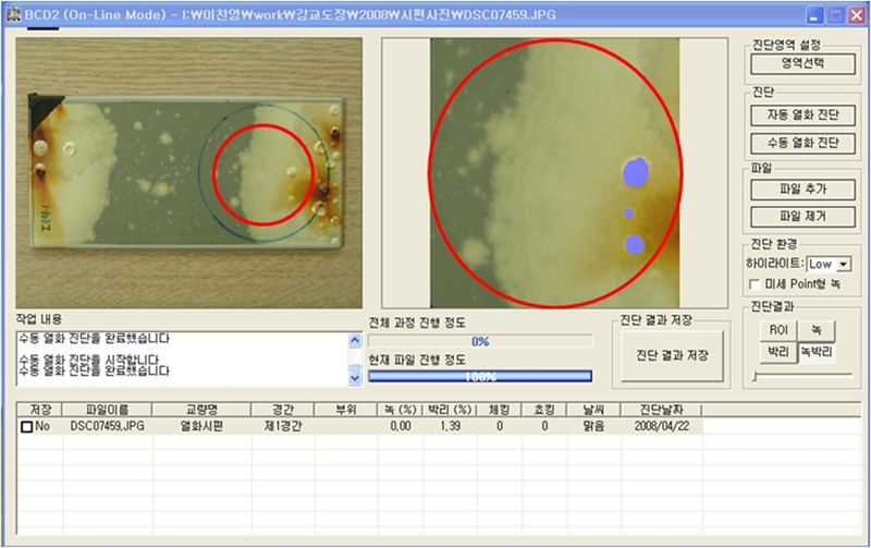
Captured screen of coating diagnosis program BCD
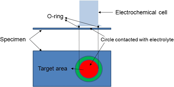
Location of target area and EIS test cell
Electrochemical impedance spectroscopy measurement and data analysis
During the accelerated testing, EIS measurements were carried out using a Solartron 1252A frequency response analyser coupled with a Solartron 1296 dielectric interface. The following parameters were used, as summarised in Table 4:
Electrochemical impedance spectroscopy measurement parameters
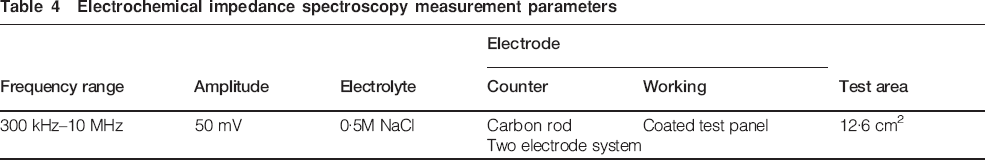
sweeping frequency range: 300 kHz to 10 mHz
voltage amplitude: 50 mV
electrolyte: 0·5M NaCl solution
test area: 12·6 cm2 (coincides with the target area for the imaging software).
A two-electrode test cell was used for EIS measurements. A carbon rod was immersed in the NaCl solution as the counter and reference electrodes, and a coated steel panel was the working electrode. Before each EIS measurement on a test panel, initial conditioning in the electrolyte was made for 30 min to ensure reaching its stable corrosion potential.
Once the experimental EIS data were collected, they were analysed with appropriate equivalent circuit models that theoretically describe coating degradation process using discrete circuit elements such as resistors, capacitors and inductors. Commercial EIS curve fitting software ZView was used for the fitting work in this study. After estimating values of circuit elements for a particular EIS data using the ‘instant fit’ function in the software, those estimates were entered into the selected circuit model followed by execution of the software. The fitting work for the particular EIS data was considered final when the lowest error percentage was yielded during the fitting process. At the end, the fitted curve was placed over the experimental EIS data to ensure good agreement between the two EIS spectra.
Test results and discussion
Evaluation for epoxy primer
For eight epoxy primer coated test panels exposed to the immersion test, the image analysis and EIS measurements were carried out after 2520 h testing was completed. Primary forms of coating surface deterioration observed were blisters and rust spots, as shown in Fig. 3. Among the eight panels, the surface condition of EP1 containing 80 wt-% anticorrosive and 20 wt-% extender pigment (silica) appeared to be the best, without any signs of coating deterioration. A scan of the surface using BCD also did not reveal any detectable defects. The superior performance of EP1 can be attributed to the highest amount of anticorrosive pigment content among the epoxy primer specimens. The other specimens developed various degrees of surface deterioration, as shown in Fig. 3, which were captured by the BCD.
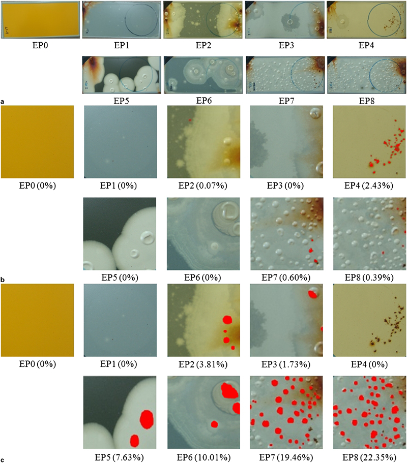
Visual imaging processing results for epoxy primer specimens
The relationship between the logarithmic value of impedance modulus at 0·1 Hz (log |Z|0·1) of the epoxy primer specimens and their corresponding total deteriorated area ratios is shown in Fig. 4. For two specimens (EP0 and EP1) exhibiting no visual defects, log |Z|0·1 values were more than 9 (1×10⁹ Ω cm2) and near 8 (1×10⁸ Ω cm2) respectively. For the remaining specimens that had developed coating defects identified by BCD, the log |Z|0·1 values were less than 4 (1×10⁴ Ω cm2). According to Linda et al.,15 the anticipated performance of a coating based on log |Z|0·1 value can be classified as follows: a coating offers (i) excellent protection if log |Z|0·1 is >10, (ii) good protection if log |Z|0·1 is >8 and (iii) poor protection if log |Z|0·1 is ⩽4. Graphical presentation of log |Z|0·1 classifications is shown in Fig. 5. According to Fig. 4, EIS was very sensitive in picking up subtle changes in coating such that even minor coating defects lowered the log |Z|0·1 significantly. An exponential decay regression model with R 2 of 0·75 is included in Fig. 4 to describe such a unique relationship of log |Z|0·1 values versus the total deteriorated area ratios.
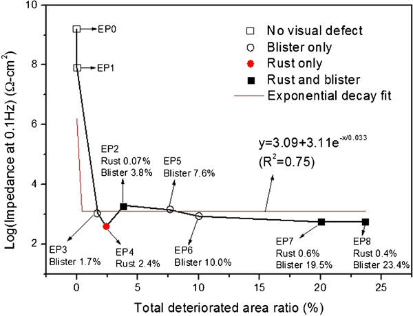
Log |Z|0·1 versus total deteriorated area ratio for epoxy primer specimens
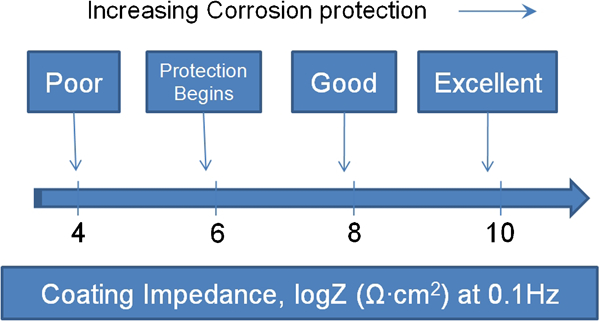
Classification of coating impedance for various coating conditions15
In general, the development of rust spots had greater contribution to the reduction of impedance than blisters did such that test panels containing only small rust spots had lower impedance than those with blisters alone. It can be hypothesised that the blistered coating still could provide some degree of electrical insulation as long as there were no cracks in the blistered coating film.
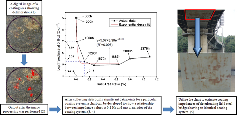
In order to understand more about impedance change in response to growth of rust spots only (no blisters), an additional experiment was carried out with an extra test panel (EP1-1) that had the same coating composition as EP1. After 1200 h of cyclic salt fog testing, the first rust spot appeared, and the total rust area ratio and the corresponding log |Z|0·1 were 0·013% and 7 (or 9·67×106 Ω cm2) respectively (see Fig. 6). Considering a defect free condition for EP1 throughout the 2520 h of immersion testing, it is apparent that the cyclic salt fog exposure was a more aggressive environment than the constant immersion condition. When the rust area ratio increased to 0·13% at 1290 h, log |Z|0·1 decreased to 5·3 (or 1·89×105 Ω cm2). An exponential decay regression model with R 2 of 0·997 was used to describe the relationship between the rust data and the corresponding log |Z|0·1 values except for the last two data points collected at 2000 and 2360 h. As observed in Fig. 4, this regression model also depicts the sudden loss of coating barrier property in terms of coating impedance as soon as small defects developed. Based on the criteria in Fig. 6, where good coating protection can begin at log |Z|0·1>6, it can be stated that the epoxy primer coated specimens employed in this study can provide adequate protection until the rust area ratio increases up to 0·026% according to the regression model. The increased log |Z|0·1 despite increased rust areas at the last two measurements might be explained by a theory that clogging of coating pores and initial rust spots with dense corrosion products resulted in increased impedance.
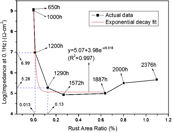
Change of log |Z|0·1 as function of rust development for epoxy primer specimen (EP1-1)
Evaluation for acrylic primer
The image scans and EIS measurements for the acrylic primer coated test panels were carried out periodically during the accelerated testing. Some of the image scan results are shown in Fig. 7. Blisters did not develop, and all of the defects were rust spots. The rust area ratios for the acrylic test panels varied significantly, ranging from 0·36% (the far left image on the first row in Fig. 7) to 56·85% (the far right image on the third row in Fig. 7). When the coating defect appeared on ACR1 and ACR5 at 650 h, their rust area ratios were 0·36 and 0·98% respectively, and their log |Z|0·1 values were 4·49 (or 3·06×104 Ω cm2) and 5·65 (or 4·47×105 Ω cm2) respectively. This observation suggests that the extent of rust formation (rust area ratio) and coating impedance (log |Z|0·1) was not always related, but a general relationship between them existed, as shown in Fig. 8. Such a relationship is similar to that of the epoxy primer counterpart in that coating impedance sharply dropped when the rust spots developed, with a similar exponential decay regression model. Poor performance of the acrylic primer specimens is supported by two observations, i.e. extensive coating deterioration and continuous reduction of log |Z|0·1 during the final stage of accelerated testing.
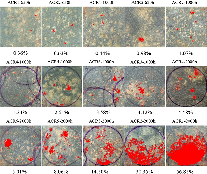
Image processing results showing various levels of rust development on acrylic primer specimens
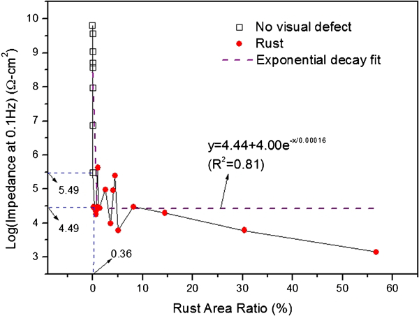
Change of log |Z|0·1 as function of rust development for acrylic primer specimens
Electrochemical impedance spectroscopy data analysis
Examples of EIS curve fitting work for an epoxy primer specimen and an acrylic primer specimen are shown in Figs. 9 and 10 respectively. In both cases, good agreement was achieved between the experimental and fitted EIS spectra. In the epoxy primer case (Fig. 9), an equivalent circuit model having two time constants was used. The first time constant that appeared in the high frequency region was related to coating (a parallel circuit of pore resistance R po and coating capacitance), and the second time constant that appeared in the low frequency region was related to coating/steel interface (a parallel circuit of charge transfer resistance R ct and a constant phase element representing non-ideal double layer capacitance). This model is the most common circuit model to represent the electrochemical behaviour of coated steel experiencing corrosion at the coating/steel interface. The equivalent circuit model used in Fig. 10 was different from the one in Fig. 9 in that the second time constant portion was replaced with a diffusion related element, which is often suitable to fit EIS data without a distinctive second time constant in the low frequency region. Physical interpretation of this element is diffusion process towards the coating/steel interface. All the EIS data were fitted with one of the two models, and the quality of the other EIS fitting results was similar to these examples above.
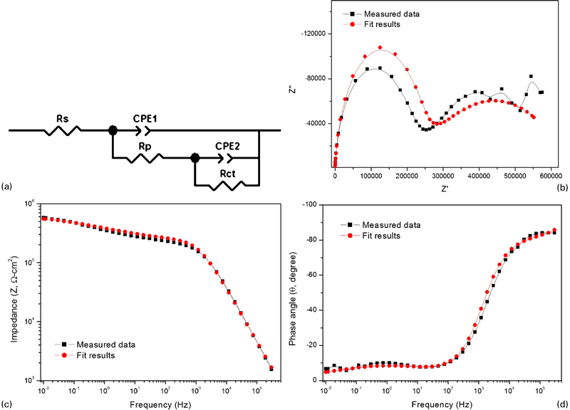
Example of equivalent circuit model fitting work for epoxy primer specimen
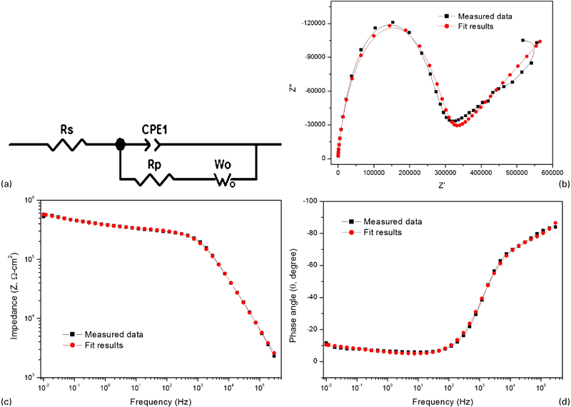
Example of equivalent circuit model fitting work for acrylic primer specimen
Figure 11 Figures 11 and 12 show the one to one relationships between log |Z|0·1 values taken from EIS experimental data and log (R po) values obtained from the fitted results of the EIS data for the epoxy primer specimens and the acrylic primer specimens respectively. Both relationships were described with similar linear regression models with R 2 of 0·99. Based on this, it can be stated that the most important coating barrier property, i.e. coating resistance R po, of a coating system can be reasonably estimated by reading log |Z|0·1 off from its experimental EIS data without going through elaborate and time consuming curve fitting analysis.
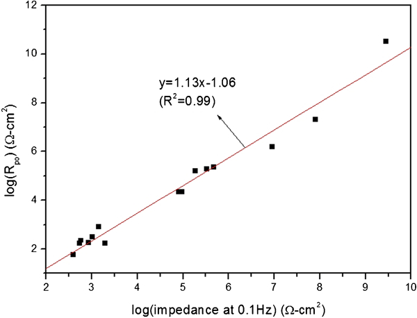
Correlation between log (R po) and log |Z|0·1 for epoxy primer specimens
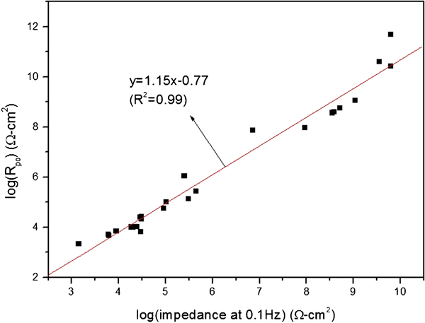
Correlation between log (R po) and log |Z|0·1 for acrylic primer specimens
Discussion
In previous sections, unique relationships were found for the primer specimens in terms of (i) degree of surface coating deterioration calculated by image processing software versus log |Z|0·1 data and (ii) log |Z|0·1 values versus log (R po) data. Even though the test results obtained in this study are too small to find statistically significant models, the work presented here demonstrates that there is a great potential to develop a field applicable methodology to estimate a specific coating system's impedance data solely based on field coating image scan results. If a sufficient number of coating photographs were taken in the various areas followed by BCD image analysis and EIS data are collected at those areas for a particular coating system, this approach can create a large database for the particular coating system with coating deterioration area ratios at various deterioration stages and the corresponding log |Z|0·1 values. Therefore, the maintenance engineers can determine reasonably accurate coating barrier property [log |Z|0·1 and log (R po)] without running in situ EIS measurements on other bridges coated with the same coating system in the following steps: (i) taking digital images of the deteriorated coating areas, (ii) running the image processing software and calculating the extent of deteriorated area ratios, (iii) estimating log |Z|0·1 from the predetermined relationship between deteriorated area ratios and log |Z|0·1 values, (iv) estimating log (R po) from the other relationship [log |Z|0·1 values versus log (R po) data] and (v) taking a course of action based on field image scan results of the deteriorated coating system and their estimated coating impedance data [log |Z|0·1 and log (R po)]. This concept is graphically described in Fig. 13. This methodology would be more accurate and effective than conventional visual evaluation using naked eyes for maintenance engineers who need to deal with coating repair/rehabilitation, as the decision making process takes into account both the quantitative ‘visual’ image scan results and the estimated ‘invisible’ coating pore resistance. It is KEC's objective to expand the current study to try the above strategy for the most popular coating systems used in highway steel bridges in the near future.
Concept of novel approach to in situ evaluation of steel bridge coatings
Conclusions
Based on limited accelerated testing results and subsequent data analyses, the following conclusions were made.
Based on the number of coating defects and the rate of deterioration, it was observed that a cyclic salt fog exposure was a more aggressive environment compared with the constant immersion exposure. The image processing software BCD was able to identify area ratios of the coating deterioration with respect to the total target area. In general, development of rust spots had greater contribution to the reduction of impedance than blisters did.
All of the EIS data collected in this study were fitted with either of two equivalent circuit models. The first equivalent circuit model had two time constants that are related to the coating itself and the coating/steel interface respectively. The other model contained a diffusion related element, which is often suitable to fit EIS data without a distinctive second time constant in the low frequency region.
For each type of primer coated specimen, a unique relationship was found between log |Z|0·1 values of experimental EIS data and the corresponding total deteriorated area ratios determined by BCD. The relationships could be described with exponential decay regression models.
Furthermore, each primer had a well defined one to one relationship between log |Z|0·1 values and log (R po) values extracted from the EIS data fitting results. These relationships were described with linear regression models with R 2 of 0·99. From this, the most important coating barrier property, i.e. coating resistance R po, of a coating system can be reasonably estimated by its log |Z|0·1 value, which in turn can be estimated by another relationship between log |Z|0·1 values and total surface deteriorated area ratio, as described above.
With this approach, one can estimate R po via field image processing data of deteriorated areas without running in situ EIS measurements and going through time consuming EIS fitting analysis provided that a sufficient volume of field image processing data and their EIS data are collected in advance for the particular coating system.
This study demonstrates that estimation of coating impedance data [log (R po)] at a certain deterioration stage is feasible via image processing alone, and that this methodology would be more accurate and effective than conventional visual evaluation using naked eyes for bridge maintenance engineers who need to deal with coating repair/rehabilitation, as the decision making process takes into account both the quantitative ‘visual’ image scan results and the estimated ‘invisible’ coating pore resistance.