
Abstract
Owing to their large and curved shape, blade castings, a key component for heavy hydro turbines, are susceptible to deformation during casting and heat treatment. In the present paper, the stress analysis of a blade casting during both casting and heat treatment is performed. The coupled thermo-stress and thermo-phase transformation stress models are used for casting and heat treatment respectively. Machining allowance distribution is used as the deformation criterion and an algorithm of inverse deformation determination is presented. The mechanical properties of the martensitic stainless steel ZG0Cr13Ni4Mo (13Cr–5Ni–1Mo) at different temperatures are measured under as cast and heat treated status. Finally, the inverse deformation of the blade during both casting and heat treatment processes is obtained, and a series of sections of the blade casting with inverse deformation design are given for pattern making. The calculated deformation results are compared to the measured one, and they are basically in agreement.
Introduction
Deformation is often found during casting production, especially in large and thin sectioned castings. Deformation occurs during casting and during heat treatment process as well, in which heating and cooling, phase transformation and stress are all involved. The stress analysis is necessary to predict the deformation of casting.1–3 However, current researches are just for casting process, and the mechanical properties are not clarified with respect to the cast microstructure and phase transformation after solidification is neglected. Phase transformation is considered in the numerical simulation of heat treatment for forgings.4–6 Research about the stress analysis of castings during both casting and heat treatment processes is rarely found. Hydro turbine blade castings are of large, thin sectioned and curved shape; they are susceptible to deformation in casting process and successive heat treatment process as well. In the production, inverse deformation has to be applied to compensate for the deformation, which is usually determined by experience in foundries, and to prevent the effect of deformation, great machining allowance is given, which results into insufficiency and long machining time.
In the present paper, the coupled thermo-stress phase transformation model is established, and the mechanical properties of a typical stainless steel for hydro turbine castings are measured. A new method is presented for the description of deformation, and an inverse deformation algorithm is proposed.
The stress analysis of the blade casting for Three Gorges Project during casting and heat treatment is performed. Its inverse deformation is obtained for pattern making, and the deformation is compared to the measured results.
Coupling of thermo-stress phase transformation
During casting and heat treatment of castings, heating and cooling, phase transformation and stress evolution are closely related, as illustrated in Fig. 1. Heating and cooling results in phase transformation, while latent heat released during phase transformation feeds back to temperature field. Stress evolves due to non-uniform heating and cooling. For this Cr–Ni stainless steel, martensite transforms into austenite during heating and holding above Ac3, while austenite transforms into martensite during quenching process. The specific volumes of phases are different, which also resulted in stress, and although there is external stress, plasticity is induced by the transformation from austenite to martensite.
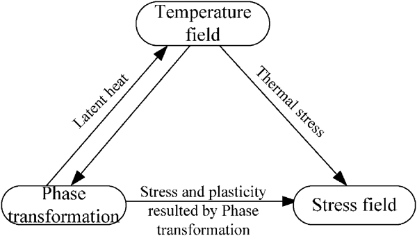
Schematic diagram of temperature, phase transformation and stress analysis
Heat transfer constitution equation
The heat transfer during casting and heat treatment is controlled by the Fourier equation. The heat transfer at the boundary conditions of casting/mould, mould/air and casting/air are convection and radiation.
Phase transformation models
During heating, process austenisation happens, while austenite transformed into martensite during cooling by forced air. Austenisation is diffusion controlled phase transformation, which can be simplified as the function of temperature, as follows
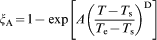
The fraction of martensite during phase transformation from austenite to martensite, a kind of non-diffusion controlled, is denoted by the Koistinen–Marburger equation as
Governing equations for strains
During heat treatment, the total strain consists of elastic, plastic, thermal, phase transformation strains and plasticity induced by phase transformation as well.
The phase transformation strain ϵtr is a result of the difference between specific volumes of new and old phases

The phase transformation induced plasticity ϵtp evolves, although no yielding occurs. It is determined by the Greenwood–Johnson model

Mechanical properties and phase transformation constants for ZG0Cr13Ni4Mo
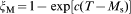
ZG0Cr13Ni4Mo (13Cr–4Ni–1Mo) is a typical stainless steel for hydro turbine castings. It undergoes martensite transformation during 276–280°C no matter what the cooling rate is. The mechanical properties of different microstructures at high temperatures are measured, as shown in Fig. 2. Great difference can be seen between the properties of austenite and martensite, and the constants for phase transformation model (equations (1) and (2)) and phase transformation induced plasticity (equation (4)) are calculated based on measured results, as shown in Table 1.

Thermal mechanical properties of stainless steel ZG0Cr13Ni4Mo
Constants for simulation of turbine blade casting
Deformation prediction and inverse deformation determination
Displacement result can be obtained from stress analysis, while it includes both contraction and deformation. Here, machining allowance distribution is used to describe deformation for casting process. No deformation means that there is sufficient and even machining allowance everywhere. If there is no machining allowance or the matching allowance is too small, inverse deformation is given to compensate for the insufficient part. Therefore, calculation iterates until sufficient and even machining allowance is achieved everywhere. The criterion for machining allowance is estimated by the formula as shown below

For the heat treatment process, the displacement is projected to the normal direction of the local surface area to comply with the requirement of machining process. Then, the normal component of displacement is used as the judgment of deformation, which is fed back as inverse deformation to modify the finite element model of the initial design. Iterations are carried out until no deformation is achieved. The systematic flowchart of the stress analysis, deformation description and inverse deformation feedback are shown in Fig. 3. Finally, the inverse deformation during casting and heat treatment can be summed and output to STL file for guidance of pattern making.
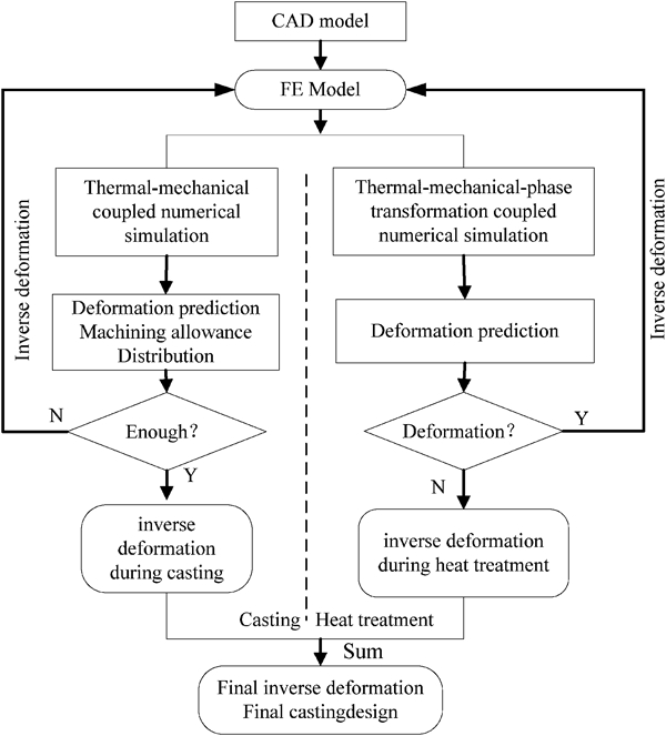
Flow chart of finite difference method/finite element model system
The numerical simulation is carried out by using an integrated finite difference method/finite element model system for thermal stress analysis of shaped castings. During casting process, stress analysis is performed by ANSYS, and the phase transformation is neglected for slow cooling rate and strong constraints by sand mould. The stress analysis of heat treatment process is realised in DEFORM-3D with the coupling of thermal phase transformation stress.
Numerical simulation of blade casting
The hydro turbine blade casting for the Three Gorges Power Plant, made of ZG0Cr13Ni4Mo stainless steel, is 28·5 tons in weight with height of 5300 mm and width of 4660 mm. It is cast in resin bonded sand mould with shake-out at 80°C. After casting, it undergoes normalising and two temperings. During normalising, the casting is cooled in air or forced airflow. During the simulation of casting process, the mould retardation is considered by contact element method.
The machining allowance of each iteration and the final inverse deformation for casting process are shown in Fig. 1. For the first iteration, the machining allowance at the left bottom corner area of the original model is negative, and it varies from −2·4 to 59·3 mm, which means that the distribution of the machining allowance is not even enough either. Inverse deformation, opposite to the direction of deformation, is given to delete deformation finally. After four cycles, the distribution of machining allowance is quite even, and the inverse deformation is shown in Fig. 4c; positive value means inverse deformation outward the front view, while negative value means opposite direction. Since corners A and B are of opposite bending direction, then their inverse deformations are also of opposite direction. As compared to Fig. 4d, it can be seen that the inverse deformations of these two corners are in good agreement with the initial design.
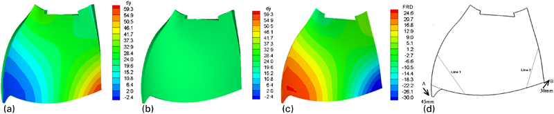
Distribution of calculated machining allowances of front side and final inverse deformation during casting process
Temperature difference, phase transformation difference and deformation results of these corners A and B, which are of the biggest curvature during heat treatment process, are shown in Fig. 5. It can be seen that the displacement mainly varies during the normalisation process, while it varies slightly during tempering processes. Great variation appears during the cooling process of normalisation. The directions of displacements of corners A and B are opposite; the final displacement tends to make the turbine flatter. The displacement variation is closely related to temperature difference curve and the volume fraction difference of phase transformation. The displacement peaks or valleys occur with the peaks of temperature difference and volume fraction difference. The final deformation of corner A is −28·4 mm, while that of corner B is 21·4 mm.
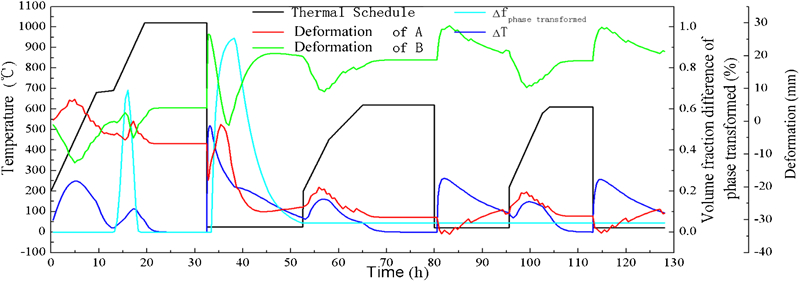
Deformation variation of corners A and B during heat treatment
Figure 6 illustrates the deformation and inverse deformation results during normalisation process, neglecting the minor deformation during tempering. The reference points for deformation calculation are points O, P and Q. The deformation of corner A is −26·6 mm while that of corner B after the first iteration is 19·9 mm; negative sign means the opposite direction. After the second cycle, the maximum deformation reduces to 0·24 mm, almost no deformation. The inverse deformation of corner A (26·5 mm) and corner B (−19·7 mm) is mainly applied to the casting. The calculated and measured deformations, i.e. shape difference between before and after heat treatment, are compared, and they are basically in agreement, as shown in Fig. 7. In comparison, points O′, P′ and Q′ are used.
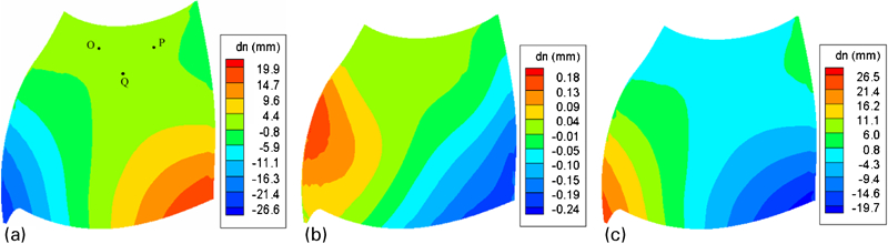
Determination of inverse deformation during heat treatment

Comparison of calculated and measured deformation without added inverse deformation
The inverse deformation during both casting process and heat treatment processes are summed up, then the design of the pattern is obtained, as shown in Fig. 8.
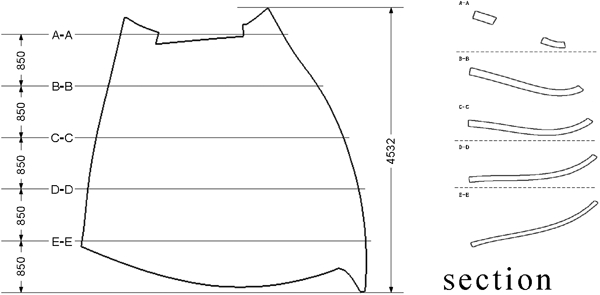
Design considering total inverse deformation
Conclusions
The coupled thermo-phase transformation stress model is established. The through process numerical simulation is realised for castings, i.e. during both casting and heat treatment. Machining allowance distribution is used as the deformation criterion for casting process, while normal component of displacement is used for heat treatment process. Inverse deformation algorithm is present for both deformation criteria. The hydro turbine blade casting for Three Gorges Project is simulated, deformation is predicted and inverse deformation is acquired by iteration algorithm. Deformation occurs during casting and heat treatment at the same degree, while deformation occurs mainly in normalising process during heat treatment. The inverse deformation is summed up during both casting and heat treatment processes, then the design of casting is obtained, which serves as a guide for pattern making.
Footnotes
Acknowledgements
The project is funded by the National Science and Technology Program (project nos. 2007BAF02B07 and 2007BAF02B02) and the Major National Sci-Tech Project (project no. 2009ZX04014-082), China.