
Abstract
In Part 1 of this paper, the development of a semiempirical model of a carbon in leach (CIL)/carbon in pulp (CIP) plant for recovery of gold and silver was detailed. With appropriate practical parameters, the model was able to reproduce typical tank profiles for gold and silver contained in the solids, solution and active carbon. The model was used in a series of simulations to explore the influence on plant performance of: (1) circuit design encompassing tank size and number, and tankage configuration; (2) using some of the initial tanks for leaching only (CIP); (3) the impact of a thickener recycling a percentage of tailings solution to the head of the circuit; (4) leaching and adsorption parameters; (5) operational parameters such as ore feed rate and percent solids in the slurry; and (6) rate of countercurrent movement of active carbon. The results of these simulations highlight factors which need to be considered in the design and optimisation of a CIL/CIP circuit and provide an insight into identifying deficiencies in performance and the possible ways to counteract them by manipulation of the factors above.
Introduction
The efficiency of a mineral processing operation is determined by many factors. One group of these relates to the basic plant design. This will have been determined by an appreciation of the properties of the ore body: its mineralogy and its response to various processing techniques as determined by laboratory tests with some appreciation of the degree of variability in such properties likely to be encountered. Many variables plant in a mineral processing plant are beyond the immediate control of the operator. The scope of the present study is limited to variables which could be examined by the model developed in Part 1 of this paper (Stewart, 2012).
Interaction of the design and operating variables may be very complex so that it is not easy to intuitively predict the results of an operational or configuration change. The model allowed examination of such changes as were within its scope and permitted patterns of response to be identified which could lead to a quick assessment of the best approach to dealing with shortcomings in recovery of gold and silver: the main criteria for assessing a carbon in leach (CIP)/carbon in pulp (CIL) plant.
Circuit design
Number and size of tanks: Constant total residence time
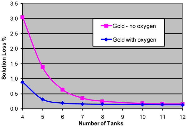
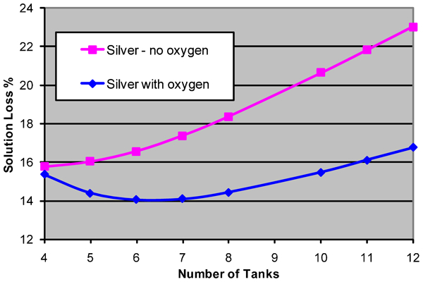
The effect of additional tanks of the same size on recovery was investigated by maintaining a feed rate of 250 t h−1 at 38% solids with a carbon advance rate of 10 t/day. The number of tanks was varied from 4 to 12 in the one case changing tank size so that the total tankage volume remained constant at 8400 m3 and total residence time did not change (16·7 h) and in the other by maintaining the individual tanks at 840 m3 while changing the number, so that the corresponding residence time ranged from 6·7 to 20 h. The solids and solution losses for gold and silver for constant total tankage volume are shown in Figs. 1–4.
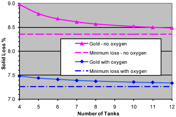
Solid loss for gold, constant total tankage volume
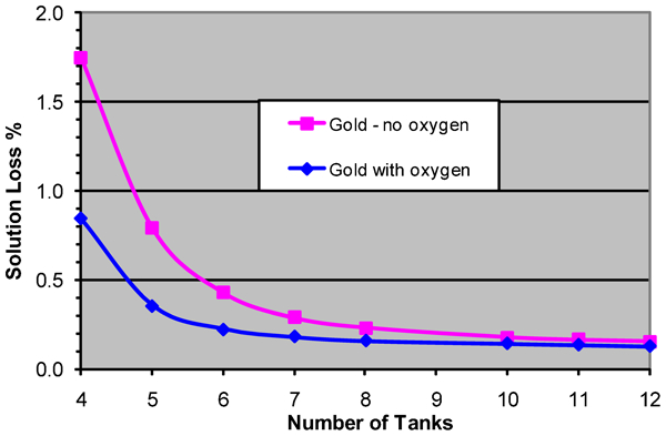
Solution loss for gold, constant total tankage volume
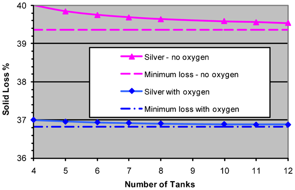
Solid loss for silver, constant total tankage volume
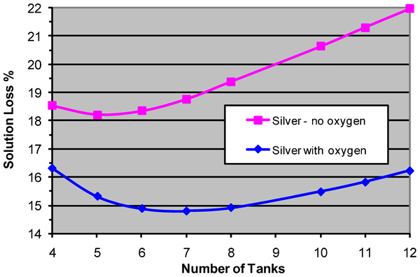
Solution loss for silver, constant total tankage volume
As the number of tanks is increased, the flow approaches ‘plug flow’ ultimately corresponding to a near infinite number of small tanks or a batch leach. This would give the most efficient leaching and the minimum loss in solids for the set residence time (as shown on the graphs). With increasing number of tanks in the simulation, the solid loss progressively approaches this value.
The solution loss for gold follows a similar pattern, decreasing with increasing number of tanks whether oxygen is used or not. Four tanks are insufficient for adsorption and seven is clearly enough.
However, the pattern of solution loss for silver is quite different and appears to be anomalous. The loss passes through a minimum at five tanks for no oxygen and at seven tanks when oxygen is used. It then increases steadily. This means that from the point of view of losses of silver in solution, there can be too many tanks. Such behaviour would appear to indicate an inadequate carbon advance rate. However, if the carbon rate is increased sufficiently to reduce solution loss of silver to low levels and avoid this silver behaviour, the final loading of gold on the carbon becomes undesirably low.
Some insight into the interactions underlying this behaviour can be gained from the profile of solution loss down the bank: as shown in Figs. 5 and 6 for the case with no oxygen enhancement. The solution concentration passes though a maximum which depends on the number of tanks in the bank and is accentuated by late leaching. This behaviour has been observed frequently in practice confirming the realism of the simulations. Interchanging the adsorption parameters between gold and silver provides further insight (Figs. 7 and 8). A maximum emerges in the gold solution profiles for seven or more tanks and the maxima and final solution concentrations for silver are greatly reduced.
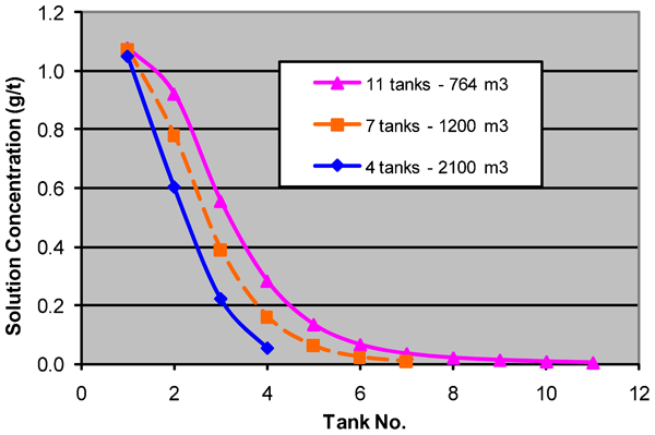
Solution profiles for gold (no oxygen)
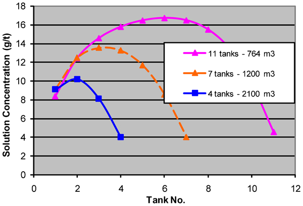
Solution profiles for silver (no oxygen)
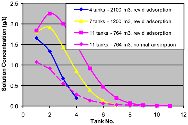
Solution profiles for gold with interchanged adsorption parameters
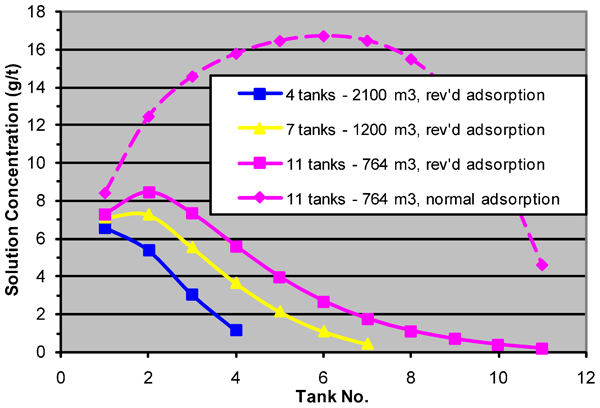
Solution profiles for silver with interchanged adsorption parameters
This shows that the behaviour is a function of the interaction of leaching rates, adsorption relationships and carbon advance rates. In a situation where the carbon rate is insufficient to carry all leached values from the circuit or leaching occurs late, fresh carbon entering the circuit at the last tank meets a high solution concentration and is quickly loaded. The carbon thus carries values back up the train. However, in the earlier tanks, insufficient leaching has occurred to provide solution concentrations which will sustain the carbon loadings of the entering carbon. The values therefore desorb until equilibrium is attained, creating a maximum as the progressively more lightly loaded carbon moves up the bank. The behaviour is less pronounced with fewer tanks as the residence time in each tank is greater producing more leaching in the earlier tanks, higher early solution concentrations, higher final carbon loadings and lower final solution losses.
Number of tanks of constant size: Increasing total residence time
The complementary tank change is adding more tanks of the same size, thus increasing residence time. This may be done in order to gain more recovery or to permit a feedrate increase. There is a steady increase in leaching of both gold and silver with added tanks which tails off as the fast leaching values are depleted (see Figs. 2 and 3 in Part 1 of this paper). The change in solution loss with added 840 m3 tanks is shown in Fig. 9 and 10. These show that while solution loss of gold decreases steadily with additional tanks and residence time, the behaviour of silver is more complex. However, even though solution loss of silver may increase, the total recovery increases with extra tanks. Solution profiles are very similar to those in Figs. 3 and 4 and it would seem that in this case, the carbon advance rate and adsorption capability are inadequate to recover all the additional silver which has been leached as tanks are added.
Solution loss of gold with additional 840 m3 tanks
Solution loss of silver with additional 840 m3 tanks
One of the questions which is relevant is whether additional recovery can justify any additional tanks. On the assumptions of 8000 h of operation at 250 t h−1, 38% solids, 5 ppm gold, 35 ppm silver and $1600/oz gold, $28/oz silver, the annual revenue which can be credited to each additional tank may be estimated in order to illustrate the significance of these enhanced recoveries. The results are shown in Table 1.
Additional annual revenue resulting from an additional tank
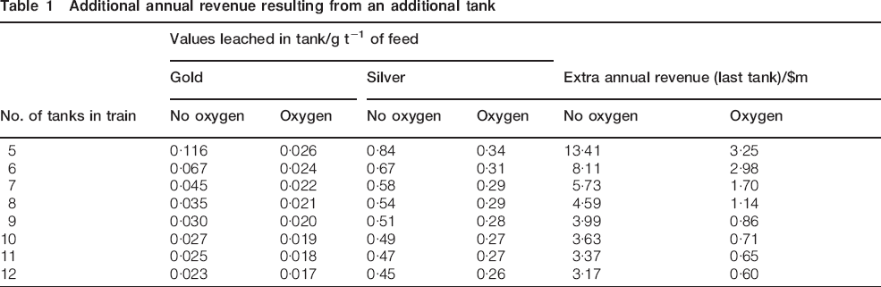
On this rather simplistic analysis, if an additional installed tank costs $2m and must be paid out in 2 years, when oxygen is used, an eighth tank is justified and the ninth is doubtful. When oxygen is not used, then at least a twelfth tank is indicated. In this latter case, the circuit would probably need to be re-evaluated on the basis of two parallel banks. A proper analysis would need to take operating and maintenance costs of additional tanks and pertinent consideration of the cost of capital. It is of interest that in this example, even though the head assay of silver is seven times that of gold, on average about 80% of the additional revenue as a tank is added comes from additional gold recovery. Conclusions from an analysis such as this are very dependent on head grades, feedrate, carbon rate and other model parameters as well as metal prices and thus, a proper analysis needs to be related to a specific plant and point in time to have true significance.
Parallel banks
Metallurgically, two parallel banks is equivalent to doubling the tank size with half the number of tanks. The configuration was simulated by both halving the feedrate and the carbon advance rate. A summary of results for comparing two parallel banks of 4, 5 and 6 tanks each with banks of 8, 10 and 12 tanks is given in Table 2. Differences are that the loss in the parallel arrangement is less than the loss in the corresponding serial bank.
Differences in losses for parallel and serial banks
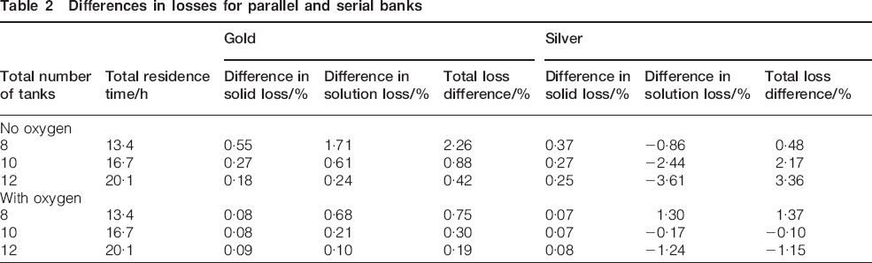
The table shows that losses in solid recovery are lower when the tanks are arranged in series than as two parallel banks. The same is true for solution loss of gold and most total losses. However, solution loss of silver is generally less for the parallel bank arrangement because the longer residence time in the early tanks gives more leaching and a higher solution concentration in these tanks resulting in higher final carbon loadings and improved solution recovery of silver. When oxygen is used, all differences are less. Overall, the study shows that metallurgically the serial arrangement is preferable. However, for practical operation, a parallel arrangement would often be preferred. If the differences are expressed in terms of annual revenue, then a more clearcut situation emerges as Table 3 below shows.
Revenue differences serial and parallel bank arrangements
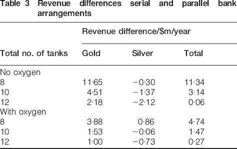
Differences in gold recovery are again much more financially significant than those for silver. Regardless of whether oxygen is used or not, eight tanks are clearly better operated in series and the practical advantages of two parallel banks of six would probably easily outweigh financial imperatives for operating 12 tanks in series. For 10 tanks, parallel banks are probably preferred if oxygen is used but not otherwise. Once again for any particular plant, the results will depend on all the relevant circumstances, but the simulation provides a means to bring them together and make a valid conclusion.
Thickener
Water fed to a tailings thickener is split between the thickened underflow and the clear overflow which is recycled for reuse in the plant. Values in solution split with the water. Operation with maximum dilution water added to thickener feed, consistent with water balance constraints, and at maximum per cent solids in the underflow maximises return of values. Figures 11 and 12 show the effect of such a thickener on solution concentrations for a bank of 10 tanks of 840 m3 where 70% of values in solution are recycled. As the solution loss of gold is low, the recycle has little impact on the solution profiles, virtually all the recycled gold in solution being adsorbed. The points for operation with the thickener in Fig. 11 are virtually indistinguishable from the curves for operation with no thickener. Nonetheless, even the small solution losses of gold are reduced by 70% and the thickener is a significant safeguard against solution losses in case of an aberration in leaching or adsorption.
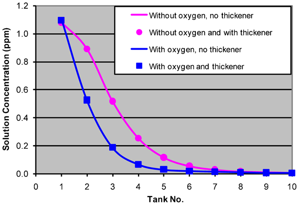
Effect of thickener on gold solution profiles for 10 tanks
Effect of thickener on silver solution profiles, 10 tanks
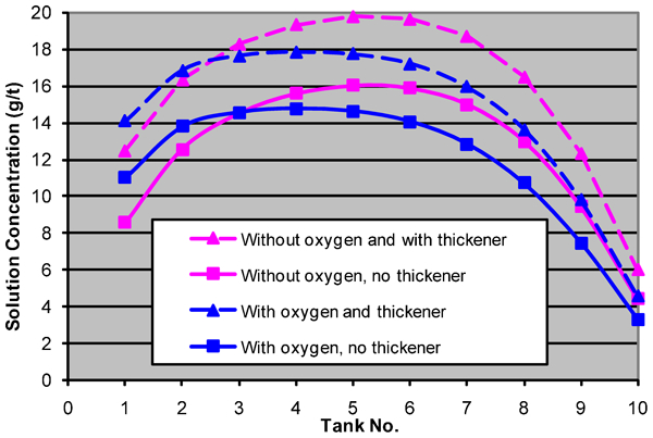
For silver with a major recycle of values, the whole profile is raised. Higher concentrations increase carbon loadings and thus, overall recoveries of solution silver are increased. In this example, 85% of the silver in the recycle is effectively recovered and final solution loss is 40% of what it would be in the absence of a thickener (e.g. with oxygen, the solution loss is reduced from 15·5% to 6·4%). A tailings thickener is thus a very effective way of reducing solution loss. A tailings thickener can also impact positively on loss of unused cyanide and cyanide destruction requirements.
Leach only tanks
It is common practice to use early tanks in a bank purely for leaching (see Fig. 1 in Part 1). The impact of this configuration on solution profiles is shown in Figs. 13 and 14. For gold, the concentration rises steadily in leach only tanks from tank to tank. This is shown as a separate relationship in Fig. 13. Once carbon is introduced, the gold concentration falls steadily to the end of the bank. As there is little solution loss and the carbon rate was constant at 10 t/day, the carbon loading is unchanged and the concentration in the tank from which carbon is extracted is the same regardless of how many tanks are leach only. As the number of tanks used for adsorption drops, there is a very small increase in final solution concentration and solution loss rises slightly.
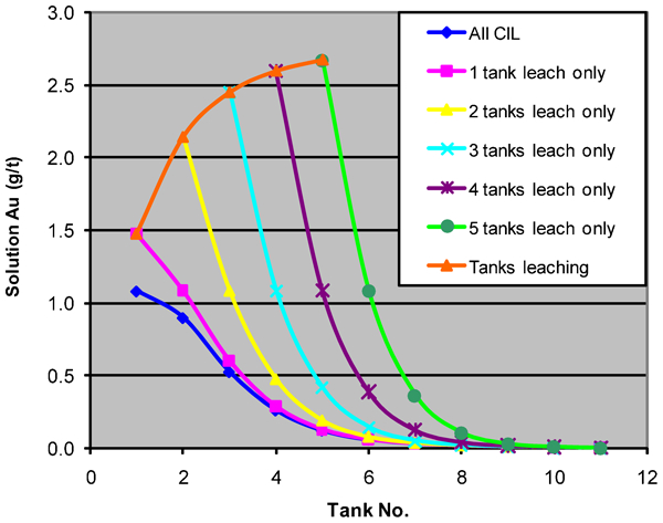
Solution profiles for gold for hybrid CIP) circuit
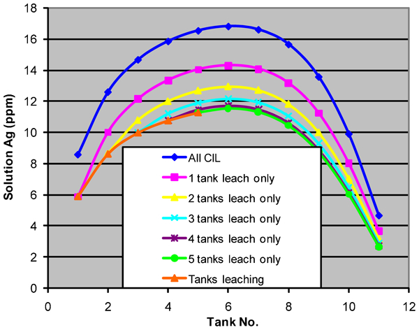
Solution profiles for silver for hybrid (CIP) circuit
For silver (Fig. 14), the concentration also rises steadily for the leach only tanks. However, even for five ‘leach only’ tanks, the concentration continues to rise for tanks with carbon by the mechanisms discussed previously. Carbon is extracted from the tanks with progressively higher solution concentrations as the number of leach only tanks is increased. Carbon loadings therefore increase and solution losses fall. The gain in silver recovery with one leach only tank is over 3%. For two leach only tanks, the additional gain in recovery is 2·4% when oxygen is not used and only 1·0% with oxygen. In going from two leach only tanks to three, the further gains are 1·3% and 0·4% respectively. One or possibly two leach only tanks would appear to be usually justified with three or more leach only tanks unlikely to be of much value.
This is another method of reducing solution losses of silver and the use of one or two leach only tanks generally gives a more robust circuit. However, the use of leach only tanks leaves the circuit vulnerable to losses with ores subject to preg-robbing as leached values can be adsorbed by the preg-robbing components before the active carbon meets the pregnant solution. This evidences itself as an apparent increase in solid loss.
Operational variables
Ore feedrate
Feedrate is one of the primary operational variables and there can be a constant pressure on operators to increase feedrate without full regard to the consequences. Figures 15–18 show the effect of feedrate change on losses in the solids and solution. When solid losses are plotted against the log of the feedrate (as shown), the data give almost a straight line plot. By maintaining the same leaching parameters, these data implicitly assume that feedrate change has not affected the size distribution of the feed ore and thus, the overall leaching rate. In general, a higher feedrate would be expected to coarsen the size distribution and thus, reduce the fraction of fast leaching values. Solid losses would increase further as a result.
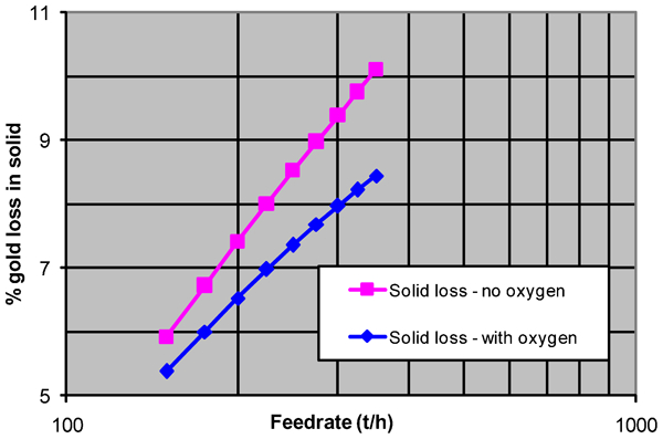
The effect of feedrate on loss of gold in solid
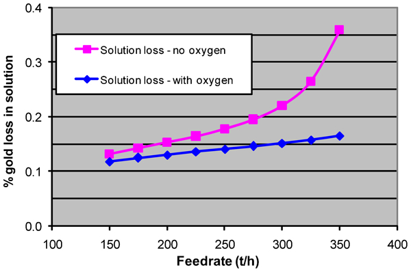
The effect of feedrate on loss of gold in solution
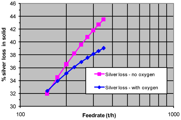
The effect of feedrate on loss of silver in solid
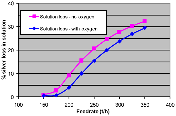
The effect of feedrate on loss of silver in solution
Solution losses for silver form a sigmoid shaped plot when a wide range of feedrates is used. The data for gold indicate only the start of such a shape as the solution losses for gold are all low.
A proper evaluation of the most desirable feedrate requires an assessment of the NPV of the remaining ore reserves for a range of feedrate and recovery combinations for average ore. The physical modelling can thus be combined with economic modelling.
Percentage of solids in the slurry
As with the selection of feedrate, the percentage of solids in the feed slurry may be subject to various constraints. If there is no thickener between the grinding circuit and the CIL plant, then the maximum per cent solids for CIL may be set by grinding or classification considerations. Viscosity and ease of flow from tank to tank may also limit the allowable concentration in the tanks. High viscosity or inadequate stirring at high per cent solids could hamper both leaching and adsorption rates and at high slurry SG, the active carbon may tend to rise to the surface. This can only be assessed by appropriate testwork and this analysis assumes that there are no such limitations. Deviations from predicted behaviour could signal the presence of such effects. Table 4 below shows the effect of per cent solids on recovery of gold and silver. The basic conditions are feedrate of 250 t h−1 and carbon advance rate of 10 t/day for a 10 tank plant (tanks in series).
Effect of per cent solids in slurry on recovery
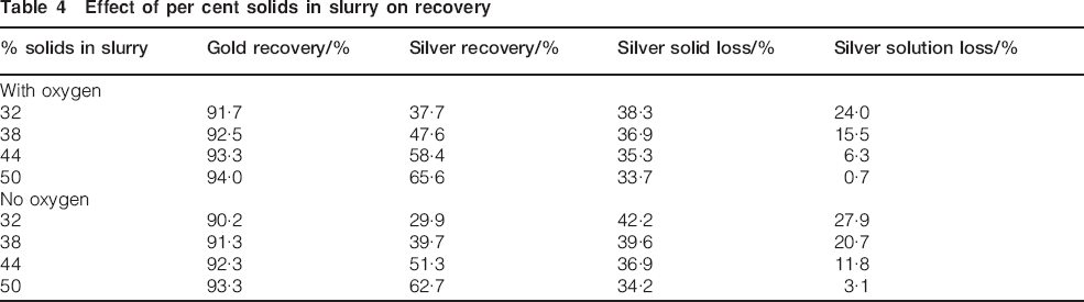
The table shows that increase in per cent solids potentially brings very significant increases in recovery. This can be best illustrated by comparison with the effect of changing feedrate. Thus, in order to bring the same increase in recovery in gold as changing per cent solids from 38% to 44%, the feedrate must be reduced from 250 to 200 t h−1. For silver, a reduction to 209 t h−1 is required. For gold, the solution loss is low for all per cent solids. In contrast for silver, although there is a substantial reduction in loss in solids, the major improvement for increasing per cent solids is in reduced solution loss.
There are two mechanisms which are operative: a higher per cent solid reduces slurry flow for the same solids feedrate and hence, increases residence time and the leaching in each tank, and second the values are leached into a smaller volume of solution enhancing initial concentrations and final carbon loadings. At 50% solids, the flow of solution is half that at 33% solids. With improved carbon loadings, the overall mass balance is improved and final concentrations of values and solution loss fall. Figure 19 shows these effects for solution concentration of silver. The broad conclusion is that it is preferable to operate at the highest practical per cent solids.
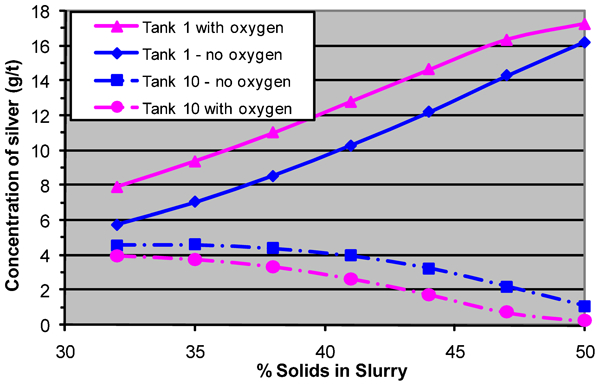
Effect of % solids on solution concentrations of silver in Tank 1 and Tank 10
Carbon advance rate
Carbon advance rate impacts directly on the overall mass balance and hence on solution loss as discussed earlier. Figure 20 shows that solution loss for gold remains low until the carbon advance rate is reduced to about 7 t/day. For silver, significant solution losses commence as the carbon advance rate drops below 14 t/day (Fig. 21). For both metals, solution losses are reduced with the use of oxygen.
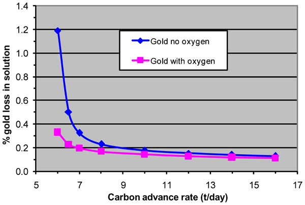
Effect of carbon advance rate on loss of gold in solution
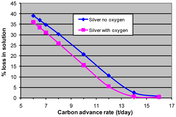
Effect of carbon advance rate on loss of silver in solution
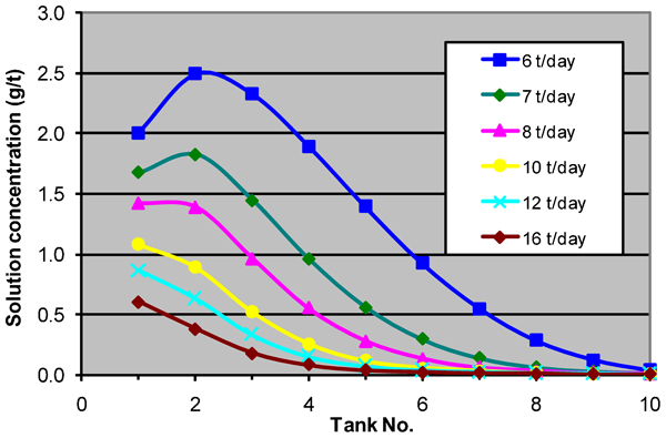
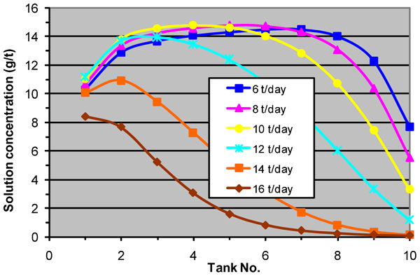
The onset of significant solution loss can be related to solution profiles. These are shown in Figs. 22 and 23. When the solution concentration peaks in Tank 2, as for 7 t/day for gold without oxygen, then the circuit is prone to significant solution losses if there is any further reduction in carbon advance rate (or reduction in adsorptive capacity). The same association can be seen for silver with oxygen when the carbon rate is 14 t/day. In this way, solution profiles can be a useful diagnostic tool in indicating when the plant may be on the verge of serious solution losses.
Solution profiles of gold (no oxygen, various carbon rates, 10 tanks)
Solution profiles of silver (with oxygen, various carbon rates, 10 tanks)
Using equations (3), (5) and (7) in Part 1 of this paper, the theoretical minimum carbon advance rate for complete adsorption is given by
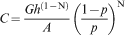
Ultimately, the maximum carbon rate possible may be limited by the ability to move carbon through the circuit and the capacity of the stripping and regeneration circuits. Hence, it may not be always possible to avoid solution loss in a particular plant, especially of silver, when there is slow leaching or poor adsorption without a major, undesirable reduction in fresh feedrate of ore.
The residual loading on barren carbon can have an undesirable effect on final solution concentration. An increase in gold loading on ‘barren’ carbon from 20 to 55 ppm adds 0·2% to solution loss of gold and an increase in silver loading from 200 to 650 ppm adds 2% to silver loss. In this study, such barren carbon loadings corresponded to prudent limits.
Leaching rates and adsorption equilibria
Throughout, this paper has contrasted the behaviour of four different sets of leaching parameters: gold with and without oxygen and silver with and without oxygen. This has shown that when oxygen is used, the larger fast leaching fraction and faster leaching rates of this fraction are always advantageous. The associated slower leaching rates of the slow leaching fraction never had a deleterious impact overall. Silver demonstrated the behaviour of values which were more difficult to leach but which also responded positively to oxygen addition.
To examine further the interaction of leaching and adsorption parameters, a version of the model with a single leaching rate for both metals, with leaching and adsorption in all tanks and with the base simulation conditions of 250 t h−1, 38% solids and 840 m3 tanks, was used. When a very high leaching rate of 50 h−1 was input, 99% of the leaching took place in Tank 1. In this situation with a carbon rate of 10 t/day, recovery of gold was very close to 100%, the only loss being 0·07% in solution, corresponding to the equilibrium concentration with a barren carbon loading of 20 ppm. Recovery from solution was over 98% complete in the first three tanks.
In contrast, loss of silver in solution was 24%. The silver concentration in Tank 1 was 21·3 ppm which is very close to the maximum possible for all the silver going straight into solution (21·5 ppm). Hence, carbon loadings were close to maximum. However, as discussed earlier, the carbon advance rate was inadequate for the poorer adsorption parameters for silver.
The response of gold and silver to changing the leaching rate is shown in Figs. 24–27). The solution loss of gold exhibits a maximum at a leaching rate of about 0·1 h−1 (Fig. 24). Low leaching rates correspond to ‘late leaching’ and reduced total leaching. Consequently, the quantity leached in the final tanks also goes through a maximum at this rate. With the carbon advance rate over double the theoretical minimum required for gold, any gold leached is quickly adsorbed and the final two or three tanks control solution loss as shown in Fig. 25. In a seven-tank plant, more leaching is done in the final tanks than in a 10-tank plant.
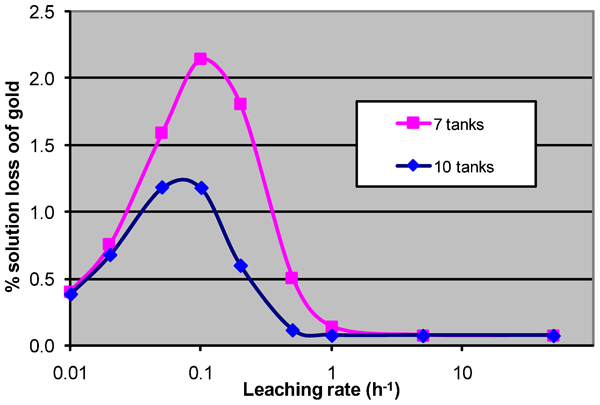
Dependence of solution loss of gold on leaching rate
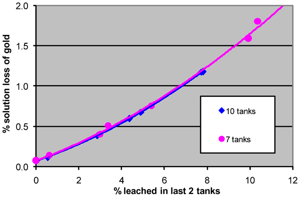
Solution loss of gold vs leaching in final two tanks
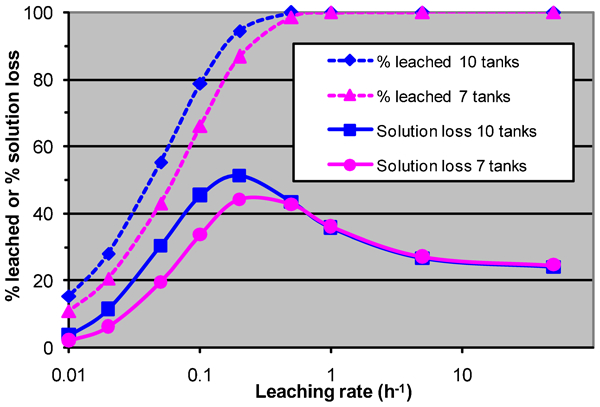
Dependence of %leached and solution loss of silver on leaching rate
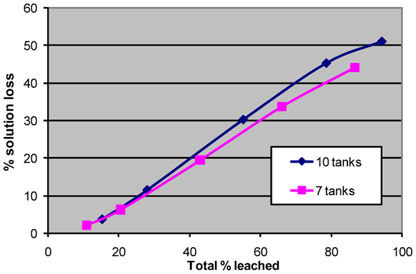
Solution loss of silver vs %leached for “α” = 0·01–0·2 h−1
An examination of the solution profiles for silver shows that a similar peak in solution loss occurs at about a rate of 0·2 h−1 (Fig. 26). At this rate, leaching of silver is about 94% for 10 tanks. As the rate is increased above 0·2 h−1 progressively more leaching is done in the early tanks, the concentration in Tank 1 approaches the theoretical maximum and final solution loss asymptotes to the value corresponding to the residual silver which cannot be adsorbed by the carbon because the carbon advance rate is less than the minimum required for full adsorption.
For lower leaching rates, because of the inadequate carbon rate combined with late leaching, a major amount of the adsorption is done in the final tanks and solution loss tends to be related to the total leached (Fig. 27). The total leached and solution loss are greater for a 10-tank plant than for a seven-tank plant for all leaching rates.
Conclusion
A simple model of a CIP/CIL circuit has proved valuable in providing insights into the complex interactions in a leaching and adsorption plant. An examination of the influence of a range of design and operating factors has indicated preferred configurations and conditions.
At least five tanks are normally required to ensure good adsorption and low solution loss. Six to nine tanks in series is preferred. Ten tanks may be arranged in series or as two parallel banks, but parallel banks are preferable for 12 tanks or more.
For the parameters used in this study (which are believed to be typical of many ores), the use of oxygen gave a circuit which was demonstrably more robust to variations in operating conditions.
The use of one or two tanks as leach only, when there is no threat of preg-robbing, provides a degree of insurance against solution losses if solids are either late leaching or adsorption parameters are unfavourable.
To ensure efficient adsorption of values the carbon advance rate should be at least 1·7 times the theoretical minimum rate which may be calculated from the feedrate, head grade, percent solids and adsorption parameters.
If solution losses are significant, a tailings thickener recycling a high percentage of tailings solution, containing values, back to the circuit will bring a major reduction in these losses. A thickener is also a significant safeguard against solution loss if there is an aberration in leaching or adsorption.
The highest percentage of solids in the slurry, consistent with the size distribution of the ground ore and flow conditions through the circuit, is advantageous in minimising loss in solids and solution. Viscosity modifiers to assist in raising % solids could be economically justifiable.
Footnotes
Acknowledgements
The model was developed whilst the author was employed at the Chatree Gold Mine, Thailand. The permission of the mine to publish this paper is gratefully acknowledged. The author would like to acknowledge the support and assistance of colleagues, who collected much of the data on which the concepts embodied in the model were based and who were always happy to discuss any of the applications or practical aspects in early development of the model. In particular, I express my gratitude to N. Phunmuang, K. Kritsanaphak and D. Morrison.
This paper was originally presented, together with Part 1 (Stewart, ![]() ), at Metallurgical Plant Design and Operating Strategies (MetPlant) 2004, 6–7 September 2004, Perth, Western Australia. It has been subsequently peer reviewed and revised for publication in Mineral Processing and Extractive Metallurgy with the kind permission of the Australasian Institute for Mining and Metallurgy.
), at Metallurgical Plant Design and Operating Strategies (MetPlant) 2004, 6–7 September 2004, Perth, Western Australia. It has been subsequently peer reviewed and revised for publication in Mineral Processing and Extractive Metallurgy with the kind permission of the Australasian Institute for Mining and Metallurgy.
This paper is part of a special issue on Australian gold processing