
Abstract
TiB2 based hard material has been fabricated by combustion synthesis from elemental powders using Fe–Al intermetallics as the binder phase. Both the crystal orientation map and the pole figures by electron backscatter diffraction analysis showed that the TiB2 particles have no preferential orientation. Preheating of the power compact is helpful to increase the relative density and to reduce the particle size of the synthesised product, which increases the hardness of the product. The highest hardness and relative density were achieved for a composition of TiB2–20 vol..-%FeAl.
Introduction
Titanium diboride (TiB2) possesses many advantages, such as high values of melting point, hardness, wear resistance and chemical and thermal stabilities.1 The range of potential application of TiB2 is wide, including impact resistant armour, cutting tools, wear resistant parts, grain refiner and all kinds of high temperature structural materials.2– 4 In addition, the high electrical conductivity4 enables machining of TiB2 material using electrical discharge machining.
However, the engineering applications of TiB2 single phase material are rather limited because of poor sinterability and low ductility. To obtain dense borides, transition metals such as iron, cobalt and nickel have been used as binder.5– 7 In such cases, the sintering temperature and heating time can be reduced, and most importantly, the grain growth of TiB2 can be limited, and the densification is enhanced.2 However, the utilisation of pure metallic phase as the binder is not desirable for hard ceramics.8 TiB2 based hard materials with the second phase of intermetallics are expected to have a unique combination of their properties, and the fabrications of FeAl/TiB2 9,10 and NiAl/TiB2 11 composites had been attempted. In the light of the high temperature strength, low density and good oxidation resistance, Fe–Al compounds such as FeAl and Fe3Al are considered suitable for the binding phase of TiB2 based hard materials used as cutting tools or moulds. In the present study, the fabrication of TiB2 based hard materials with the binder phase of Fe–Al intermetallics is attempted using combustion synthesis process from elemental powders.
The synthesis of TiB2 based materials from elemental powders is properly. Lepakova et al. 12 studied the mechanism of phase and structure formation of the Fe–Ti–B system in a combustion wave for a mixture of Ti, B and Fe powders. The results showed that the mechanism of structure formation depends significantly on the type of contact between the initial components. In the exploration of Raju et al.,13 almost full densification of TiB2 is achievable with 2·5 wt-%MoSi2. The hardness of TiB2–2·5 wt-% MoSi2 decreases with temperature, which is 27·6 GPa in room temperature, and the samples retained their maximum hardness of 10·5 GPa up to 900°C; the flexural strengths of TiB2–2·5 wt-% is 391 MPa at room temperature. Venkateswaran et al. 14 reported the processing of hard, tough transition metal borides (TiB2 based cermets sintered with 6 wt-%Cu using spark plasma sintering route). They found that the dense TiB2–6 wt-%Cu composite possess a good combination of mechanical properties, including high hardness (∼17 GPa) and moderate fracture toughness (∼7·5 MPa m1/2). These investigations encouraged us to study TiB2 based hard materials with the binder phase of Fe–Al intermetallics. The analyses of the microstructure and mechanical properties of the composites are also conducted.
Experimental
The powders of Fe (99 wt-% purity and 75 μm diameter), Al (99·5 wt-% and 150 μm), Ti (99·4 wt-% and 45 μm) and B (99 wt-% and 2 μm) were mixed to give nominal compositions of TiB2 with 20 vol.-%Fe3Al and TiB2 with 20 vol.-%FeAl, which for simplicity are denoted hereafter as TiB2/20Fe3Al and TiB2/20FeAl respectively. The sample of TiB2/20Fe was also fabricated and investigated for comparison. Powder mixtures with a small amount of ethanol added were sufficiently mixed (>60 min) by glass bar on a 80°C heating platform in air in order to prevent segregation due to the difference in the specific gravities of the different kinds of powders. Before pressing, the powder mixtures were preheated at 400°C and 120 min in vacuum furnace to completely dry the powders. The powder mixtures were pressed into a cylindrical compact with dimensions of Φ30×25 mm under a pressure of ∼570 MPa. After pressing, the compact fabricated from the preheated powder mixture was also preheated at 400°C for 120 min in a vacuum heating furnace. To avoid confusing, the following texts ‘with preheating treatment’ means the powder mixtures were preheated at 400°C and 120 min in vacuum furnace, then mixed powders were pressed into compact and the compact was also preheated at 400°C for 120 min in a vacuum heating furnace; the texts ‘without preheating treatment’ means no preheating method was applied in both periods mentioned above.
Thereafter, the compact was put into a steel can (AISI 1020 steel) with dimension of Φ32·5×45 mm. Fine Al2O3 powders (∼50 μm) were added as medium between the compact and the can. A hole was drilled in the bottom of the can with dimension of Φ4·2×5 mm, and a thermocouple was put inside the hole in order to measure the temperature of the compact. The steel can was firstly welded in one side, and after putting the compact inside, the other side of the steel can was fixed under vacuum in a pressing furnace. Then, the compact inside the can was heated in a pseudo-HIP equipment at a rate of ∼ 20°C min−1. Dried casting sand was used as pressing medium. A pressure of 20 MPa was initially applied, and the pressure was immediately raised to 84 or 168 MPa when a sudden temperature rise due to combustion synthesis was observed. The high pressure of 168 MPa was kept for 5 min.
The microstructures of the synthesised products were analysed by scanning electron microscope (SEM), electron backscatter diffraction (EBSD), electron probe microanalyser and X-ray diffraction (XRD). The mechanism properties of the products were examined by means of microindention hardness tester and three-point bending tester. The relative density was measured by the Archimedes method with distilled water and then calculated from the measured and theoretical densities, which were evaluated assuming that the samples consisted of estimated volume fraction of each phase (TiB2 and Fe–Al). The hardness was measured by a microindention hardness tester with an applied load of 1000 g and a loading time of 0·5 min; the reported values are the average of 10 times tests. The bending strength at room temperature was measured in a three-point bending test. The test specimens (20×3×3 mm) cut out of the sample were ground with a diamond grinding plate and polished using diamond spay. The span width was 15 mm with a crosshead speed of 0·2 mm min−1. The reported values are the average of more than four bending experiments.
Results and discussion
Figure 1 illustrates the temperature versus time curves showing the effects of preheating treatment. As shown in Fig. 1a, the temperature rose gradually due to the external heat, and then a sudden temperature increase was observed at ∼560°C, which indicates that the combustion synthesis reaction occurred at 560°C. Meanwhile, as shown in Fig. 1b, when the compact was preheated at 400°C for 120 min, the ignition temperature was raised significantly from 560 to 950°C. This should be reasonable because the slow solid state diffusion based reaction (SDR) between elemental powders occur during preheating treatment. The XRD analysis in Fig. 2 showed that some SDR products form due to preheating. The existence of SDR products reduces the generation of exothermic heat during the combustion synthesis. Therefore, it needs more external electronic energy in order to reach the ignition temperature, and hence, the ignition temperature is increased. Similarly, because SDR products consume thermal energy based on formation enthalpy, the temperature range between ignition and peak temperature is reduced from 450 to 250°C. Meanwhile, the compact after preheating gets more external energy during the heating stage in pseudo-HIP equipment, and the extra external energy is larger than the thermal energy consume based on the formation enthalpy of SDR products, which leads to the higher peak temperature in Fig. 1b (∼1230°C). The initial aims for preheating powders were twofold: the first aim is to completely dry the power mixture, and the second aim is to let slow SDR between elemental powders occur. Before pseudo-HIP, the compact was also preheated so as to let more SDR occur due to the average distance between elemental powders was reduced. The SDR products formed in preheating treatment probably affect the microstructure of the pseudo-HIP sample and thereafter affect the mechanical properties.
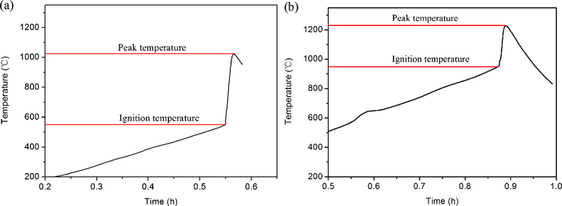
Temperature versus time curves for TiB2/20FeAl under 84 MPa pressure in pseudo-HIP equipment: samples a without and b with preheating treatment
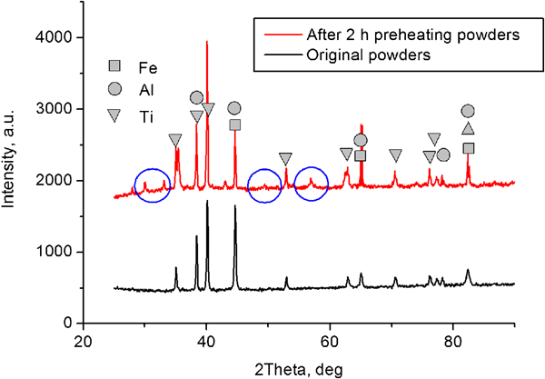
X-ray diffraction results of powder mixtures of TiB2/20FeAl after preheating at 400°C for 2 h in vacuum furnace: there is no boron peak because amorphous boron powder was used
Figure 3 shows the microstructures of TiB2/20Fe3Al after combustion synthesis reaction. As shown in Fig. 3a, the porosity is high for the sample without preheating treatment. In the microstructure of the sample with preheating treatment in Fig. 3b and c, the porosity is decreased. This is probably caused by the following reasons. First, the preheating treatment greatly reduces the impurity adsorbed to the powder surface, such as (water and alcohol), which may form the pore because this kind of impurity is gaseous. Second, as shown in Fig. 1, for the sample with preheating treatment, the peak temperature in pseudo-HIP equipment is high, so under the pressure, the time to keep liquid or semisolid stage will be long, and the steel can be used for placing the compact becoming softer to deform, which may be the reason why many pores can be reduced greatly under pressure. In Fig. 3d, the grey particles are TiB2 (with diameter of ∼ 3 μm), and they are dispersed in the matrix. The dark parts are pores. The preheating process also reduces the TiB2 particle size compared with the hard particles in TiB2/20FeAl material (∼7 μm) without preheating treatment in Ref. 10. The decrease in particle size is probably attributed to the decrease in heat generation during the combustion synthesis reaction and, therefore, the decrease in temperature range (and time region) between ignition and peak temperature. From a view point of industrial use of synthesis reaction products, the TiB2 particle diameter should be small, and the porosity should be low. Thus, the elemental mixture and the compact should be preheated before combustion synthesis so that some SDR can occur between elemental powders during the preheating stage.
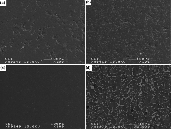
Images (SEI) of TiB2/20Fe3Al samples a without and b, c with preheating treatment: pressure is a, b 84 MPa and c 168 MPa in pseudo-HIP equipment, d the high magnification morphology of c is also provided
The results of relative density are shown in Fig. 4. The Vickers hardness is also shown in this figure. The relative density and the hardness increased greatly when preheating treatment was applied. TiB2/20FeAl has the highest relative density in both cases without and with preheating treatment. The lowest relative density belongs to the TiB2/20Fe composite. The order of hardness of the Fe–Al compounds is as follows: FeAl (509,15 64016) >Fe3Al (353,15 350,16 23517) >Fe (71 HV17). One may expect that the order of hardness of TiB2/Fe–Al composite should follow this order of hardness of binder phase, since the volume fraction of TiB2 is the same. Indeed, this is the case in Fig. 4a. It is also realised in Fig. 4a that the higher the relative density is, the higher the hardness is. In Fig. 4b, the hardness of TiB2/20Fe is not much different from that of TiB2/20Fe3Al. This should be because the relative density of TiB2/20Fe is slightly higher than that of TiB2/20Fe3Al when preheating treatment is applied.
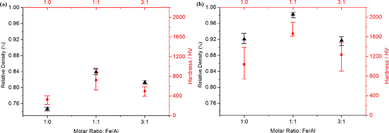
Relative density (dark triangle) and hardness (red quadrangle) for each sample a without and b with preheating treatment: pressure is 84 MPa in pseudo-HIP equipment
Figure 5 shows the effects of pressure and preheating treatment on relative density and hardness. The TiB2/20Fe3Al material fabricated under 168 MPa in pseudo-HIP equipment has a high hardness of 1602 HV and a high relative density of 0·97, which are much higher than the sample fabricated under 84 MPa. Therefore, both preheating treatment and high pressure applied during the combustion synthesis have a significant positive effect on the microstructure and hardness property of TiB2/Fe–Al composites.
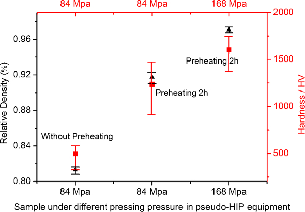
Relative density (dark triangle) and hardness (red quadrangle) of TiB2/20Fe3Al samples under different conditions
Meanwhile, according to the image in Fig. 6, TiB2 phases show a facet character, mainly tetragon and hexagon; one can easily imagine that the shape of TiB2 may be the six-sided prism, because the crystal structure of TiB2 is a kind of layered hexagonal structure with the space group symmetry of P6/mmm. In Ref. 18, the authors proposed that the grains in the hot pressed TiB2 material were preferentially orientated with [0001] direction parallel to the mechanical field. Munro2 reported that the thermal expansion along the a and c axes varied, and Li et al.
19 gave evidence indicating that the compressibility of layered compounds along a and c axes is different. This may lead to anisotropy in mechanical properties. In this work, hard materials containing 80 vol.-%TiB2 were fabricated using the combustion synthesis method. The anisotropy in our case is also of great interest, because the application of this material is cutting or mould parts requiring high isotropy. Therefore, the EBSD analysis of TiB2/20Fe3Al sample was conducted. The obtained crystal orientation map is shown in Fig. 7a, and the [0001],
 and
and
 direction pole figures are shown in Fig. 7b. Both the crystal orientation map and the pole figures clearly show that the TiB2 grains have no preferential orientation. The XRD results of the surface parallel and vertical to the pressing direction in the TiB2/20Fe3Al sample are shown in Fig. 8. The reference pattern is also shown for comparison. Preferential orientation in the TiB2/20Fe3Al material can hardly be seen by comparing the diffractograms from the surface parallel and vertical to the pressing direction. This result is similar to the early work20 that fabricated TiB2–20%MoSi2 composite using hot pressing method, and they reported that the TiB2–20%MoSi2 material has not any preferential orientation after hot pressing process. In our case, the materials without any preferential orientation grains should originate from the independent nucleation of TiB2 particles in the liquid of the Fe–Al–Ti–B system. This isotropy should benefit the mechanical properties for its application as cutter tool or mould.
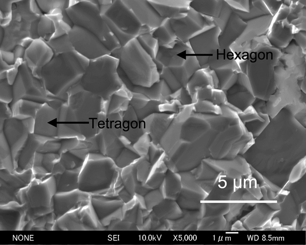
Fracture surface image of TiB2/20Fe3Al sample with preheating treatment: pressure is 168 MPa in pseudo-HIP equipment
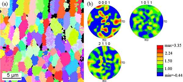
a crystal orientation map and b pole figures of surface vertical to pressing direction in TiB2/20Fe3Al material with preheating treatment: pressure is 168 MPa in pseudo-HIP equipment
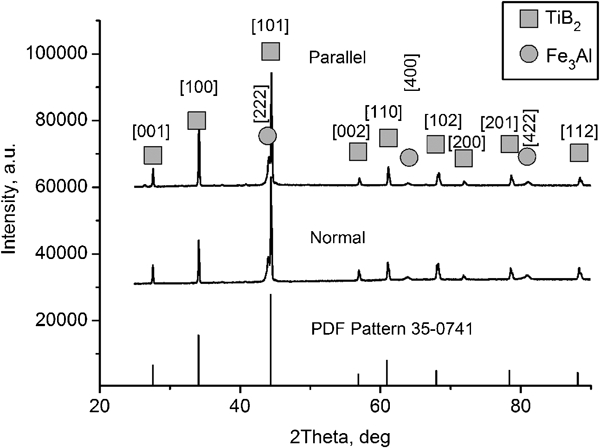
X-ray diffraction results of surface parallel and vertical to pressing direction in TiB2/20Fe3Al material with preheating treatment: pressure is 168 MPa in pseudo-HIP equipment
Figure 9 shows the XRD results of combustion synthesis samples with preheating treatment, and the pressure is 168 MPa in pseudo-HIP equipment. The peaks of TiB2 phase were clearly detected in the TiB2/20Fe3Al, TiB2/20FeAl and TiB2/20Fe materials. However, the peaks of Fe–Al phases were not clear, which should be not only because the amount of Fe–Al compounds was too small to be detected but also because the location of three strongest peaks for Fe3Al (peak locations 44·19, 64·26 and 81·29°), FeAl (33-0020; 44·19, 64·32 and 81·34°) and Fe (06-0696; 44·67, 65·02 and 82·34°) phases is similar. Thereafter, we took TiB2/20Fe3Al for example and measured the element contents of the two phases based on Fig. 10 by electron probe microanalyser, and the results were shown in Table 1. It can be discerned that the grey particles are TiB2 phase, while the white matrix should be Fe3Al compounds mixed with iron. The results indicate that a reaction expressed by equation (1) occurred

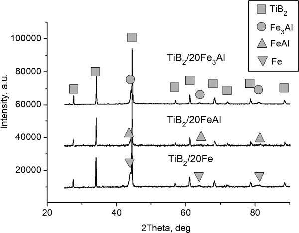
X-ray diffraction results of combustion synthesis samples with preheating treatment. Pressure is 168 MPa in pseudo-HIP equipment. Three spectra seem similar because location of three strongest peaks for Fe3Al, FeAl and Fe in patterns is similar
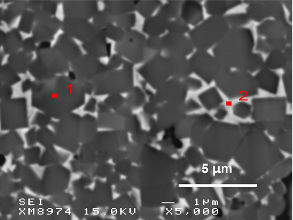
Image (SEI) of TiB2/20Fe3Al material with preheating treatment: pressure is 168 MPa in pseudo-HIP equipment
Electron probe microanalyser analysis results of points in Fig. 10 (at.-%)
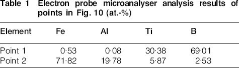
Table 2 shows the results of three-point bending test. The bending strength for all TiB2/Fe–Al materials is ∼650 MPa. Hence, the difference in the binder does not lead to a significant difference in the bending strength. All these composite samples have a much larger bending strength value than the typical TiB2 material (30025 and 350 MPa26) but lower than the Fe–Al binder material, as specified in Table 2. Figure 11 shows the fracture surface of the TiB2/Fe3Al specimen after the bending test. It is well known that the facture mode of TiB2 is a kind of intergranular fracture, while the facture mode of iron aluminides is a mixed intergranular/cleavage fracture.27 In our case, these specimens exhibited mainly intergranular failure and a certain amount of ductile mode. Based on the XRD results in Fig. 9, the intermetallic Fe–Al mixtures probably are Fe3Al compound mixed with iron, which may be the reason for the ductile fracture morphology in Fig. 11. All in all, the TiB2/Fe–Al composites prepared using pseudo-HIP method can have high hardness of above 1600 HV and bending strength of ∼650 MPa.
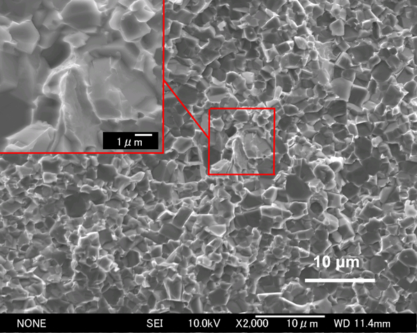
Image (SEM) of fracture surface of TiB2/20Fe3Al sample with preheating treatment: pressure is 168 MPa in pseudo-HIP equipment
Three-point bending strength (σf) for each sample with preheating treatment: pressure is 168 MPa in pseudo-HIP equipment, MPa
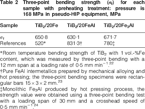
*Room temperature bending strength of TiB2 with 1 vol.-%Fe content, which was measured by three-point bending with a 12 mm span at a loading rate of 0·5 mm min−1.22
†Pure FeAl intermetallics prepared by mechanical alloying and hot pressing; the three-point bending specimens were rectangular bars 15×3×2 mm.23
‡Monolithic Fe3Al produced by hot pressing process, the strength value were obtained using a three-point bending test with a loading span of 30 mm and a crosshead speed of 0·5 mm min−1.24
Conclusions
TiB2 based hard material has been fabricated by combustion synthesis from elemental powders using Fe–Al intermetallics as binder phase. After preheating treatment, the ignition temperature was raised significantly from 560 to 950°C because some slow SDR between elemental powders occurred. Both the crystal orientation map and the pole figures by EBSD analysis clearly show that the TiB2 particles have not any preferential orientation. This may be beneficial for the mechanical properties in the application as cutter or mould. Preheating treatment is helpful for reducing the porosity and the particle size. As the relative density increases, the hardness increases. High pressure applied during the combustion synthesis also has a significant positive effect on the microstructure and hardness property of TiB2/Fe–Al composites. TiB2/Fe–Al composites exhibit mainly intergranular failure, and a certain amount of ductile mode, and have bending strength of ∼650 MPa.