
Abstract
Despite considerable advances in co-sputtering deposition process optimisation, there is rather limited work reported on the effects of process variables on the final deposit characteristics. This article considers the effects of process parameters on the deposition of Al–Cu–Fe quasi-crystalline coatings on silicon (100) substrates. A magnetron co-sputtering system was used to produce a series of deposits. The process variables of parameters, such as sputtering powers and annealing temperatures and times, are correlated and discussed. Scanning electron microscopy, atomic force microscopy and X-ray diffraction are used to analyse the deposited coatings in terms of elemental composition and structure characteristics in the deposition. Sputtering powers are found to be a vital parameter in determining the surface roughness and the maximum grain width of the coatings. An inverse relation between the annealing temperatures and the phase transformations of the β and i phases is observed.
Introduction
Al–Cu–Fe quasi-crystalline materials (QCs) have attracted a great deal of attention in recent years because of its variety of applications. Even though quasi-crystals are mostly metallic alloys, they exhibit low thermal conductivity, electrical conductivity (typical of semiconductors), remarkable tribological behaviour and good resistance to corrosion.1 – 3 It could be considered as mirrors or filters with very good resistance to abrasive wear and because of very low adhesiveness for use in components.
The QCs are also known to be promising candidates for use as functional coating due to their properties, such as high hardness, high Young's modulus, high wear resistance, low friction coefficient, superplasticity at elevated temperatures and thermal expansion coefficients comparable with those of metals.4 – 8
However, the mechanism of QC phase in such materials is strongly dependent on the composition and surface energy because of its complex components and low stability. At the same time, the change in QC grain size essentially affects their physical properties. In this case, the control of process is important for the industrial application of QC Al–Cu–Fe materials; currently, there is a lack of information in the literature regarding the systematic investigation.
Here, a sputter deposited process can be developed as a cost effective approach for the synthesis of Al–Cu–Fe coatings. Sputter deposition is a novel technique for the synthesis of advanced materials. 9 9,10 In this technique, the coatings can be prepared on large area substrates and controlled over the composition. The structures and physical properties of coatings were highly influenced by the deposition parameters, such as the annealing temperature and time, the annealing ambience and the sputtering power.
In this article, the synthesis and structural evolution of Al–Cu–Fe QC coatings using different deposition methods and annealing processes were investigated.
Experimental
Coatings of Al–Cu–Fe were prepared on Si (100) substrates using dc magnetron co-sputtering from a homemade circular planar magnetron sputtering system. The sputtering powers of aluminium, copper and iron targets were controlled at various sputtering powers (Al/Cu/Fe) of 113/18/44 W, 113/13/44 W and 113/13/35 W. The deposition chamber's base pressure was 8··0×10−5 Pa, and during deposition, the gas pressure was 1··0 Pa, and the flowrate of argon gas was set at 5··0×10−7 m3 s−1. The substrate to target distance was 140 mm. Deposition was performed at a substrate temperature of 25°C for 180 min. In this study, the samples were annealed at different temperatures and times (room temperature, 550°C for 5 h and 750°C for 10 h).
The surface morphology was examined by means of atomic force microscopy (AFM, DI Nano-scope IIIA Multimode). The AFM image analysis was carried out using commercial WSxM 4··0 (Nanotec Electronica) software procedures to determine the surface roughness characterised by the root mean square parameter. In addition, the values of average grain size were measured by number counting method over a series of grains associated with a line in the two-dimensional AFM image in the area of 1000×1000 nm. The X-ray diffraction with Cu target (Rigaku D/MAX2550) was used to determine the structure of the coatings. The chemical composition of the coatings was analysed by scanning electron microscopy (JSM-6360LV) with energy dispersive X-ray spectroscopy (EDAX-Falcon).
Results
Figure 1 shows the X-ray diffraction patterns of coatings (113/18/44 W) as a function of annealing temperatures and times. None of the annealing processes showed broadening of peaks, in which the structure is found to be amorphous. Increasing annealing temperatures and times caused the appearance in structure of λ-Al13Fe4 phase to 550°C, β-Al5 (Cu, Fe)5 and ω-Al7Cu2Fe phase to 750°C, as shown in Fig. 1. This indicates that in the annealing process, the energy supplied was sufficient to convert the Fe atoms to its 3+ oxidation state and results in phase formation.11
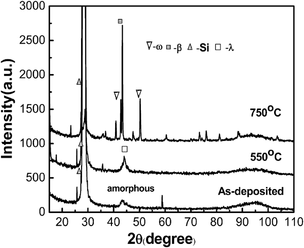
X-ray diffraction patterns of Al–Cu–Fe coatings deposited at sputtering power (113/18/44 W)
The variation of the crystal phase of the Al–Cu–Fe coatings as the decrease in Cu power is shown in Fig. 2. None of the annealing processes showed λ-Al13Fe4 phase grown from the amorphous structure. Increasing annealing temperatures up to 550°C showed a clear phase change from the λ-Al13Fe4 phase to the ω-Al7Cu2Fe and β-Al5 (Cu,Fe)5 phases. It is indicated that the decrease in the power of the Cu target can reduce the reaction temperature of the ω and β phases in the coatings. These results show that high crystallinity can be obtained at high sputtering power ratios (Al/Cu and Fe/Cu) due to the surface diffusion of these atoms (Al and Fe) and, consequently, to the addition of surface mobility of the atoms on the substrate surface.12
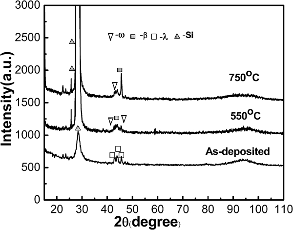
X-ray diffraction patterns of Al–Cu–Fe coatings deposited at sputtering power (113/13/44 W)
According to Fig. 3, increasing annealing temperatures up to 550°C showed that θ-Al2Fe and ω-Al7Cu2Fe disappeared completely, which changed into β-Al5 (Cu,Fe)5 and i-Al62Cu26Fe12 phases with the decrease in Fe power from 44 to 35 W. In addition, the λ-Al13Fe4 peaks disappeared with the increase in i-Al62Cu26Fe12 phase at a higher temperature of 750°C, indicating that alloying of Al, Cu and Fe was completed. This result may be due to the fact that the decrease in the power of the Fe target can reduce the reaction temperature of β and i phases in the coatings.
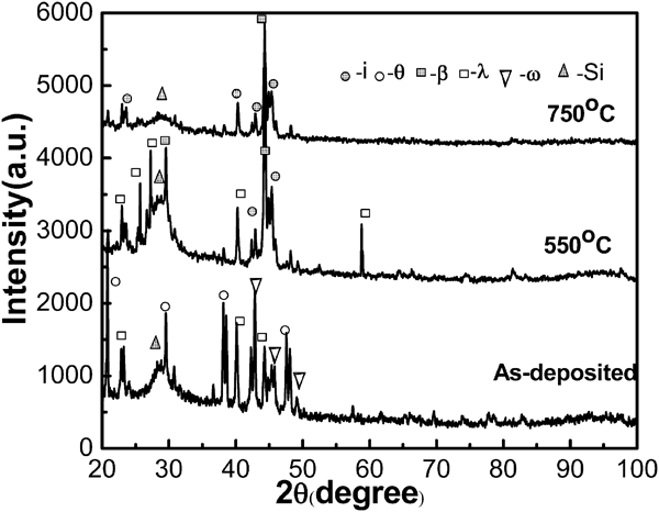
X-ray diffraction patterns of Al–Cu–Fe coatings deposited at sputtering power (113/13/35 W)
Figure 4 shows the AFM images of Al–Cu–Fe coatings prepared at sputtering powers of 113/18/44, 113/13/44 and 113/13/35 W at room temperature, 550 and 750°C annealed respectively. It can be observed that using a higher temperature annealing process can increase the mean surface disturbance and affect the mean area of the coatings. Obviously, the surface roughness decreases with increased annealing temperatures and times. There is an inverse relationship between the mean surface disturbance of the coatings and the phase transformations of β and i phases.13, 14
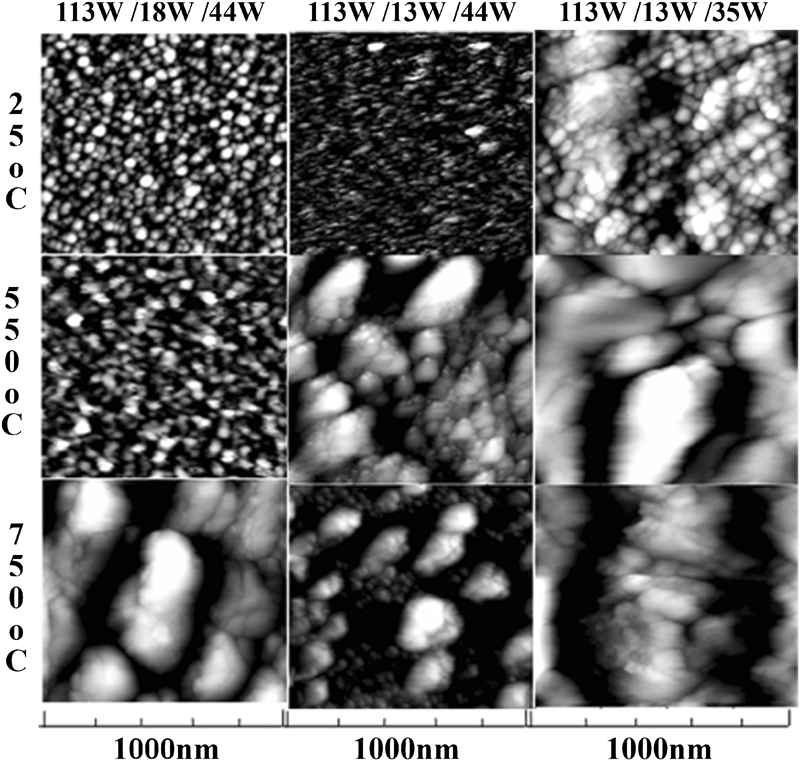
Images (AFM) of Al–Cu–Fe coatings deposited at different powers (113/18/44, 113/13/44 and 113/13/35) for room temperature, 550 and 750°C annealed respectively
At the same time, the change in QC grain size with the decrease in power of Cu and Fe can be found in Fig. 4. It seems that the reduction in Al, Cu and Fe powers may have a significant increase in grain height and width. This means that the control of power processes has a strong effect in changing the composition of the i phase.15 Furthermore, a significant change in the shape and particle size of the QC grain can be observed in Fig. 4, which implies that changing the annealing condition can also control the formation and growth of the QC grain.
Discussion
Phase diagram for Al–Cu–Fe system
The Al–Cu–Fe ternary phase diagram is concluded by energy dispersive X-ray spectroscopy results with various powers (Al, Cu and Fe) annealed at 750°C in Fig. 5. According to the ternary phase diagram for the Al–Cu–Fe system, it is expected that a chemical composition gradient is formed by the application of phase transformation of i-Al62Cu26Fe12 phase in the deposition. The local chemical composition around the ring's outer region changes along the arrow, as seen in Fig. 5, since the atomic ratio (Cu/Fe) of i-Al62Cu26Fe12 is larger than that of Al3CuFe9. In addition, θ-Al2Fe, β-AlFe, β-Al5 (Cu,Fe)5, ω-Al7Cu2Fe and λ-Al13Fe4 phases occurred together, which indicated that these phases come from the solid state reactions reported by Wang et al.16
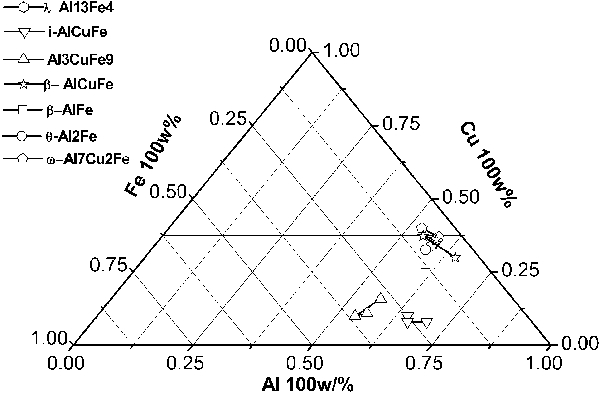
Al–Cu–Fe ternary phase diagram with various powers at 750°C
Possible mechanism for formation of QC phase
It was reported that the majority of ω-Al7Cu2Fe phase with a small amount of i phase and residual β phase was obtained after annealing at 750°C. These solid state reactions occurring in the annealing can be described as follows


Sputtering power is an important parameter that governs particle energy in the coating during the sputtering deposition process. This summarised phase diagram for the Al–Cu–Fe system can be used for accurate structure prediction for any process where phase reaction takes place.
Conclusion
Based on the results from the above experiments, the following conclusions can be drawn.
The crystal structure of the Al–Cu–Fe coatings varied with the decrease in powers, which means that power processes have a strong effect on the phase formation of ω, β and i phases in the coating.
The surface roughness decreases and the QC grain size increases with increased annealing temperatures. This indicates that changing the annealing processes can also control the formation and growth of the QC grain.
The summarised phase diagram for the Al–Cu–Fe system can be used for accurate structure prediction for any process where phase reaction takes place.
Footnotes
Acknowledgements
This work is supported by the Shanghai Specialized Fund for the Outstanding Young Teachers in High Education Institutions (no. gjd11033), the Academic Program of Shanghai Municipal Education Commission (grant nos 11XK11 and 2011X34) and the Innovation Program of Shanghai Municipal Education Commission (no. 10YZ172).