
Abstract
Foundation damping incorporates combined effects of energy loss from waves propagating away from a vibrating foundation (radiation damping) and hysteretic action in supporting soil (material damping). Foundation damping appears in analysis and design guidelines for force- and displacement-based analysis of seismic building response (ASCE-7, ASCE-41), typically in graphical form (without predictive equations). We derive closed-form expressions for foundation damping of a flexible-based single degree-of-freedom oscillator from first principles. The expressions are modular in that structure and foundation stiffness terms, along with radiation and hysteretic damping ratios, appear as variables. Assumptions inherent to our derivation have been employed previously, but the present results are differentiated by: (1) the modular nature of the expressions; (2) clearly articulated differences regarding alternate bases for the derivations and their effects on computed damping; and (3) completeness of the derivations. Resulting expressions indicate well-known dependencies of foundation damping on soil-to-structure stiffness ratio, structure aspect ratio, and soil damping. We recommend a preferred expression based on the relative rigor of its derivation.
Introduction
Following early work by Parmelee (1967), foundation damping as a distinct component of structural system damping was introduced as part of Bielak's (1971) derivation of the replacement (flexible-base) single-degree-of-freedom (SDOF) system and was later refined by Veletsos and Nair (1975), Roesset (1980), and others. The work was predicated on the need to evaluate the effects of soil-structure interaction (SSI) on the seismic response of nuclear power plant reactor containment structures, later extended to buildings and similar systems with more significant higher mode effects (e.g., Crouse and McGuire 2001). Based on that need, and following work by Luco and Westmann (1971), alternative sets of equations were developed to predict foundation damping of a rigid circular foundation resting on a uniform elastic halfspace.
Due in part to the convenience of its application in evaluating seismic demands, foundation damping appears in several seismic design guidelines for buildings (e.g., ASCE-7, ASCE-41, NIST 2012). In both force-based procedures (ASCE-7) and displacement-based procedures (ASCE-41), foundation damping affects the damping ratio used to compute ordinates on the pseudo-spectral acceleration spectrum representing seismic demands. Early versions of ASCE-7 and ASCE-41 utilized graphical solutions for foundation damping that required specific assumptions of foundation geometry; this has been replaced with equation-based methods that appeared first in NIST (2012). We developed the expressions in the NIST report, which are derived, extended, and more fully explained only in this manuscript. Further details on the effects of foundation damping within seismic design guidelines are given in NIST (2012) and online Appendix A of this article.
The principal objective of this paper is to present derivations of foundation damping based on alternative approaches for matching the response of a SDOF equivalent fixed-base oscillator with that of an oscillator founded on a compliant medium. Unlike some prior models, our equations are not specific to particular impedance function equations, but rather are modular in the sense that any appropriate set of impedance functions (analytically or numerically-derived) can be utilized (Modularity in this work implies a system constructed of standard components). Our results show some differences from classical solutions, which we re-derive using the underlying assumptions inherent to those models and express in a similarly modular form. Important distinctions between the current and prior models are related to the present use of a generalized damping formulation that allows for both hysteretic and viscous components, increased transparency regarding assumptions made in the derivation and their effects, and the aforementioned modular nature of the resulting equations. This modularity allows the functions to be readily adapted for various practical conditions not considered in classical solutions such as arbitrary foundation shapes, embedded foundations, and non-uniform soil conditions.
Following this introduction, we present notation related to impedance and oscillators that are used to develop the theory; derive modular equations for foundation damping based on alternate approaches for the matching of flexible-base oscillator response to an equivalent fixed-base response; and compare our results to solutions derived in accordance with classical models from the literature. We conclude with an example and recommendations on the use of the derived equations in engineering practice. Two appendices to this manuscript explain the use of foundation damping in seismic design guidelines and describe the significance of using a generalized damping formulation (as employed here) versus perfectly viscous damping (employed in classical solutions).
Problem Definition and Notation
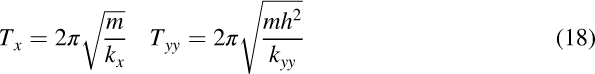
The concept of foundation damping arises from the analogy of a SDOF oscillator of mass m, height h, stiffness k~, period T~, and adjusted damping ratio β0 (Figure 1a), which replaces an otherwise similar oscillator with structural stiffness k = m(2π/T)2 and damping β i that is supported by translational and rotational springs (Figure 1b). Period T and damping β i are oscillator properties for fixed-base conditions in which the base springs have infinite stiffness.
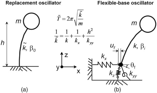
(a) Replacement oscillator used to represent flexible-base system, having stiffness k~. (b) Flexible-base system with horizontal, vertical, and rotational foundation springs (k x , k z , and k yy , respectively) having deflections of u f (horizontal) and Θ f (rotation)—the structural elements have stiffness and damping of k and β i , respectively. Both systems have identical fundamental-mode lateral periods of T~ and damping of β0.
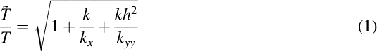
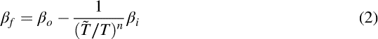
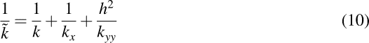
The distinction between fixed- and flexible-base oscillator properties are evaluated from period lengthening (T~/T) and foundation damping (β
f
) as follows (Veletsos and Meek, 1974):
Whereas the analysis of period lengthening is relatively straightforward (Equation 1), formulating an analytical solution for foundation damping is more complex, as it requires assessing the relative contributions of hysteretic and radiation damping in multiple modes of foundation vibration. Essential to this process is the parameterization of foundation stiffness and damping using complex-valued impedance functions (k¯
j
), for which we adopt the following notation (consistent with NIST 2012):

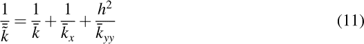
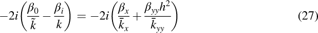
An alternative form for Equation 3 is:


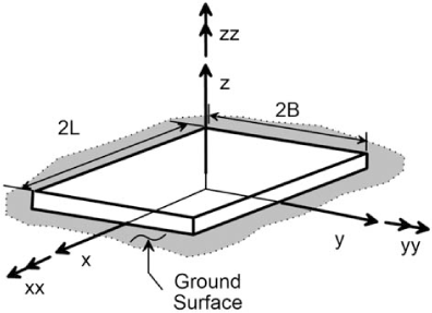
Geometry of rectangular foundations adopted for impedance function equations (L ≥ B).
Approximate impedance equations for rigid circular foundations resting on a visco-elastic halfspace were presented by Veletsos and Verbic (1973), which were based on earlier solutions by Veletsos and Wei (1971). Solutions for rectangular foundations by Pais and Kausel (1988) and Mylonakis et al. (2006) form the basis for recommendations presented in Tables 2.2 to 2.3 in NIST (2012). The modular nature of the foundation damping solutions in this paper allow these or any other impedance solutions to be used to represent soil-foundation interaction.
The formulation of the foundation impedance in Equations 3 to 8 does not explicitly include coupling terms between translational and rotational vibration modes, which are important for embedded foundations (e.g., Assimaki and Gazetas 2009). However, the present formulation without coupling terms can be readily adapted to embedded foundations through the use of an eccentricity (computed from the ratio of coupling/translational stiffness) that is added to the structural height, as described by Maravas et al. (2014).
Foundation Damping Derivations
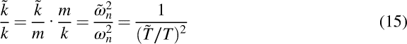
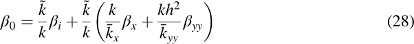
As shown in Figure 1, the stiffness of the replacement oscillator k~ can be related to the stiffness of the individual components of the SSI system as:
We present two approaches for using Equation 11 to derive expressions for foundation damping. The first approach, which is similar in some respects to prior work by Bielak (1971), Roesset (1980), and Wolf (1985), separates Equation 11 into its real and complex parts, then operates exclusively on the imaginary part to evaluate the effective damping of the replacement oscillator. The foundation damping is then readily derived from the system damping. The second approach, which is similar in some respect to prior work by Veletsos and Nair (1975) and Maravas et al. (2014), retains both the real and complex parts of Equation 11 in the evaluation of the dynamic properties of the replacement oscillator. Subsequent sections describe differences between foundation damping derived from the two approaches and compare the present solutions to prior results.
Derivation from Imaginary Component
The first approach proceeds from Equation 11 by expanding each complex stiffness term according to Equation 4:

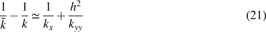
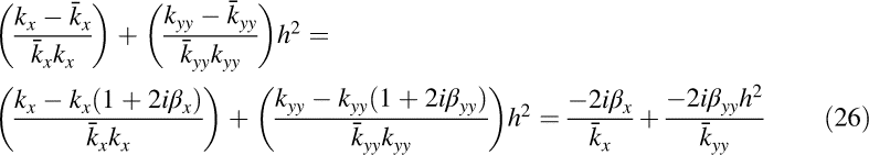
Note that hysteretic soil damping effects are not considered at this stage, but are accounted for subsequently. Multiplying and dividing each term by its complex conjugate, neglecting the higher-order damping terms (i.e., β2 ∼ 0), and multiplying both sides by k, we obtain:


Equation 16 was developed based on the general impedance functions (Equation 3–4) that consider the damping terms to be non-viscous. Frequency-independent (i.e., hysteretic) soil damping (β
s
) can be included in the system by simply adding it to the translational and rotational damping terms (Roesset 1980, Wolf 1985). When applied to the damping formulation in Equation 16, and upon rearrangement, we obtain:


The advantage of Equations 19 and 20 over earlier formulations lies in the nature of the dimensionless multipliers of damping terms, which can be interpreted as weight factors. The sum of the two factors multiplying β i and β s terms is unity. Equation 20 was developed by the authors for NIST (2012), although the derivation appears here for the first time. Previous solutions developed using a comparable set of assumptions to those applied here are described further in subsections below detailing the approaches of Bielak (1971), Roesset (1980), and Wolf (1985).
Derivation from Complex-Valued Impedance Expressions
Our second derivation of foundation damping retains the complex-valued form of Equation 11, but enforces equality of both the real and imaginary parts. Equality of the real-valued terms is given in Equation 10. We rearrange Equations 10–11 to isolate foundation stiffnesses on the right side as:
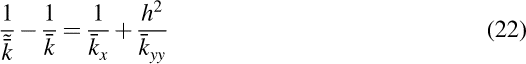


Recalling the relationship between k~/k and (T~/T)2 in Equation 15, we obtain:


Comparison of Alternate Solutions for Foundation Damping
On theoretical grounds, there is no clear preference for one of the aforementioned foundation damping solutions over the other (both were derived using certain approximations, so neither is exact). The two expressions for foundation damping are given in Equations 20 and 34. A practical benefit of the first solution is that it is expressed entirely in terms of real-valued variables, whereas the second includes complex variables that are difficult to understand.
In Figure 3, we plot foundation damping derived from the two solutions against the ratio h/(V S T) (h and T are height and fixed-base period of the SDOF structure in Figure 1, V S is soil shear-wave velocity), which is often called the wave parameter (Veletsos 1977). The wave parameter represents a structure-to-soil stiffness ratio, because h/T quantifies the stiffness of a structure's lateral force resisting system in velocity units whereas V S is related to the soil shear stiffness. For nonlinear problems, the value of V S should be reduced in an equivalent-linear sense (details in NIST 2012). In Figure 3, foundation damping solutions are given for square foundations and various structure height to foundation dimension aspect ratios (h/B) for the case of radiation damping only (Figure 3a) and β s = 0.1 (Figure 3b). Pais and Kausel (1988) fitted impedance functions were used in the calculations. The calculations were performed using a ratio of structure mass to mass of soil in the volume 4B2h of 0.15 (which is a typical value, per Veletsos 1977).
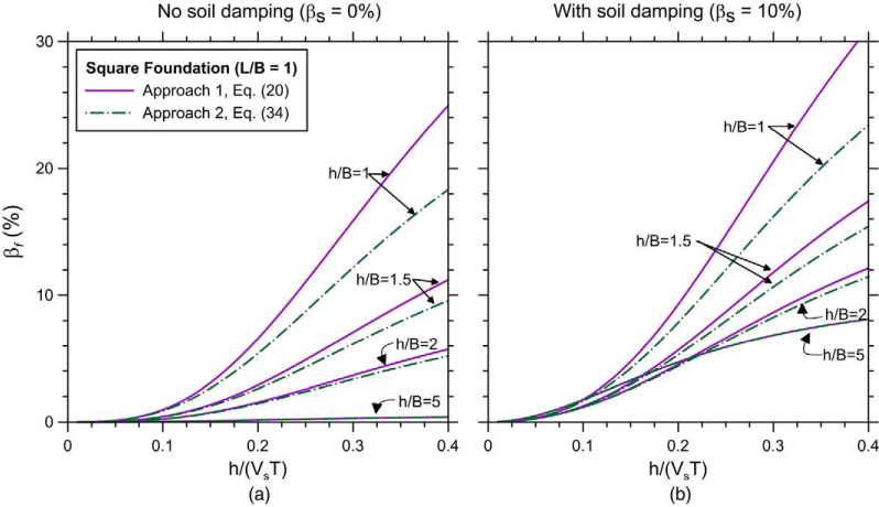
Comparison of foundation damping solutions based on Approaches 1 and 2, plotted against structure-to-soil stiffness ratio h/(V S T) [h/(V S T) = 0 to 0.4 encompasses the range of practical conditions typically encountered for building structures; Stewart et al. 1999]. Conditions for the plots are a rigid, massless, square foundation supported on an homogeneous isotropic halfspace with Poisson's ratio ν = 0.33 and hysteretic soil damping of (a) β s = 0% and (b) β s = 10%. Impedance functions from Pais and Kausel (1988) used to derive the foundation damping. Per text, structure to soil mass ratio is 0.15.
The solution from the first approach produces higher damping, particularly for small h/B ratios. These damping differences result from the dropping of β2 terms in the derivations, the effects of which differ somewhat due to the different assumptions in the two derivations. Otherwise, the solutions show well-known patterns of behavior, in particular:
As h/(V
s
T) increases, the significance of inertial SSI increases, causing increased foundation damping; As h/B increases, rotational modes of foundation vibration become more dominant, which reduces foundation damping because foundation rotation produces less radiation damping than foundation translation; The effects of hysteretic soil damping scale with the significance of inertial SSI, as measured for example by h/(V
s
T). For low h/(V
s
T), hysteretic damping has little effect (zero at h/(V
s
T) = 0), whereas at high h/(V
s
T) the foundation damping is nearly the sum of foundation damping from radiation damping and β
s
.
Comparison to Foundation Damping Solutions in Literature
In this section, we compare results from the expressions derived above to previous solutions for foundation damping of circular foundations by Veletsos and Nair (1975), Bielak (1971), Roesset (1980), Wolf (1985), and Maravas et al. (2014). The original expressions for circular foundations are re-derived here in a more general form.
Bielak (1971) Solution
Bielak (1971; also, Jennings and Bielak 1973 and Bielak 1974) derived an expression for foundation damping by identifying the dynamic properties of a replacement fixed-based oscillator to match those of a flexible-base oscillator (Figure 1b). In the derivation, the foundation mass and mass moment of inertia were taken as negligible (as above), the structural damping was taken as viscous, impedance functions for circular foundations were used, and higher-order damping terms were neglected. The viscous damping assumption for the structure was motivated by computational efficiency.
Bielak's damping derivation is similar to the approach presented in the section entitled Derivation from Imaginary Component in which the imaginary parts of stiffness terms in the replacement oscillator and flexible-base system are equated. The present derivation mirrors the prior one up to Equation 16. However, the assumption of viscous structural damping requires modification of the structural damping ratio as described in online Appendix B (Equation B5–B6). With the substitution of

Veletsos and Nair (1975) Solution
Veletsos and Nair (1975) derived an expression for foundation damping by equating amplitudes of responses between the real parts of the flexible-base system and those of the replacement oscillator. Their derivation utilized the full complex form of stiffness terms in equating the stiffness of the replacement oscillator to that of the flexible-base oscillator, which is similar to the second approach described above in the section entitled Derivation from Complex-Valued Impedance Expressions. The Veletsos and Nair damping terms can be derived using a process matching that used in Approach 2 with two exceptions.
The first exception is that Veletsos and Nair (1975) used viscous structural damping. As in the previous section, in the equation of system damping (e.g. Equation 35), this converts to 3 the exponent on the period lengthening applied to structural damping.
The second exception concerns the incorporation of hysteretic soil damping into the solution. The simple addition of β s to radiation damping terms applied in the derivations for Approaches 1 and 2 represents an approximate solution to the mathematically complex problem of how these damping terms interact. For example, a numerical solution (integral equation approach) to this problem is provided by Apsel and Luco (1987). Veletsos and Nair (1975) use an approximate solution to this problem by Veletsos and Verbic (1973) (the approximation is in the fitting of the dynamic impedance coefficients for the case of zero soil damping with simple closed-form expressions, along with an assumption of real-valued Poisson's ratio). In the Veletsos and Verbic solution, the soil damping appears as a term in a series of equations used to derive dynamic modifiers in the general equations for foundation impedance (α j and β j in Equations 6 and 5, respectively).
These two deviations have little impact on the damping solution from Approach 2, and the derived system damping, given below, is very similar to that in Equation 29:

In Figure 4 we show the effect of the different approaches for incorporating β s into the solution. As a baseline case, we show the predicted foundation damping for β s = 0.1 using Approach 2 (Equation 34). In this calculation, we use radiation damping terms computed from closed-form expressions by Veletsos and Verbic (1973) for the elastic medium (i.e., radiation damping only, or β s = 0). Also shown in Figure 4 is foundation damping from Equation 36 (second term to the right of equal sign), using the same Veletsos and Verbic (1973) impedance solution. The two sets of results are similar, diverging only slightly as h/(V S T) increases for h/r < 5.
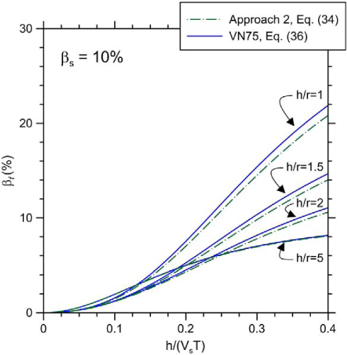
Comparison of foundation damping models (Eq. 34 and Eq. 36) accounting for hysteretic soil damping differently, plotted against structure-to-soil stiffness ratio h/(V S T). Conditions for the plot are a rigid, massless, circular disc supported on an elastic homogeneous isotropic halfspace with hysteretic soil damping β s = 0.1 and ν = 0.33. Impedance functions are from Veletsos and Verbic (1973). Equation 34 used Veletsos and Verbic (1973) elastic impedance solution with additive soil damping; Equation 36 uses similar solution from Veletsos and Nair 1975 (VN75) in which soil damping for a visco-elastic medium is incorporated into the impedance function. Structure to soil mass ratio is 0.15.
Roesset (1980) and Wolf (1985) Solutions
Roesset (1980) presented a foundation damping solution in which the imaginary component of the replacement oscillator stiffness is matched to that of the flexible-base system. He also used a general (non-viscous) damping formulation for the structural stiffness and similar assumptions to other investigators, so the derivation matches that of Approach 1. Using our nomenclature, Roesset's expression for foundation damping was given as:

Wolf (1985) presented a solution that essentially matches that of Roesset (1980), except that the fictitious vibration periods given in Equation 18 are introduced to rewrite the foundation damping in the form given in Equation 20.
Maravas Et Al. (2014) Solution
Recognizing the previous solutions as approximate, Maravas et al. (2014) built upon previous work by Avilés and Pérez-Rocha (1996) to develop an exact solution for damping of rigid circular foundations. The derivation begins with Equation 12, which includes the complex-valued stiffnesses of each element in the SSI system. Multiplying each term by the complex-conjugate, without ignoring the higher-order damping terms, results in:


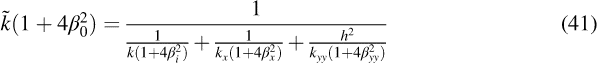

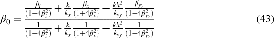
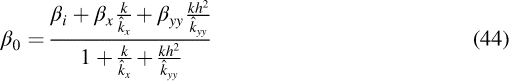
Interestingly, Equations 43 or 44 reduce to Equation 16 if β2 terms are ignored (or if all damping terms are equivalent, which causes k∘ j = k j ). Hence, despite the fact that real and complex parts are included in the derivation, which would seem to make the Maravas et al. (2014) solution conceptually similar to Approach 2, it nonetheless matches the solution from Approach 1 if β2 terms are set to zero or if they are all equal. For this reason, the need to use absolute values in the Approach 2 solution equations is caused by ignoring β2 terms in the derivation. As shown by Givens (2013), foundation damping results obtained using the Maravas et al. (2014) approach are nearly identical to those from Approach 2 over the range of wave parameter h/(V S T) = 0–0.3 (Approach 2 produces slightly larger damping for h/(V S T) > 0.3, as required by the inequality k∘ j > k j ). That similarity suggests that taking the absolute value of the complex-valued impedance terms as in Equation 34 largely compensates for the error associated with ignoring β2 terms in Approach 2.
Although an exact solution such as Equations 43 or 44 could be coded into spreadsheets and applied, we do not recommend it for routine application because (1) its complex form (Equation 43) or unfamiliar nomenclature (e.g. k∘ j terms in Equation 44) convey less clearly the physical sources of foundation damping than do Approaches 1 and 2, and (2) the aforementioned negligible differences from the recommended equations for practical situations (the differences only become appreciable when radiation damping is exceptionally high, such as squat structures on uniform soils subjected to very high frequency excitation, which are rarely encountered conditions).
Summary of Prior Work and Its Relation to Present Results
Both Approaches 1 and 2 for the computation of foundation damping β
f
utilize logical progressions in the derivation processes that have been employed previously, as explained earlier. The main disadvantages of the prior derivations, that we sought to address here, are:
In their originally published form, foundation damping was not expressed in a modular form allowing any impedance formulation to be used, but were connected with equations for the impedance for a particular (usually circular) foundation shape and were available only in graphical form. Accordingly, the present expressions (Equations 20 and 34) are more amenable to practical application. Individual prior studies take one of the fundamental approaches described here, and the similarities and differences of results obtained using alternate approaches are not illustrated. The present approach illustrates directly these differences. The documents presenting the original equations or graphical representations are, in most cases, incomplete with respect to explaining the steps and logic of the derivation process. We derived Equations 20 and 34 from first principles and explained the logic of the solution process.
Example Application
As an example application, we evaluate foundation damping for the Garner Valley, California test site (nees.ucsb.edu/facilities/gvda) using a hypothetical 10 × 50 m surface foundation. Figures 5a–b show the soil shear wave velocity profile (from measurements, as compiled by Star et al. 2015) and foundation geometry. The foundation geometry selected for analysis does not match the dimensions of an actual foundation at the site. The analyzed foundation has a higher aspect ratio (in plan view) for compatibility with plane strain analysis and larger dimensions than actual foundation systems at the site to mobilize responses of relatively deep portions of the profile to enhance effects of soil heterogeneity. Hence, we seek to illustrate through this example how a site-specific impedance function can be employed with the modular foundation damping solutions developed in this paper, and to do so for a case where site-specific complexities in the soil layering would be expected to significantly influence the impedance functions and hence potentially the foundation damping.
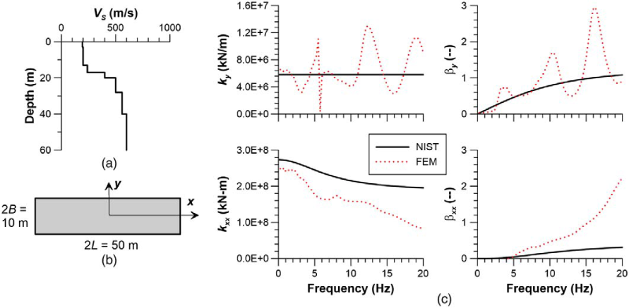
Conditions employed for example computations of foundation damping. (a) V S profile, reflecting actual conditions at the Garner Valley, CA, test site (nees.ucsb.edu/facilities/gvda); (b) plan view of assumed foundation geometry; (c) frequency-dependent foundation stiffnesses for translation (k y ), rotation (k xx ), and associated radiation damping terms (β y and β xx ) for y-component excitation. Foundation stiffness and damping results are shown for finite element simulations using zero soil hysteretic damping (FEM) and Poisson's ratio = 0.45 and from closed form expressions for a soil halfspace adapted to the present conditions following guidelines in NIST (2012).
Using a methodology for plane-strain finite element analysis of foundation-soil systems (Esmaeilzadeh et al. 2016), E. Esmaeilzadeh (pers. comm., 2015) evaluated frequency-dependent and complex-valued impedances for y-component translation and xx-component rotation of the foundation-soil system, with the results shown in Figure 5c. The soil was modelled as elastic (no hysteretic damping) and meshing procedures given in Esmaeilzadeh et al. (2015) were adhered to. The impedance ordinates were obtained from the software by applying unit-amplitude cyclic displacements or rotations, computing the resulting nodal forces on the foundation that develop, and integrating those nodal forces into shear forces and moments at the foundation centroid (which comprise the desired impedance quantities). The plane strain analyses are for excitation in the y-direction; both the real and complex parts were multiplied by 2L to obtain the results in Figure 5c labelled as “FEM.” Radiation damping coefficients were computed from the ratio of complex/real components using Equation 5 (the derivations earlier in this paper were for x-component translation and yy-component rotation, they can be applied to the present case by simply changing subscripts x to y and yy to xx in the equations). Also shown in Figure 5c are stiffness and damping predictions using Pais and Kausel (1988) halfspace equations adapted for non-uniform soil profiles following recommendations in NIST (2012).
Using the impedance ordinates in Figure 5c, we compute foundation damping using Approach 2 (Equation 34) for three fixed-base structure periods (T = 0.1 s, 0.2 s, and 0.4 s), a single structure height h = 5 m (h/B = 1), and excitation in the y-direction. We use a structure mass m of 6.9 × 10⁵ kg (15% of the soil mass in a volume equivalent to the foundation footprint times structure height). The computation process proceeds as follows:
Preliminary estimates of foundation stiffnesses k
y
and k
xx
are obtained by entering Figure 5c at f = 1/T. Calculations are performed using both sets of impedance ordinates. The lengthened building period T~ is computed using Equation 1. Updated foundation stiffnesses are obtained using f~ = 1/T~. Lengthened period is computed again and the process continues until period lengthening is no longer changing between iterations (usually 2–3 are sufficient). Radiation damping coefficients β
y
and β
xx
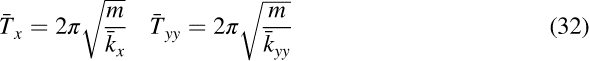
are obtained by entering Figure 5c at f~ = 1/T~. Fictitious periods are computed using Equation 32 with the amplitude of the corresponding complex-valued stiffness from Equation 31 (i.e., for the y-direction, |k¯
y
| is used in the expression for |T¯
y
|). Foundation damping is computed using Equation 34, with the results in Table 1 (the tabulated results are derived from the site-specific impedance ordinates).
Results of example foundation damping computations for site and foundation conditions shown in Figure
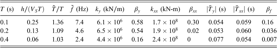
As expected, foundation damping varies strongly with wave parameter h/(V S T), as shown previously in Figures 3 and 4. For comparison, the foundation damping results obtained using the equivalent-halfspace impedance solutions (NIST 2012) are 0.14, 0.038, and 0.007 (for T = 0.1 s, 0.2 s, and 0.4 s, respectively). For these calculations, the equivalent halfspace velocity was taken as 198 m/s based on the ratio of effective depth of influence below foundation (7.5 m) to shear wave travel time as given in NIST (2012). These results are close to those obtained using the site-specific impedance ordinates in Figure 5.
Conclusions
We initially presented the first of our modular equations for foundation damping (from Approach 1) in NIST (2012), to overcome limitations of graphical methods for evaluating foundation damping that appeared in earlier seismic analysis and design guidelines documents (ASCE-7 2010, ASCE-41 2006). Those guidelines have since been updated using our solutions as presented in NIST (2012). In this paper, we have presented the basis for Approach 1 and extended the derivation using a different set of assumptions for matching the real and complex parts of the response of an equivalent fixed-based oscillator to that of a flexible-base oscillator (Approach 2). The underlying assumptions and logic behind Approaches 1 and 2 are not original, but the derivations here have unique and useful elements relative to prior work as explained in the section entitled Summary of Prior Work and its Relation to Present Results.
Given the presence of two sets of equations for foundation damping, a natural question is which solution is preferred for application? As illustrated in Figure 3, the two solutions are not significantly different and other factors (such as the modeling of heterogeneous soil conditions in the impedance) are likely to exert more influence on results than the choice of equations. Nonetheless, our view at the present time is that Approach 2 is preferred, principally because it is more complete in its assessment of the equivalent oscillator response (by considering real and complex parts). The foundation damping from Approach 2 is given by Equation 34 and an example application is given in the previous section. Because the foundation damping expressions are derived to match SDOF oscillator responses, they are applicable strictly to analysis of SSI effects on the first-mode response of structures.
Footnotes
Acknowledgments
This material is based on work supported by the National Science Foundation under Grant No. CMMI-0618804 (P.I. Jack Moehle). Any opinions, findings, and conclusions or recommendations expressed in this publication are those of the authors and do not necessarily reflect the views of the NSF. Support for the second author was provided by the University of Patras as part of a sabbatical leave to UCLA in 2010–2011. We are grateful to Elnaz Esmaeilzadeh Seylabi for computing the impedance ordinates for the example application. We thank the three reviewers of this paper for their helpful input.
Appendices
Please refer to the online version of this article to access the supplementary material in Appendix A and Appendix B.
References
Supplementary Material
Please find the following supplemental material available below.
For Open Access articles published under a Creative Commons License, all supplemental material carries the same license as the article it is associated with.
For non-Open Access articles published, all supplemental material carries a non-exclusive license, and permission requests for re-use of supplemental material or any part of supplemental material shall be sent directly to the copyright owner as specified in the copyright notice associated with the article.