
Abstract
Background: Intramedullary implants are being used with increasing frequency for tibiotalocalcaneal fusion (TTCF). Clinically, the question arises whether intramedullary (IM) nails should have a compression mode to enhance biomechanical stiffness and fusion-site compression. This biomechanical study compared the primary stability of TTCF constructs using compressed and uncompressed retrograde IM nails and a screw technique in a bone model. Methods: For each technique, three composite bone models were used. The implants were a Biomet nail (static locking mode and compressed mode), a T2™ femoral nail (compressed mode); a prototype IM nail 1 (PT1, compressed mode), a prototype IM nail 2 (PT2, dynamic locking mode and compressed mode), and a three-screw construct. The compressed contact surface of each construct was measured with pressure-sensitive film and expressed as percent of the available fusion-site area. Stiffness was tested in dorsiflexion and plantarflexion (D/P), varus and valgus (V/V), and internal rotation and external rotation (I/E) (20 load cycles per loading mode). Results: Mean contact surfaces were 84.0 ± 6.0% for the Biomet nail, 84.0 ± 13.0% for the T2 nail, 70.0 ± 7.2% for the PTI nail, and 83.5 ± 5.5% for the compressed PT2 nail. The greatest primary stiffness in D/P was obtained with the compressed PT2, followed by the compressed Biomet nail. The dynamically locked PT2 produced the least primary stiffness. In V/V, PT1 had the (significantly) greatest primary stiffness, followed by the compressed PT2. The statically locked Biomet nail and the dynamically locked PT2 had the least primary stiffness in V/V. In I/E, the compressed PT2 had the greatest primary stiffness, followed by the PT1 and the T2™ nails, which did not differ significantly from each other. The dynamically locked PT2 produced the least primary stiffness. The screw construct's contact surface and stiffness were intermediate. Conclusions: The IM nails with compression used for TTCF produced good contact surfaces and primary stiffness. They were significantly superior in these respects to the uncompressed nails and the screw construct. The large contact surfaces and great primary stiffness provided by the IM nails in a bone model may translate into improved union rates in patients who have TTCF.
Introduction
Many different techniques have been proposed for tibiotalocalcaneal fusion (TTCF). Fixation can be obtained with screws, plates, external fixators, and intramedullary (IM) nails. 3,5 Compression, stable fixation, correct hindfoot alignment, and apposition of well-vascularized bony surfaces resulting in sound bony union with few complications are the main principles of TTCF. 12,21,24
As long ago as 1962, Küntscher 14 described closed retrograde TTCF using unlocked nails. Since then, special IM nails with appropriate locking systems and optional compression options have been devised. Mann et al. 17 reported that a retrograde nail with a posterior-to-anterior interlocking screw passed through the calcaneus in a longitudinal fashion provided significantly more rotational stiffness than the same nail construct using a conventional transverse calcaneal screw. Berson et al. 3 showed fusion-site compression by a nail with an external compression mechanism. It seems reasonable that, similar to the use of compression in other internal fixation techniques for the management of fractures and nonunions, compression exerted by an IM nail would enhance the stability of a fusion construct. The effect of compression on the biomechanical stiffness of TTCF constructs with an IM nail has not been studied to date and is not described in the current biomechanical literature.
We hypothesized that, in TTCF, compressed retrograde IM nails would be superior, in terms of biomechanical primary stiffness, to uncompressed retrograde IM nails and to a three-screw construct.
Material and Methods
The bone model consisted of Sawbones® third-generation composite tibial models and anatomically correct synthetic models of the talus and the calcaneus (Sawbones Europe, Malmö, Sweden). The articular surfaces at the distal tibia and the talar dome were resected with a machine to produce defined plane parallel surfaces. Fusion was performed in neutral flexion, 5 degrees of external rotation, and 5 degrees of hindfoot valgus. The talocalcaneal joints were not resected, since doing so might have led to variations in the bone model.
Three synthetic-bone constructs each were created using the following devices:
a retrograde IM nail, static locking mode (Biomet Ankle Arthrodesis Nail, Biomet, Berlin, Germany)
a retrograde IM nail, compressed mode (Biomet Ankle Arthrodesis Nail, Biomet, Berlin, Germany)
a retrograde IM nail, compressed mode (T2™ Femoral Nail, Stryker, Duisburg, Germany)
a retrograde Prototype 1 IM nail, compressed mode (Stryker, Schönkirchen, Germany)
a retrograde Prototype 2 IM nail, dynamic locking mode (Stryker, Schönkirchen, Germany)
a retrograde Prototype 2 IM nail, compressed mode (Stryker, Schönkirchen, Germany)
a three-screw construct (cannulated screws, Stryker, Duisburg, Germany)
To ensure reproducible implantation of the IM nails through the talus and the calcaneus, a two-part epoxy mold was used for the controlled alignment of these bones. The hole for the IM implant was drilled retrograde through the calcaneus and the talus at defined distances from the edge of the mold. The medullary cavity of the tibia was reamed retrograde to a diameter of 12 mm. The IM nails used in all of the tests were made of a titanium alloy and had a length of 18 cm and a diameter of 11 mm; all the locking screws used were 5 mm in diameter.
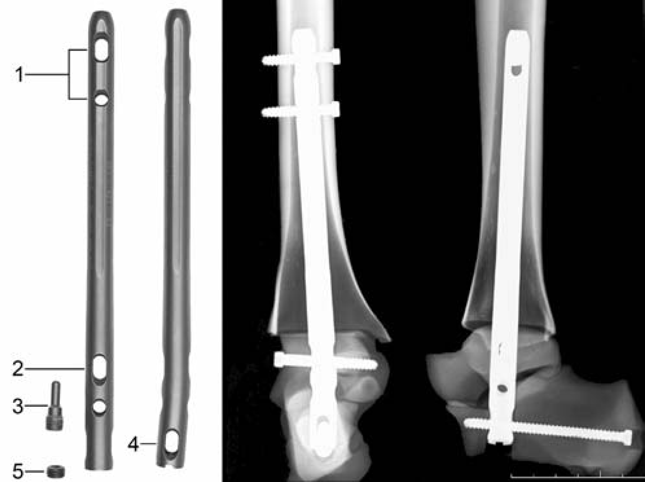
The first device studied was the Biomet nail in static locking and compressed modes. Locking was obtained proximally with two screws in the tibia. For the statically locked mode, a locking screw was inserted distally in the talus, and two such screws were inserted into the calcaneus (Figure 1). For the compressed mode, compression was applied manually through the external compression system before locking at the distal site (Figure 2). As a final step, the locking screws in the talus and the calcaneus were inserted.
The second retrograde TTCF construct using an IM compression nail was a T2™ femoral nail. The device was anchored in the tibia with two locking screws. Distally, the nail was locked with a shaft screw passed through the longitudinal oval hole at the level of the talus; the talus was then compressed against the tibial articular surface using an internal compression screw tightened with a torque of 2 N-m, as recommended by the manufacturer. Finally, the nail was statically locked in the calcaneus, and the locking screw was blocked with an end cap to produce an angle-stable construct (Figure 3).
In addition to these constructs, two prototype retrograde IM compression nails that had been specially developed for this study (Stryker, Schönkirchen, Germany) were tested. Prototype 1 (PT1) had a distal 4-degree angulation intended to replicate the physiologic hindfoot valgus and to provide more stable anchoring in the calcaneus (Figure 4). Fusion-site compression was applied through a longitudinal hole in the nail at the level of the calcaneal locking site. PT1 was locked twice in the tibia and posteroanteriorly into the calcaneus with a shaft screw through the longitudinal hole. Compression was applied with a torque of 2 N-m, and static locking was performed at the talus and with an additional screw at the calcaneus.
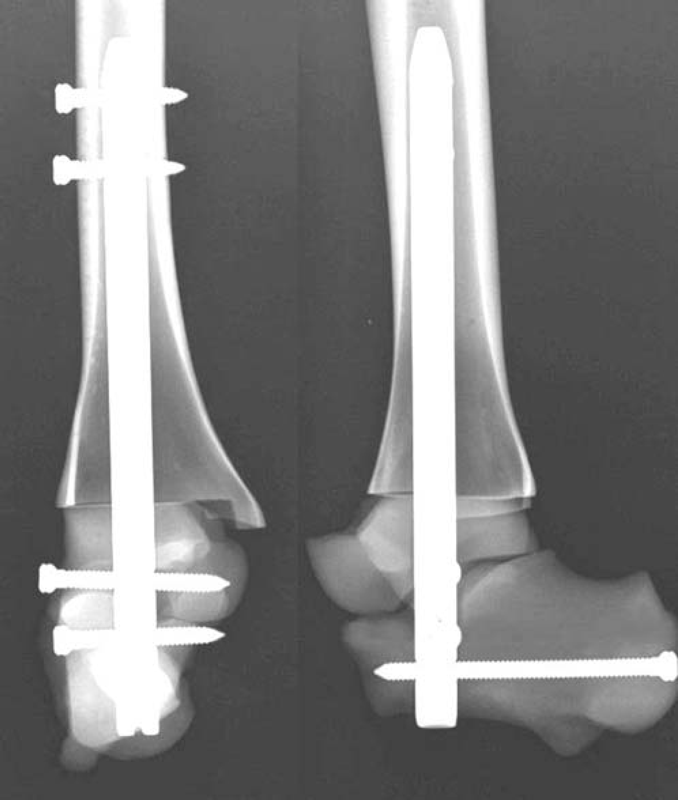
The Biomet ankle arthrodesis nail was used in a static locking and in a compressed mode.
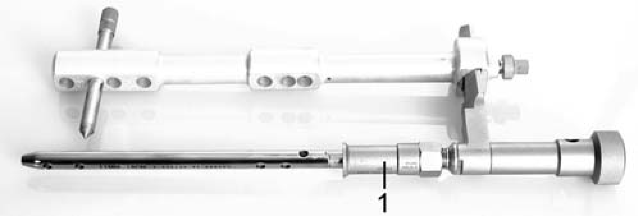
The compression was applied manually through the external compression system (1).
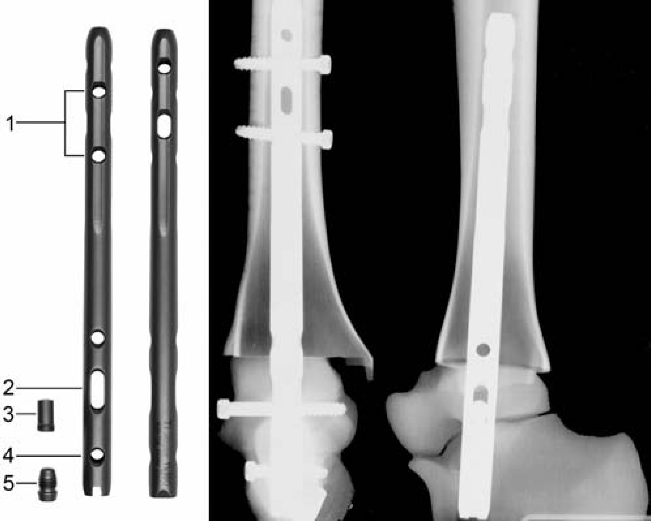
Retrograde femoral nail (T2™): locking screws in the tibia (1), shaft screw passed through the longitudinal hole at the level of the talus (2), compression screw (3), static locking in the calcaneus (4), blocking of the locking screw with an end cap (5).
The next implant tested was Prototype 2 (PT2), which provided dual compression. This prototype, too, had a distal 4-degree valgus angulation. Unlike PT1, it had a dual internal compression mechanism (Figure 5). The design involved two longitudinal holes in the nail, allowing the tibiotalar and the subtalar fusion sites to be compressed separately with compression screws. The nail was anchored in the tibia with two locking screws. In the talus, the nail was locked with a shaft screw, following which the talus was compressed against the tibia with a preloaded compression screw using a torque of 2 N-m. Posteroanterior calcaneal locking was applied, and the second compression screw was used to compress the calcaneus against the talus, using a torque of 2 N-m. In addition to this compressed mode, PT2 also was tested in a dynamic locking mode without compression.
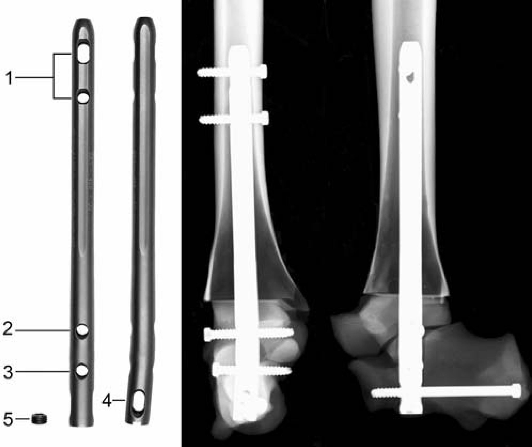
Prototype 1 with distal 4-degree valgus angulation, locked twice in the tibia (1), posteroanteriorly into the calcaneus with a shaft screw through the longitudinal hole (4), compression screw (5), static locking in the calcaneus (3) and talus (2).
The screw TTCF construct was made up of three cannulated 6.5-mm-diameter titanium-alloy screws. The prepared synthetic bones were provisionally fixed with an axial Kirschner wire, and three guide wires for the cannulated screws were inserted under fluoroscopic control. The guide wires were overdrilled with a 4.9-mm-diameter drill bit, and the fusion site was fixed with the three cannulated screws (Figure 6). The screws were tightened with a torque wrench, using a torque of 3 N-m as recommended by the manufacturer. Implant positioning was verified with biplanar radiography.
For each construct, the fusion-site contact-surface area between the talus and the tibia was measured using an adaptation of a technique described by Ogilvie-Harris et al. 20 A pressure-sensitive film (Fujifilm Prescale Pressuregraphe Super-Low, Fuji, Tokyo, Japan), which changes color when pressure is applied, was placed between the articular surfaces of the tibiotalar joint. For the nailed constructs, a circular hole matching the nail diameter was first made in the film. After instrumentation with the intended torque, the film was removed and the outlines of the compressed surface area and of the total available fusion-site area were marked on the film with a permanent marker. The areas were scanned into the computer, and the share of the compressed area in the total available area was assessed with digital image analysis. The cross-sectional area of the fixation device was counted as part of the compressed contact area.
Prototype 2 with distal 4-degree valgus angulation, locked twice in the tibia (1), shaft screw passed through the longitudinal hole at the level of the talus (2), compression screw (3), locking posteroanteriorly into the calcaneus through the longitudinal hole (4), compression screw (5).
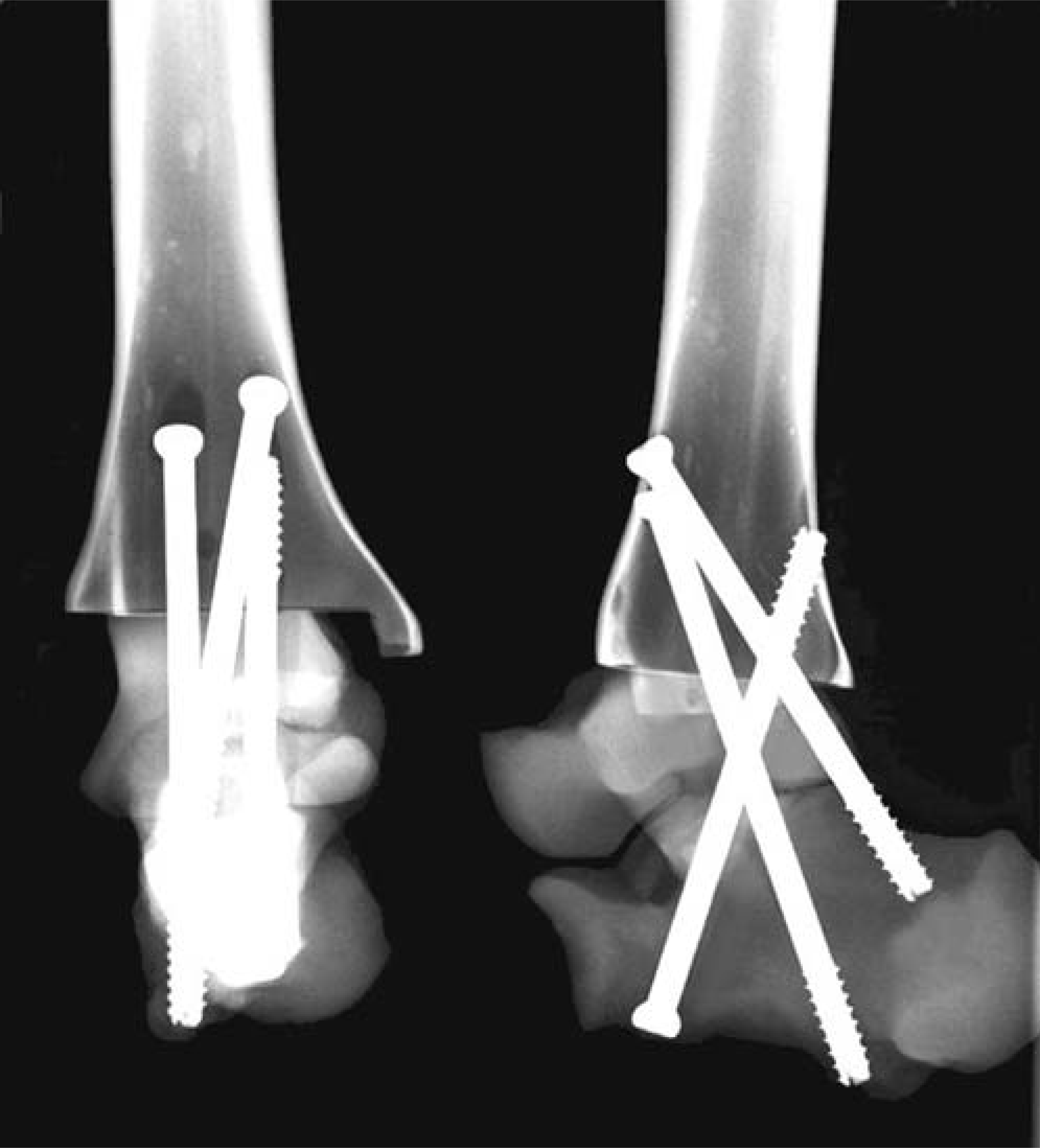
TTCF construct with three cannulated 6.5-mm-diameter screws.
Biomechanical testing of primary stiffness in dorsiflexion/plantar flexion (D/P), varus/valgus (V/V), and internal rotation/external rotation (I/E) was performed on a universal testing machine (Zwicki, Zwick GmbH, Ulm, Germany). The distal part of the calcaneus was placed in an aluminum casing (Industrietechnik und Maschinenbau GmbH, Solingen, Germany) and potted with epoxy resin. Any parts of the implants protruding from the calcaneus were covered with an elastic rubber mass to ensure congruent contact and unrestricted mobility of the implants. The specimen was held in a two-part aluminum and epoxy resin mold with a distal cantilever length of 10 cm (Figure 7).
The testing machine plotted the load-displacement graph for the load at the fusion site. Displacement-controlled loading was applied at a rate of 1-degree per second until a maximal torque of 5 N-m was reached, using a technique similar to that described by Friedman et al. 10 Because of the design of the experimental setup, different lever-arm lengths were required for the different directions tested, resulting in maximal testing-machine loads of 31.25 N for D/P and V/V (lever-arm lengthen 16 cm), and of 38.5 N for I/E (lever-arm length, 13 cm). We used a calibrated 2.0 kN load cell (AST GmbH, Dresden, Germany). The instrumented specimens underwent alternating cyclic loading. The first 20 cycles of each loading mode were analyzed. The first 20 cycles were included to detect potential effects of instrumentation settling. Following loading in a given mode, the instrumented bone models were checked visually for signs of loosening and evidence of plastic deformation. Re-tightening was done using the defined torque. The sequence of tests was (1) in D/P, (2) in V/V, (3) in I/E.
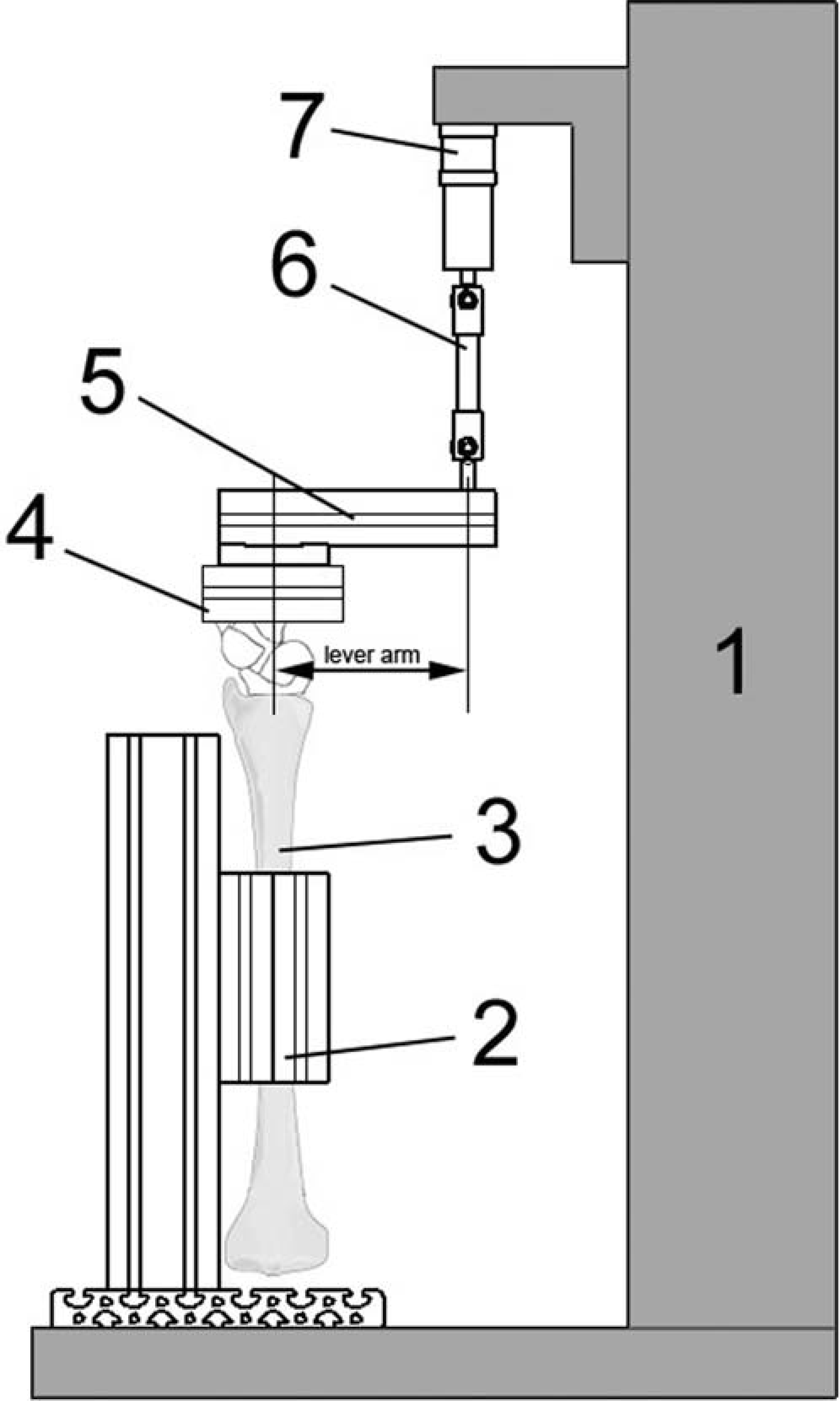
Schematic view of the biomechanical test set-up. Universal testing machine (1) with load cell (7), joint rod (6), and lever arm (5). The distal portion of the calcaneus was placed in an aluminum casing (4). The tibia (3) was mounted with a distal cantilever length of 10 cm. The specimen was held in a two-part aluminum and epoxy resin mold (2).
Using a principle described for biomechanical studies of the spine, 28 the range of motion (ROM) and the neutral zone (NZ) were measured. The ROM was defined as the angulation caused by the maximal torque of 5 N-m. The NZ was defined as the range over which the specimen moved essentially free of applied loading and reflected the play at the fusion site.
The results were analyzed for normal distribution with the Kolmogorov-Smirnov test and the Shapiro-Wilk test; to establish significance, the Mann-Whitney test was used (software: SPSS, Version 11.5). P-values less than 0.05 were considered significant.
Results
In the analysis of the contact surfaces, account was taken only of the compressed IM implants. The three-screw construct would have involved interference with the pressure-sensitive film during screw insertion, which would have adversely affected reproducibility. Contact-surface analysis also was not done in the statically locked constructs, because in these specimens there was no discernible discoloration of the pressure-sensitive films.
The Biomet nail had a mean contact-surface area of 84.0 ± 6.0%; the T2™ femoral nail had a mean area of 84.0 ± 13.0%; PT1, 70.0 ± 7.2%; and PT2, 83.5 ± 5.5% (Figure 8). These differences were not significant.
With D/P testing, the significantly (p < 0.001) greatest primary mechanical stiffness was produced by the dual-compression PT2, followed by the compressed retrograde Biomet nail, which was significantly (p = 0.001) stiffer than PT1 and the retrograde T2™ femoral nail (Figure 8). Compared with the compressed IM nails, the statically locked Biomet nail and the screw construct were significantly (p < 0.05) less stiff. The dynamically locked PT2 had the least primary mechanical stiffness and the largest neutral zone in D/P. In the assessment of the neutral zone with D/P loading, the angular movement free of applied loading of the compressed Biomet nail and the compressed prototypes 1 and 2 was essentially the same as the play of the experimental setup. This suggests that these implants did not have a neutral zone when tested with D/P.
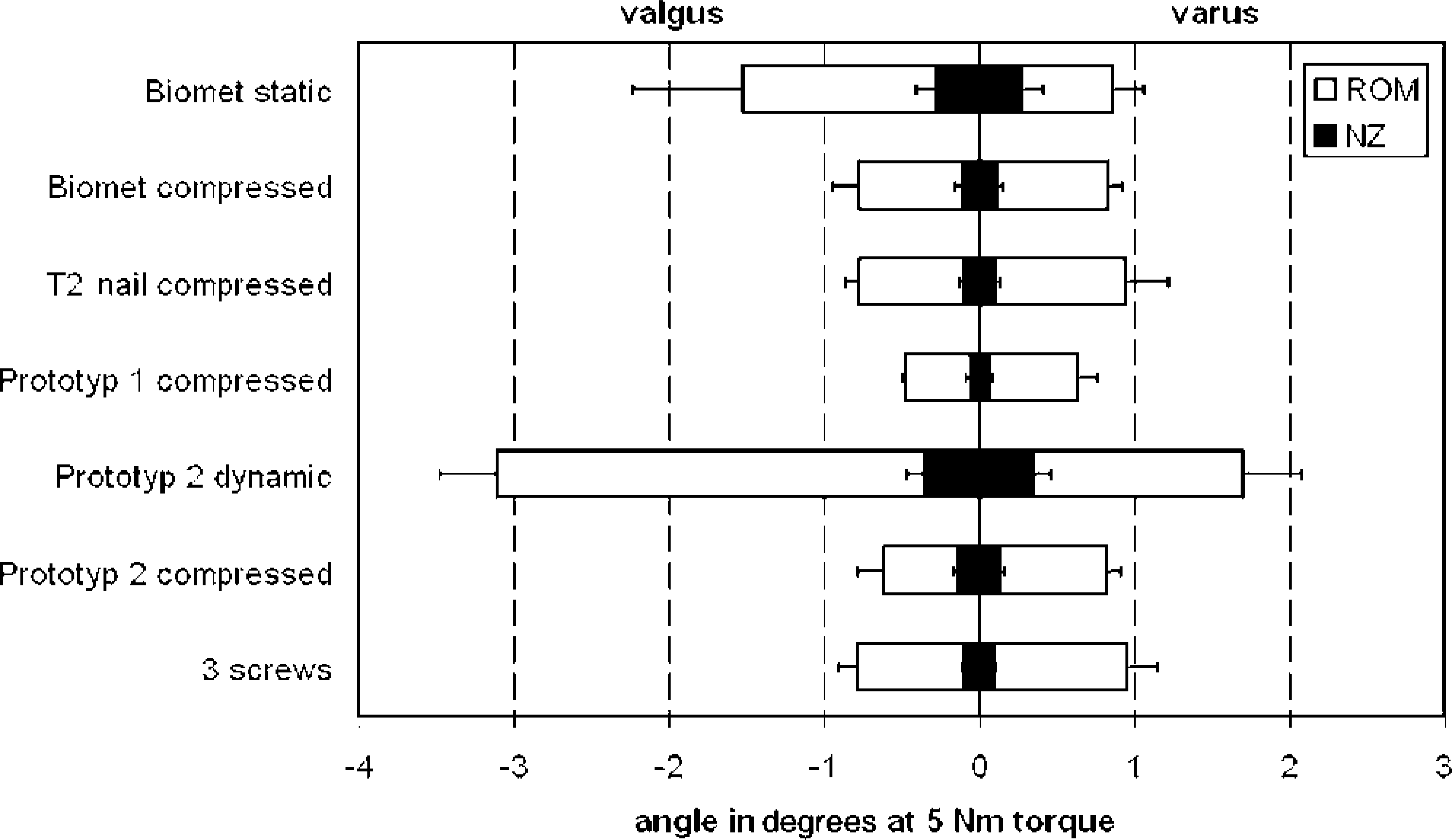
With V/V testing, the significantly (p < 0.001) greatest primary mechanical stiffness was produced by the single-compression retrograde PT1, followed by the dual-compression PT2 (Figure 9). The differences in primary stiffness among the retrograde T2™ femoral nail, the screw construct, and the compressed Biomet nail were not significant. The statically locked Biomet nail and the dynamically locked PT2 produced the least primary mechanical stability. PT1 had the significantly (p < 0.001) smallest NZ, followed by the compressed Biomet nail, the screw construct, and the retrograde T2™ femoral nail, which were not significantly different. The dynamically locked PT2 had the largest NZ.
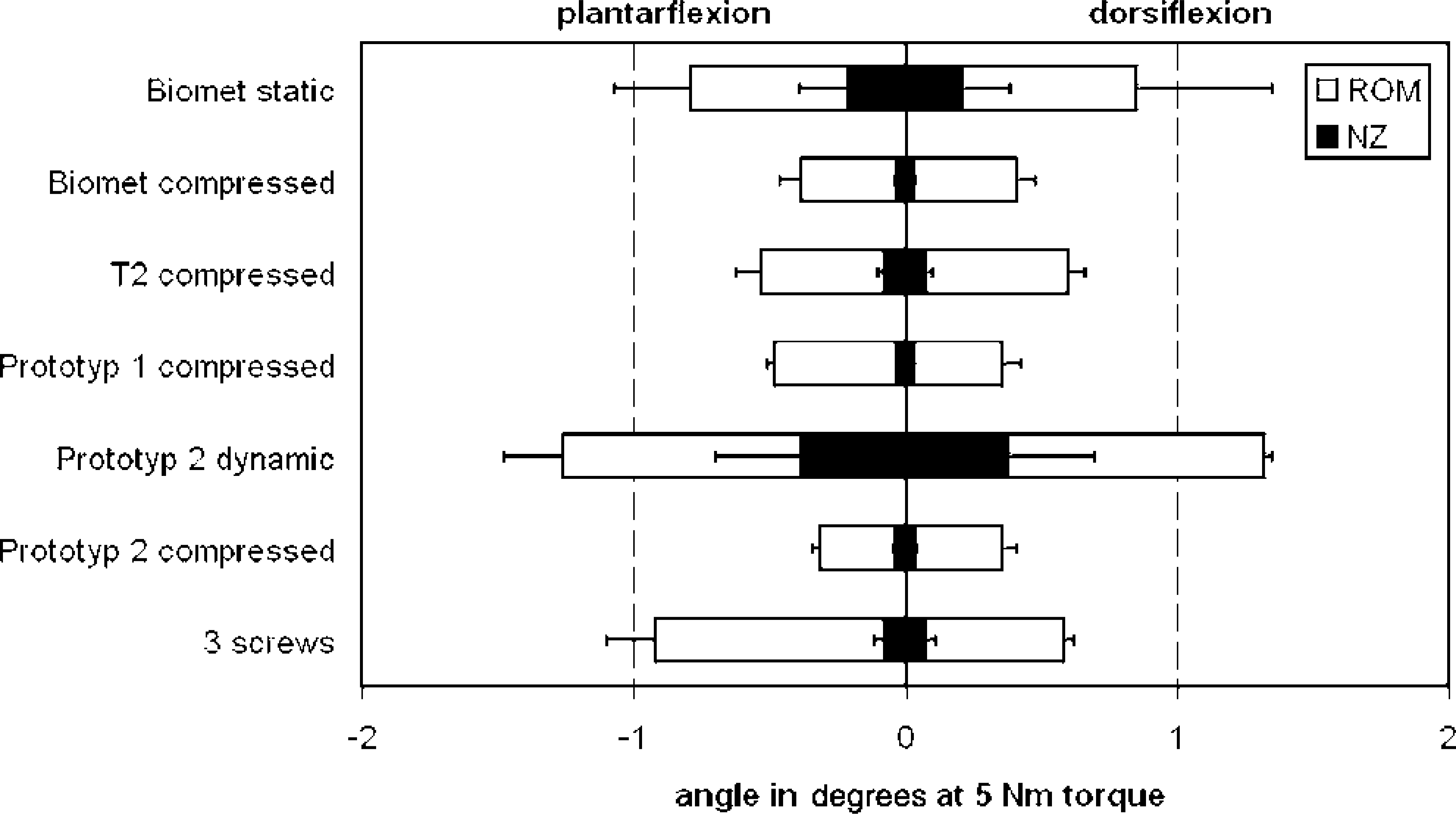
Loading in dorsiflexion/plantarflexion until a maximal torque of 5 N-m was reached. The range of motion (ROM) and the neutral zone (NZ) were measured in degrees. The brackets indicate standard deviation.
Loading in internal rotation/external rotation until a maximal torque of 5 N-m was reached. The range of motion (ROM) and the neutral zone (NZ) were measured in degrees. The brackets indicate standard deviation.
With I/E testing, the dual-compression PT2 produced the significantly (p = 0.002) greatest primary stiffness, followed by PT1 and the retrograde T2™ femoral nail, which did not differ significantly (Figure 10). These implants were followed by the screw construct, which was significantly (p = 0.003) stiffer than the compressed locked Biomet nail. The dynamically locked PT2 had the least primary stiffness when tested with I/E. The smallest NZ was seen in the compressed PT2, followed by the retrograde T2™ femoral nail and PT1. The dynamically locked PT2 was found to have the largest NZ.
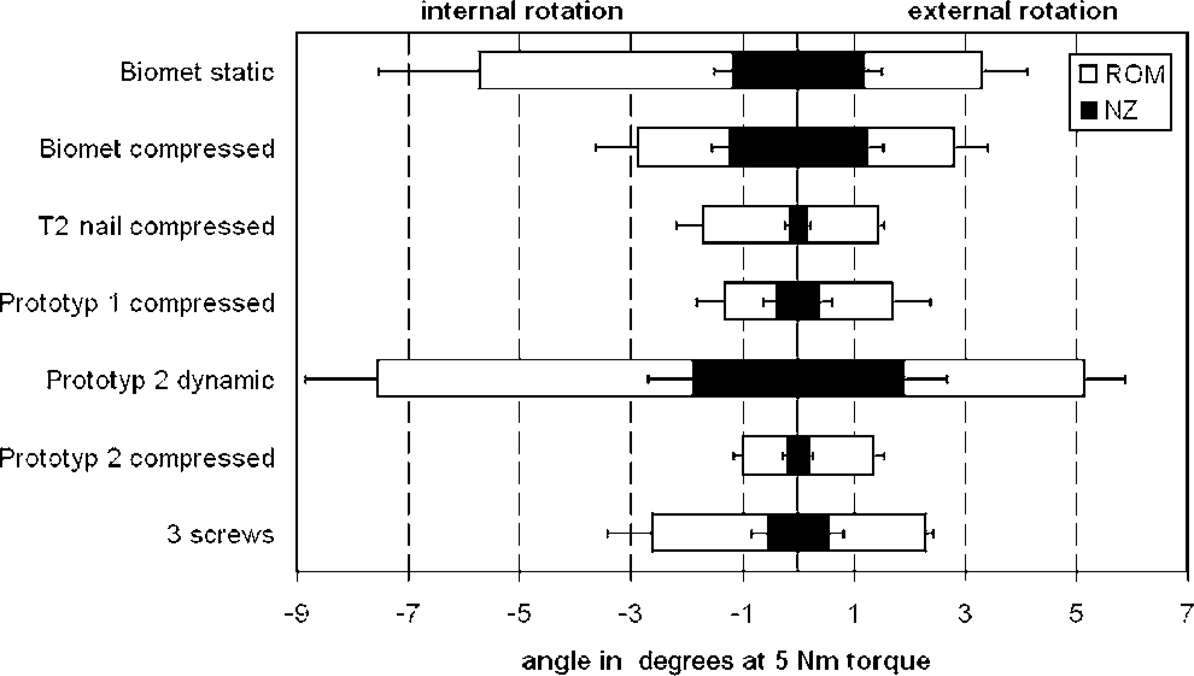
Loading in internal rotation/external rotation until a maximal torque of 5 N-m was reached. The range of motion (ROM) and the neutral zone (NZ) were measured in degrees. The brackets indicate standard deviation.
Discussion
Tibiotalocalcaneal fusion is used in the management of such conditions as advanced osteoarthritis of the ankle and subtalar joints, necrosis of the talus, rheumatoid disease, failed total ankle arthroplasty, and severe hindfoot deformity. Over the past several years, intramedullary implants have been increasingly used, 5,13,15,18,22,23 with good clinical outcomes reported by a number of authors. 11,13,15,18,22,23 The primary benefits cited for IM implants are their potential for percutaneous insertion and the stability of the constructs obtained with these devices. 11,13,16,18,23
Our study compared the primary stiffness provided by five different TTCF implants (four different retrograde IM compression nails, one screw technique) in a synthetic-bone model. Two of the IM devices were tested in both a compressed mode and a statically or a dynamically locked mode. The dual-compression PT2 had significantly superior primary stiffness in D/P and I/E compared to the other implants. Only with V/V loading did the single-compression PT1 significantly outperform PT2. The dynamically locked PT2 had the least primary stiffness and the largest NZ of all loading modes; the statically locked Biomet nail ranked second-worst. In all loading modes, the compressed IM devices produced significantly greater biomechanical stiffness than did the uncompressed implants. In particular, with I/E loading, all the IM nails with an internal compression mechanism (retrograde T2™ femoral nail, PT1, PT2) did significantly better than the IM nail with an external compression mechanism (Biomet nail). Except when tested with D/P loading, the screw construct's stiffness was intermediate between the best of the compressed IM nails (PT1 and compressed PT2) and the uncompressed nails (static-mode Biomet nail, dynamic-mode PT2). In the D/P loading test, the screw construct was equal to the statically locked Biomet nail.
Our testing setup was comparable to similar systems used in other biomechanical studies. As other authors, 19 we modeled our experiment on the study by Friedman et al. 10 Because our study involved a comparison within the elastic range, no higher torques were required. Given the synthetic-bone model chosen, there appeared to be no need for testing to destruction.
Two earlier biomechanical studies 2,9 involved in-vitro comparisons of the stiffness of retrograde interlocked IM nails and screw constructs in TTCF. In a human cadaver bone model, Berend et al. 2 found that a 15-cm-long IM nail provided greater stiffness in all directions tested when compared with two crossed lag screws. The IM nail was locked in the talus and the calcaneus and was manually impacted to achieve compression across the fusion sites. Finally, the nail was locked in the tibia. These authors, too, used a setup as described by Friedman et al. 10 Fleming et al. 9 compared a TTCF construct using an uncompressed retrograde 32-cm-long femoral rod and three crossed screws and found the nailed construct to be stiffer by a factor of 1.5 to 2.73, in all directions tested. It should, however, be noted that only one of the three cannulated screws used in that study was passed through the tibiotalocalcaneal joints; the other two screws had been inserted merely to stabilize the tibiotalar and the talocalcaneal joints.
The finding in our study that the screw construct was significantly stiffer than the uncompressed statically-locked nail (static-mode Biomet) in V/V and in I/E testing may be accounted for by the use of a third screw for joint fusion. Also, both Berend et al. 2 and Fleming et al. 9 used manually prepared joint surfaces, and their screw-tightening torques were not strictly defined. These conditions could have affected the test results. In our study, the joint surfaces were machined and defined manufacturer-recommended tightening torques of 3 N-m for the screws and of 2 N-m for the IM nail compression screws were used. The poorer stiffness and the larger NZ of the dynamically locked IM nail (dynamic-mode PT2) compared with the statically locked IM nail have been caused by poorer primary fixation and by the play of the locking screws in the longitudinal holes.
The type of bone model used in an in-vitro study is an important consideration, and the use of synthetic bones in biomechanical testing is controversial. The use of fresh human bones would, obviously, be desirable; however, the well-known interspecimen variability in bone density and dimensions in human bones would tend to allow only paired comparisons. Procurement problems would restrict the study design and the information value of the tests. For femoral and tibial shafts, comparability of second- and third-generation composite bones with human specimens has been demonstrated. 7,8 The articular ends of synthetic long bones have not yet been validated. In our opinion, their quality resembles that of strong, healthy bone, which makes them unsuitable as an osteoporotic bone model. Nasson et al. 19 used synthetic bones for a biomechanical study of tibiotalar fusion. However, the polyurethane-foam models used in that study were not specifically designed for biomechanical testing. The authors described their bone model as an osteoporotic one. In our preliminary tests, these synthetic bones proved extremely brittle and markedly less stiff than human bone.
If a more elastic bone model is chosen, it should also be borne in mind that the length and bulk of the implants will affect the stiffness of the construct. Berend et al. 2 and Fleming et al. 9 used IM nails of 15-cm and 32-cm lengths, respectively. The bone quality in these studies was not specified; however, if the bones used were elastic rather than stiff, the long IM implants may have increased the stiffness of the tibia, while the screws, which occupy only a short distance in the distal tibia, would have provided much less stiffness. This may have affected the results, since, technically, no distinction can be made between deformation only at the fusion site and deformation of the entire construct. 10
If, as in the present study, the bone model is a rigid one, with little scatter, and if the setup involves a distal tibial cantilever length of only 10 cm, the elasticity of the bone may be largely neglected and the results mainly reflect the performance of the different fixation techniques. One point that should be remembered, however, is that the anchoring of the implants in synthetic bones and the absence of soft-tissue (capsular and ligamentous) structures does not reflect the physiologic situation.
To validate the results reported above, we intend to perform studies in human cadaver bones, with paired comparisons. However, the limited availability and varying quality of human cadaver bones will, of necessity, limit the scope of such a study.
Most retrograde femoral nails used for TTCF do not have a compression option. However, as clearly demonstrated in our study, if compression is not used and if the nail is locked only statically or dynamically, the biomechanical stiffness of the construct will be markedly poorer. It is not surprising that Chiodo et al., 5 in their study of TTCF, found a combination of a blade plate and a single lag screw to provide greater stiffness than an uncompressed retrograde IM nail: in this blade-plate-and-screw construct, the tibiotalocalcaneal lag screw compressed the articular surfaces and produced a stiffer fixation construct. The biomechanical importance of compression has been stressed in tibiotalar fusion by such authors as Ogilvie-Harris, 20 Scranton, 24 Scranton et al., 25 and Thordarson et al. 26,27
Currently, two IM nails with an external compression mechanism (Ankle Arthrodesis Nail, Biomet, Germany; VersaNail, DePuy Orthopedics, USA) are available for TTCF. Berson et al. 3 showed that the Biomet nail used with its nail-mounted external compression device produced good compression of the joint surfaces. After locking of the nail and release of the compression device, an average of 60% of the maximal compression was maintained. Striking the jig of the nail with a mallet did not produce sustained compression, while the use of an external fixator did not result in the maintenance of adequate compression once the nail had been locked and the fixator had been removed. Of the IM nails with an internal compression mechanism (T2™ femoral nail, retrograde IM nail prototypes 1 and 2; Stryker, Germany) we tested none that are currently licensed for TTCF. The two prototypes are still undergoing development.
The question of whether there are major biomechanical differences between nails with an external and nails with an internal compression mechanism could not be conclusively answered by this study. To study possible locking-screw loosening as well as the transfer of compression to the fusion construct, human cadaver bone studies are needed. Also, the exact amount of compression required for successful fusion has not yet been established; however, compression is regarded as crucial to the success of hind-foot arthrodesis. 3,4,11,20,23,24,26,27 Another unknown factor is the decrease of compression over time. Because of boneresorption and implant loosening, it is likely that compression markedly decreases over the first few postoperative days and weeks. However, this phenomenon is likely to affect all fixation devices (plates, screws, nails) in roughly the same measure.
The quality of a fusion is determined not only by the primary stiffness of the construct, but also by the contact area of the apposed and compressed bony resection surfaces. 12 Ogilvie-Harris et al. 20 used pressure-sensitive film to measure the pressure at the ankle fusion site. They found that the pressure was a function of the torque with which the screws had been inserted and reported great variability with high standard deviations. We found the same problems when using pressure-sensitive film; which is why, in the present study, the film was used to measure the extent of the compressed fusion sites, rather than to quantitate the pressures at the fusion sites. The machining of plane parallel joint surfaces and the use of a defined (2 N-m) torque for the tightening of the IM nail compression screws helped to standardize the technique and to reduce the scatter. Analysis showed a mean contact-surface area of between 70.0% and 84.0% for all the compressed IM nails. There were no significant differences. Contact-surface areas and fusion-site compression also can be measured with continuous recording using a flexible pressure sensor (Tekscan Inc., South Boston, USA). Awbrey et al. 1 and Cooper et al. 6 have shown this technique to yield results comparable to those obtained with pressure-sensitive film.
The results of our biomechanical study cannot be translated directly into the clinical context: greater stiffness and better fusion-site compression are not necessarily synonymous with improved clinical outcomes. The experimental design did not allow a determination of the biological response of bone to the different implant constructs. In particular, long-term adaptation of the bone to the different implant constructs could not be considered. However, our results clearly show that in TTCF compressed IM nails provide good fusion-site compression and great biomechanical stiffness. In this study, the compressed IM nails were significantly superior, in terms of primary stiffness, to the screw construct as well as to the uncompressed IM nails.