
Abstract
The effects of mix activated fluxes on the penetrations, microstructures and mechanical properties of tungsten inert gas (TIG) welded AZ31 magnesium alloy joints were studied. The results showed that an increase in the amount of TiO2 coating improved the weld penetration and depth/width ratio of the TIG welded AZ31 magnesium alloy seams. The α-Mg grains of the fusion zone (FZ) became fine gradually with the addition of CaF2 coating but coarsened sharply when the amount of TiO2 coating was over 70%. In addition, the porosities and total length of solidification cracks in the FZ were reduced by the CaF2 and TiO2 coatings. The ultimate tensile strength value of the welded joints increased with the addition of TiO2 coating but decreased sharply when more TiO2 coating was adopted.
Introduction
Recently, considerable attention has been given to magnesium alloys because the combination of low density and high strength makes them particularly attractive for aerospace, automotive and other fields.1 Many welding processes, such as tungsten inert gas (TIG) welding,2 laser beam welding,3 electron beam welding4 and friction stir welding,5 have been applied to magnesium alloys. Improvements in weld penetration have long been sought in TIG welding because it has good weld appearance and high quality. However, the relatively shallow penetration and low productivity in single pass TIG welding restrict the application of magnesium alloys in the industry.
In order to improve the penetration of TIG welded workpieces, activated TIG (A-TIG) welding based on various oxides, halides and metal powder compounds has been used in the industry. This technique is a type of welding with a thin coating of activating flux covered on the top surface of the base material (BM) before TIG welding.6, 7 Modenesi et al. 8 researched the influences of single component oxides (SiO2, Cr2O3, etc.) and fluorides (CaF2, AlF3, etc.) on the weld appearances and the weld penetrations of TIG welded austenitic stainless steel plates. They pointed out that the weld penetration increased because of the arc constriction caused by the fluorine atoms and other metal vapours. Li et al. 9 researched the influences of the fluxes on the arc shape and voltage in the TIG welding of magnesium alloys. They found that the mechanism of addition of SiO2 on the increase in weld penetration was arc constriction. However, the increase in weld penetration caused by the addition of TiO2 was due to the change of liquid flow of molten metal in the welding pool. In the previous experiments, the use of oxide (TiO2) fluxes had the most pronounced effects on the increase in weld penetration of the magnesium alloys.10, 11
The above investigations reported the mechanisms of the increase in weld penetration, microstructures and mechanical properties of A-TIG welded magnesium alloy joints with the addition of single component fluxes. However, the investigation about the effects of mix component fluxes on the microstructures and mechanical properties of the TIG welded magnesium alloy joints was limited.
In this paper, TiO2 and CaF2 were selected as fluxes to form a new flux mixture to explore an optimal proportion of TiO2 and CaF2 to increase the weld penetration of the TIG welded AZ31 magnesium alloy joints. In addition, the formation of defects in the A-TIG welded magnesium alloy joints was also discussed in detail.
Experimental
Hot extruded AZ31 magnesium alloy plates were selected for the welding tests and machined into 100×50×6 mm plates. The surfaces of the plates were cleaned with acetone to eliminate surface contamination before welding. (a) Without flux, (b) 100%CaF2, (c) 40%TiO2+60%CaF2, (d) 50%TiO2+50%CaF2, (e) 60%TiO2+40%CaF2, (f) 70%TiO2+30%CaF2, (g) 80%TiO2+20%CaF2 and (h) 100%TiO2 were selected as flux in the experiments. The mixed fluxes were supplied in powder form. Before welding, the flux powder was dispersed uniformly in acetone. A brush was used to apply the mixture to the top surface of each specimen with a width of ∼40 mm. The amount of flux was constant (5±0·17) mg cm−2. An ac automatic welding machine (NSA-500-1) was applied for butt welding. The experimental parameters of AZ31 magnesium alloy tests were as follows: welding voltage was 15 V, welding current was 135 A, welding speed was 200 mm min−1 and the flowrate of shielding gas (helium gas) was 15 L min−1.
After welding, the surfaces of the welded seams were photographed, and the cross-sections were prepared using standard procedures, including grinding, polishing and etching (2 g picric acid+50 mL ethyl alcohol+5 mL acetic acid). The cross-sectional macrographs were observed and the penetrations and widths of the weld bead were measured to achieve the depth/width (D/W) ratios of the welded joints. The microstructures of the welded joints were observed with an optical microscope (MDJ200). The defects formed in the fusion zone (FZ) and the fracture surfaces of the welded joints were characterised by scanning electron microscopy (TESCAN 95 VEGA II LMV SEM). An energy dispersive X-ray spectrometer (ISIS300 EDS, Oxford) was used to detect the elemental distributions and help to determine the phases formed in the welded seams. Based on the quantitative stereology theory defined by Xu and Chen,12 the porosities of the welded seam (VV) were evaluated by the formula as follows

The welded joints were machined into tensile specimens in the form of a gauge section 15 mm long and 4 mm wide, as illustrated in Fig. 1. Two types of tensile test specimens were machined from the joint: (i) BM (H specimen); (ii) transverse specimens containing the weld in the centre of the gauge length with and without flux (T specimen). The tensile tests were carried out with an electronic testing machine (SANS XYA105C) at room temperature. The tensile velocity was 0·5 mm min−1. Each datum for the ultimate tensile strength (UTS) value represented an average of three samples under the same condition.
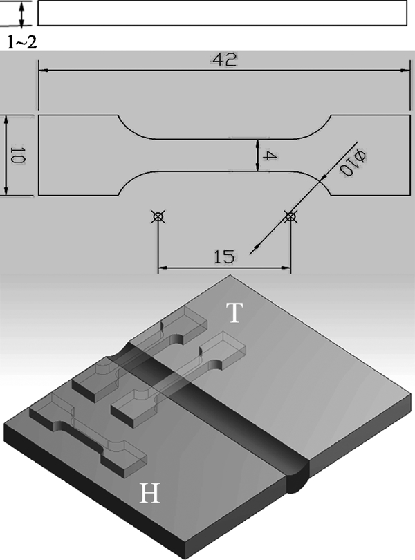
Schematic drawing of two different tensile test specimens used in present investigation
Results and discussion
Macromorphologies of welded seams
The surface appearances and outlines of the FZ of the welded seams achieved without and with different flux coatings at the standard welding condition are shown in Figs. 2 and 3 respectively. Figure 2a shows the result of the welded seam without flux, which exhibited the smoothest surface and showed no visual defects. The surfaces of the welded seams became smooth with the addition of TiO2 coating but rougher (few oxides covered the surfaces) when more TiO2 coating was adopted (see Fig. 2g and h). In addition, the weld width decreased with the addition of TiO2 coating but increased sharply when more TiO2 coating was adopted (see Fig. 3). The weld penetration depths and D/W ratios were measured and are shown in Fig. 4. The CaF2 coating has less influence on the weld penetration depths and D/W ratios of the welded seams. The D/W ratios in the A-TIG welding processes were higher than those in the normal TIG welding process without flux. It was also found that the weld penetration depths and D/W ratios of the weld seams increased gradually with an increase in the amount of TiO2 coating (< 70%). The mix activated flux of 30%CaF2+70%TiO2 led to great improvement in the D/W ratio capability, up to 118% compared with the normal welded seam without flux.
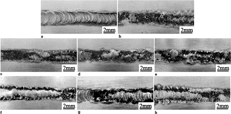
Images of appearances of TIG welded AZ31 magnesium alloy joints without and with different flux coatings
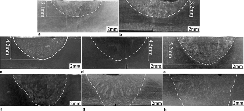
Images of outlines of FZ of TIG welded AZ31 magnesium alloy joints with different flux coatings
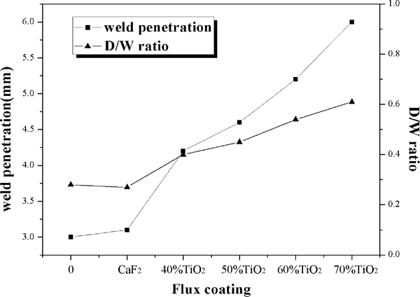
Effects of different flux coatings on weld penetration and D/W ratio of welded seams of TIG welded AZ31 magnesium alloy joints
It was known13– 15 that with the low amount of TiO2 coating, the oxygen almost disaggregated totally when the temperature was above 2000 K. The dissociative oxygen atoms transferred into the molten metal and changed the surface tension temperature coefficient from negative to positive, and then caused the molten metal flow inward to the centre of the welding pool. Hence, a deep and narrow welded seam formed. Whereas, when the amount of TiO2 coating was over 70%, since the temperature at the boundary of the welding pool was below the liquidus of TiO2, part of the TiO2 coatings did not melt in the welding pool. The solid oxide particles floated on the welding pool and then reduced the velocity of the liquid flow in the welding pool. Then, the heat transported by convection reduced while the heat transported by conduction increased. The molten metal flowed to the edge of the welding pool to form a wider welding pool. This result is in accordance with the report of Wang et al. 16
In addition, the CaF2 flux is vapourised as a form of atoms surrounding the circuit of the arc area when the temperature was above 2500 K. For the temperature is rather low at the circuit of the arc area, the vapourising atom of the activating flux catches the electron in this area and forms negative ions, which dissipate to the outward area. The ultimate result is that the arc produces autoconstriction. The arc constriction theory supports that the more the flux vapours enter the arc and the greater extent they are dissociated, the more the arc contracts due to the increase in thermal conductivity of the arc. The constrictive effect increases the temperature in the arc because of the increase in current density.17, 18 In this experiment, the boiling point of CaF2 (2532 K) is far higher than that of the melting point of magnesium alloy (682 K). The temperature of the arc did not change significantly because less vapourising atom of CaF2 was taken into the arc column in the weld process.
Microstructures of welded seams
The typical microstructure of the TIG welded AZ31 magnesium alloy joint without flux coating is shown in Fig. 5a. The microstructure of the TIG welded joint contains of BM, FZ and heat affected zone. The FZ and heat affected zone are mainly composed of the primary and second phases. The EDS analysis results showed that the primary phase contained a large amount of Mg (86·71 at-%) element (see Fig. 5c), while the second phase contained Al (19·58 at-%), Zn (12·03 at-%) and Mg (53·02 at-%) elements (see Fig. 5d). The reason for the existence of the oxygen element is that the surfaces of the specimens were partly oxidised and polluted when it was prepared for SEM test. According to the Mg–Al binary phase diagram and other literature,19, 20 the primary phase is α-Mg (marked with an arrow A in Fig. 5b), and the second phase is β-Mg17(Al, Zn)12 (marked with an arrow B in Fig. 5b). The α-Mg grain in the FZ is finer in comparison to the BM due to the higher cooling rate of the welding pool because of the high thermal conductivity of the AZ31 magnesium alloy. During the TIG welding process, the solidification of the metal in the weld seam is a non-equilibrium process, so the β-Mg17(Al, Zn)12 particles are distributed both at the grain boundaries and in the grains of α-Mg.
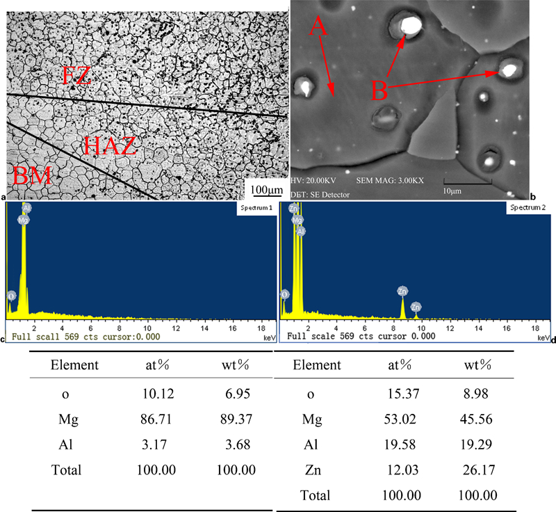
Typical microstructure of TIG welded AZ31 magnesium alloy joint without flux coating and EDS results for primary and second phases
The microstructures of the FZ of the TIG welded AZ31 magnesium alloy joints without and with different flux coatings are shown in Fig. 6. The FZ welded without (Fig. 6a) and with different flux coatings (Fig. 6b–h) all exhibited equiaxed grains in the weld interior. According to the EDS analysis results and the Mg–Al binary phase diagram,20 the microstructure of the FZ is also composed of α-Mg phase and β-Mg17(Al, Zn)12 phases. The FZ welded without flux exhibited a fine crystal grain compared with those with flux coating. It was also found that the α-Mg grains of FZ became fine gradually with the addition of CaF2 coating but coarsened sharply when the amount of TiO2 coating was over 70%.
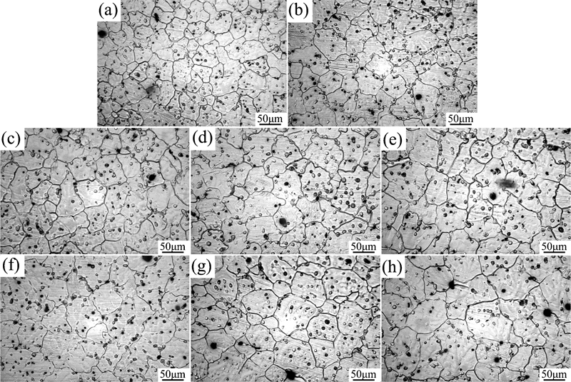
Microstructures of FZ of TIG welded AZ31 magnesium alloy joints without and with different flux coatings
The heat input is low when a low amount of TiO2 flux is coated. Moreover, by increasing the amount of calcium element in the welding pool, the grain refinement of magnesium alloy was improved.21 With an increase in the amount of TiO2 coating, the amount of calcium element in the welding pool decreased. The high heat input and the lower amount of calcium in welding pool caused the coarsening of α-Mg grains of FZ.
The distribution of elements in the FZ of the welded seams of TIG welded AZ31 magnesium alloy joints without and with different flux coatings was measured by EDS equipment. The regions measured included the top, middle and bottom of the FZ. The EDS results of the distribution of titanium element in the FZ of the welded seam of the TIG welded AZ31 magnesium alloy joint with 30%CaF2+70%TiO2 coating are shown in Fig. 7. It can be seen that the element of titanium distributed in the top, middle and bottom of the FZ of the welded seams. In this experiment, the distribution of the titanium element in the weld bead may be explained by the Marangoni flow.
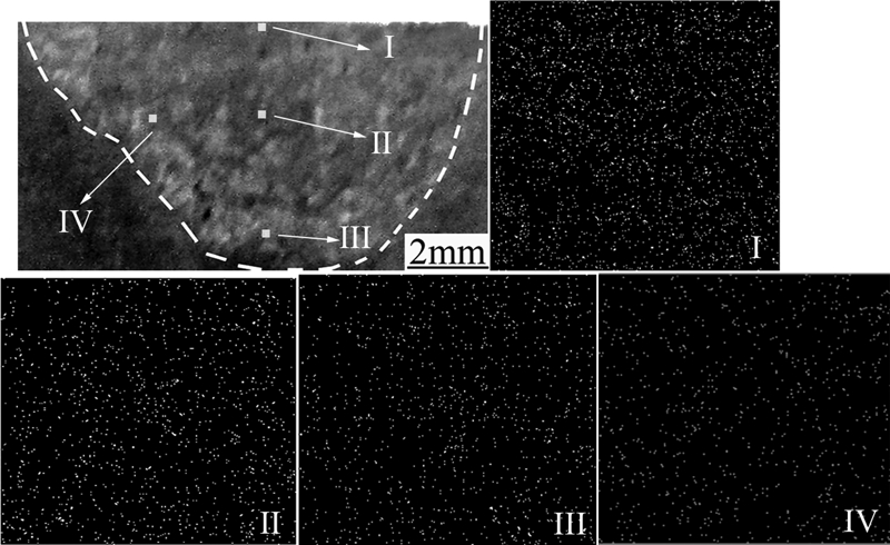
Energy dispersive X-ray spectroscopy results of distribution of titanium element in FZ of welded seam of TIG welded AZ31 magnesium alloy joint with 30%CaF2+70%TiO2 coating
Effects of flux coating on welding defects formed in welded seams
Micropores
Shen et al. 22 studied abnormal macropore formation during double sided gas tungsten arc welding of magnesium AZ91D alloy. They believed that the pores formed in the TIG welded magnesium alloy joints are mainly hydrogen pores. In this study, the hydrogen came from the hydrogen gas by the decomposition of humidity in helium gas under high temperature. Owing to the dissolvability of hydrogen declining sharply with the decrease in the temperature of magnesium (200 mL/100 g at 922·8 K but almost zero at room temperature, as reported by Zeng et al. 23) and the high cooling rate of magnesium alloy, hydrogen gas that had intruded into the magnesium alloy welding pool may have not enough time to escape from it during the rapid solidification of the welding pool, so as to form pores in the welded joints.24, 25
The effects of different flux coatings on the porosities and average diameters of micropores in the FZ of the welded seams of TIG welded AZ31 magnesium alloy joints are shown in Fig. 8. The porosities and average diameters of the micropores declined with the addition of CaF2 coating but increased slightly when more CaF2 coating was adopted. The porosities and average diameters of hydrogen pores reached the minimum value when the mixture of 40%CaF2+60%TiO2 was used in the welding test.
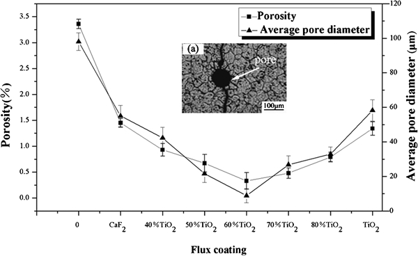
Effects of different flux coatings on porosities and average diameters of micropores in FZ of welded seams of TIG welded AZ31 magnesium alloy joints
The typical micropore in the FZ of the welded seam is shown in Fig. 8a. The cooling rate of the welding pool decreased because the TiO2 and CaF2 coating covered on the welded seam, and this gave hydrogen gas more time to escape from the welding pool. Moreover, fluoride ion that decomposed from the CaF2 flux at high temperature entered into the welding pool as the fluid flow of welding pool. The fluoride ion reacted with hydrogen ion to produce HF gas, which was insoluble in the magnesium alloy welding pool. Therefore, by this chemical reaction process, the hydrogen dissolved into the welding pool was consumed, and then the porosities of hydrogen pores in the welded joint decreased rapidly. In addition, although the hydrogen pores would have enough time to nucleate and grow when the fluxes coat the plates, the increase in the effect of buoyancy on the hydrogen pores from the welding pool led to very few large sized pores being retained in the welded seams. Hence, the porosities and average diameters of the pores increased when a low amount of CaF2 coating was used. Wu et al. 26 study on getting rid of the welding porosity of titanium alloy TC4 by fluxes. The results showed that the CaF2 activating flux used for getting rid of welding porosity is effective because it can reduce the partial pressure of H2 in the electric arc and source of H2 in the welding pool. The mechanism of CaF2 activating fluxes on getting rid of H2 porosity in welded magnesium may be same as this report.
Crackings
The effects of different flux coatings on the total length of solidification cracks in the FZ of the welded seams of TIG welded AZ31 magnesium alloy joints were measured and are shown in Fig. 9. The total length of solidification cracks decreased with the addition of TiO2 coating but increased sharply when more TiO2 coating was adopted. The total length of solidification cracks in the FZ reached the minimum value when the mixture of 30%CaF2+70%TiO2 was used in the welding test. The minimum total length of solidification cracks is ∼119 μm.
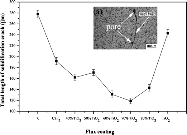
Effects of different flux coatings on total length of solidification cracks in FZ of welded seams of TIG welded AZ31 magnesium alloy joints
The typical solidification cracks formed in the FZ of the welded seam are shown in Fig. 9a. The flux coating reduced the cooling rate of the welding pool. This led to the low melting point β-Mg17(Al, Zn)12 phase solidified almost simultaneously with high melting α-Mg grains. Hence, the formation of solidification cracks in the FZ, which resulted from stress concentration at the grain boundaries of α-Mg grains, was suppressed. Moreover, the micropores also caused stress concentration of the FZ and accelerated the extension of the solidification cracks. Therefore, the decrease in the micropores formed in the FZ reduced the formation of solidification cracks in the welded joints again. However, when the amount of TiO2 coating was too high, a few oxides formed at the top surfaces of the welded seams (as seen in Fig. 2g and h). These oxides involved in the welding pool may come from the flux by fluid flow of the molten welding pool (see Fig. 10). Moreover, more calcium element was involved into the welding pool when the amount of CaF2 coating was too high, and this increased the total length of solidification cracks in the FZ. This result was in agreement with the report of Tang et al., in which the hot crack mechanism of AZ91D alloy with calcium element addition and found that by increasing the amount of added calcium element, the hot crack property of AZ91D alloy decreased.27
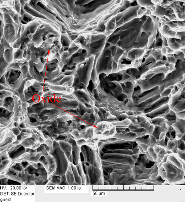
Image (SEM) of oxides in FZ of welded seam of TIG welded AZ31 magnesium alloy joint with TiO2 coating
Figure 11 shows the typical solidification cracks and micropore SEM image of the fracture surface of the specimen with 70%TiO2+30%CaF2 coating. Almost all the cracks are associated with micropores (see Figs. 8a, 9a, and 11). This phenomenon indicated that the cracks in the FZ initiate from micropores and extend along them. This result is in accordance with the report of Sun et al. 28
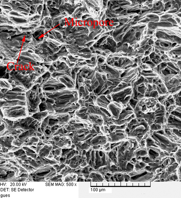
Image (SEM) of typical solidification cracks formed in FZ of welded seam of TIG welded AZ31 magnesium alloy joint with 70%TiO2+30%CaF2 coating
Tensile strength of welded joints
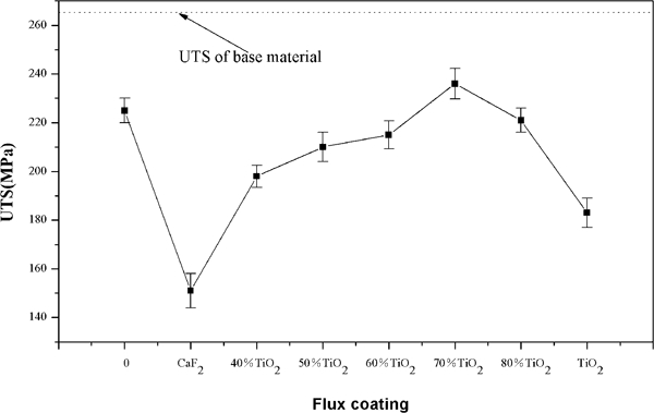
Figure 12 shows the relationship between the different flux coatings and the UTS value of the TIG welded AZ31 magnesium alloy joints. The properties of the BM are considerably higher than that of the weld joints. The welded joint without flux had nearly 86% UTS value of the BM. The UTS value of the welded joints increased with the addition of TiO2 coating but decreased sharply when more TiO2 coating was adopted. The UTS value of the welded joints reached the maximum value (89% of those of the BM) when the amount of the TiO2 coating reached 70%.
Relationship between different flux coatings and UTS value of TIG welded AZ31 magnesium alloy joints
The tensile properties of the welded joints were dominated by welding defects and the grain size of the primary phase. With an increase in the amount of TiO2 coating, the total length of the solidification cracks in the FZ decreased. Therefore, the UTS value of the welded joints increased gradually. More amount of TiO2 coating caused more welding defects and coarsening of the α-Mg grains in the FZ. Therefore, the UTS values of the welded joints decreased sharply when too much amount of TiO2 coatings were added. This result was in agreement with the report of Wang et al., in which AZ31 magnesium alloy coating with TiO2 was welded by TIG welding process.16
Summary
An increase in the amount of TiO2 coating (< 70%) improved the weld penetration and D/W ratio of the TIG welded AZ31 magnesium alloy seams. The mix activated flux of 30%CaF2+70%TiO2 led to great improvement in the D/W ratio capability, up to 118% compared with the normal welded seam without flux. Moreover, the α-Mg grains of FZ became fine gradually with the addition of CaF2 coating but coarsened sharply when the amount of TiO2 coating was over 70%.
The porosities and average diameters of the micropores in the FZ declined with the addition of CaF2 coating but increased slightly when more CaF2 coating was adopted. The total length of solidification cracks in the FZ decreased with the addition of TiO2 coating but increased sharply when more TiO2 coating was adopted.
The UTS value of the welded joints increased with the addition of TiO2 coating because of the decrease in the welding defects in the FZ. However, too much TiO2 coating caused a significant decrease in the UTS value because of the formation of the welding defects and the coarsening of α-Mg grains in the FZ. The UTS value of the welded joints reached the maximum value (89% of those of the BM) when the amount of TiO2 coating reached 70%.
Footnotes
Acknowledgements
This research was financially supported by Fundamental Research Funds for the Central Universities of China (project no. CDJZR11135501), Fundamental Research Funds for the Central Universities (project no.CDJXS10131155) and Supported by Sharing Fund of Chongqing University's Large-Scale Equipment (project no. 2011063023).